Table of Contents
Advertisement
Quick Links
Advertisement
Table of Contents
Troubleshooting

Related Manuals for Advanced Energy Thyro-PX


Summary of Contents for Advanced Energy Thyro-PX
- Page 1 ® Thyro‑PX DC Power Controller User Manual 57010241-00B June 2021 ...
- Page 2 Industries, Inc. All Rights Reserved. DISCLAIMER AND LIMITATION OF LIABILITY The information contained in this manual is subject to change by Advanced Energy Industries, Inc. without prior notice. Advanced Energy Industries, Inc. makes no warranty of any kind whatsoever, either expressed or implied, with respect to the information contained herein.
- Page 3 All other trademarks are the property of their respective owners. CUSTOMER FEEDBACK Advanced Energy’s technical writing staff has carefully developed this manual using research-based document design principles. However, improvement is ongoing, and the writing staff welcomes and appreciates customer feedback. Please send any comments on the content, organization, or format of this user manual to: •...
-
Page 4: Table Of Contents
® ® Advanced Energy Thyro‑PX DC Power Controller Table of Contents Chapter 1. Safety and Product Compliance Guidelines Important Safety Information ................. 1-1 Danger, Warning, and Caution Boxes .............. 1-1 Safety Guidelines .................... 1-2 Rules for Safe Installation and Operation ............ 1-2 Interpreting Product Labels ................ - Page 5 ® ® Advanced Energy Thyro‑PX DC Power Controller Chapter 5. Installation, Setup, and Operation Preparing to Install the Unit ................... 5-1 Spacing Requirements ................... 5-1 Dimensional Drawings .................. 5-1 Installation Requirements ................ 5-2 Unpacking the Unit .................. 5-3 Lifting the Unit .................... 5-3 Installing the Unit .................... 5-4...
- Page 6 Table 3-7. Environmental standard specifications .......... 3-5 Table 3-8. Climatic specifications ................. 3-5 Table 3-9. Type designation .................. 3-6 Table 4-1. Thyro-PX DC status LEDs .............. 4-3 Table 4-2. Relay indications .................. 4-4 Table 4-3. 9-pin digital I/O connector (X51) ............ 4-6 Table 4-4. 9-pin analog I/O connector (X52) ............ 4-7 Table 4-5.
- Page 7 Figure 4-6. Thyro‑Touch display ................ 4-12 Figure 4-7. Connection to local installed server .......... 4-14 Figure 5-1. Thyro-PX DC 3PX 500-1000 HF DC, 1250 HF DC, 1800 HF DC, Thyro-PX DC 3PX 690-1000 HF DC, 1700 HF DC ........ 5-2 Figure 5-2.
-
Page 8: Chapter 1. Safety And Product Compliance Guidelines
Guidelines IMPORTANT SAFETY INFORMATION To ensure safe installation and operation of the Advanced Energy Thyro-PX DC unit, read and understand this manual before attempting to install and operate this unit. At a minimum, read and follow the safety guidelines, instructions, and practices. -
Page 9: Safety Guidelines
® ® Advanced Energy Thyro‑PX DC Power Controller CAUTION: CAUTION indicates a potentially hazardous situation that, if not avoided, could result in minor or moderate injury, and/or property damage. CAUTION is also used for property-damage-only accidents. ATTENTION: ATTENTION indique une situation potentiellement dangereuse qui, si elle n’est pas évitée, pourrait provoquer des blessures mineures ou modérées... - Page 10 ® ® Advanced Energy Thyro‑PX DC Power Controller Complies with applicable European directives. Protective conductor terminal This terminal must be connected first and be of proper type and size for the circuit with the highest voltage and current carrying capacity. Note that...
-
Page 11: Product Compliance
® ® Advanced Energy Thyro‑PX DC Power Controller Short-circuit protected Environmentally Friendly Use Period of 25 years per China RoHS—recycle responsibly at end of life Electrocution hazard Heavy object—can cause muscle strain or back injury Heavy object—do not lift manually... -
Page 12: Safety And Emc Directives And Standards
® ® Advanced Energy Thyro‑PX DC Power Controller For more information, refer to the Certificate or Letter of Conformity (US) or Declaration of Conformity (EU), available on request. • CE Marking – Self-declaration, assessed by AE Corporate Compliance • EMC measurements – Verified by AE Corporate Compliance •... -
Page 13: Interlocks And Limiting Conditions
• EU REACH – European Union Regulation (EC) No. 1907/2006 Registration, Evaluation, Authorization and Restriction of Chemicals Advanced Energy manufactures articles subject to Article 33 of REACH and, upon request, will provide information regarding Substances of Very High Concern (SVHC) currently identified by the European Chemical Agency (ECHA) that are contained in this product, at concentrations greater than 0.1%... -
Page 14: Table 1-1. Interlocks And Limiting Conditions
Les produits Advanced Energy comprennent des dispositifs de verrouillage uniquement si la spécification du produit l’exige. Les dispositifs de verrouillage d’Advanced Energy ne sont pas destinés à satisfaire aux normes de sécurité ni à s’y conformer. Lorsqu’un système comprend un dispositif de verrouillage, vous demeurez responsable de satisfaire aux normes de sécurité... -
Page 15: Chapter 2. Product Overview
• Rectifier systems consisting of up to 3 B6C stacks to create an 18 pulse system (B18C) Due to the use of high quality thyristors, the Thyro-PX DC power controller has a type range of up to 1800 A, and the nominal design loads can reach up to ~1.5 MW at 950 VDC. - Page 16 ® ® Advanced Energy Thyro‑PX DC Power Controller ◦ U, U , I, I , and P control ◦ Operating mode VAR • Flexible connectivity ◦ Standard USB interface ◦ Standard analog and digital I/O ◦ Optional analog and digital I/O extension modules ◦...
-
Page 17: Chapter 3. Specifications
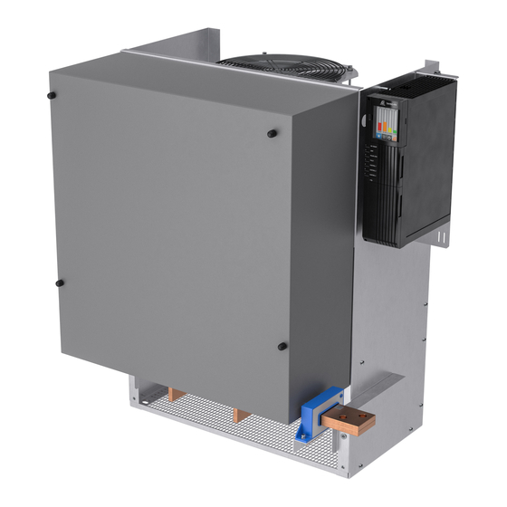
® Thyro‑PX DC Power Controller Chapter Specifications PHYSICAL SPECIFICATIONS Table 3‑1. Physical specifications Description Specification General Physical Specifications Size 683 mm (26.9″) x 787 mm (31.0″) x 521 mm (20.5″) (WxHxD) Dimensional drawing Figure 5‑1 Weight 94 kg to 110 kg (207.2 lb to 242.5 lb) Mounting Mechanical Mounting hardware not included... -
Page 18: Electrical Specifications
® ® Advanced Energy Thyro‑PX DC Power Controller Table 3‑1. Physical specifications (Continued) Description Specification Relay K2 (X22) Included 3-pin, plug-in, screw terminal block, 0.14 mm 1.5 mm (30 AWG - 14 AWG) Relay K3 (X23) Included 3-pin, plug-in, screw terminal block, 0.14 mm 1.5 mm... -
Page 19: Table 3-3. Type Voltage 500 Volts
® ® Advanced Energy Thyro‑PX DC Power Controller Table 3‑2. Electrical specifications (Continued) Description Specification 0(2) V - 10 V Ri = ca. 11.1 kΩ / max. 12 V Analog outputs Signal level 0 V - 10 V, 0 mA - 20 mA or 4 mA - 20 mA. The maximum burden voltage is 10 V. -
Page 20: Cooling Specifications
DC Power Controller COOLING SPECIFICATIONS The Thyro-PX DC power controllers are type HF units and are force cooled. The fan in HF units require a separate power source at 230 V, 50/60 Hz. A 115 V fan is available by special-order for some units. ... -
Page 21: Environmental Specifications
® ® Advanced Energy Thyro‑PX DC Power Controller Table 3‑6. Fan current, air volume, and sound pressure (Continued) Model Current (A) Air Volume Sound Pressure 50 Hz 60 Hz (dbA @ 1 m) Fans for HF units must be running when the unit is operating. Connect the fans according to connecting diagrams. -
Page 22: Type Designation
Maximum absolute humidity when the unit temperature directly decreases from +70°C to +15°C (+158°F to +59°F) TYPE DESIGNATION The type designations of the Thyro-PX DC power controllers are derived from the construction of the unit power section, as shown in the following table. Table 3‑9. Type designation... -
Page 23: Chapter 4. Communication Controls
The unit can be configured using either the Thyro‑Touch display, or via the Thyro- Tool Pro software. The setpoint control characteristic of Thyro-PX DC may be easily adapted for the control output signal of the upstream process controller or automation system. -
Page 24: Status Indicators (Leds)
Simultaneously with the fault signal, you can use the Pulse Lock On/Off (with acknowledgement), Pulse Lock On/Off (without acknowledgement), or Regulator Lock On/Off (without acknowledgement) configuration to require that pulse shutdown occur. The Thyro-PX DC unit LED status indicators are located on the front panel of the unit. ☞ Important This manual describes the default configuration. -
Page 25: Table 4-1. Thyro-Px Dc Status Leds
® ® Advanced Energy Thyro‑PX DC Power Controller Figure 4‑2. Status LEDs Table 4‑1. Thyro-PX DC status LEDs Status ON/READY Green: On, ready for operation Red: Severe hardware fault. (EEPROM fault) Red blinking: Hardware configuration incorrect. Orange blinking: Firmware is being updated. -
Page 26: Relay Indicators
Lock On/Off (without acknowledgement) configuration to require that pulse shutdown occur. The Thyro-PX DC power controller is fitted with three relays. Each of these relays has a change-over contact. AE recommends that users keep the default settings for K1 and K2. Each relay can be reconfigured as normally-open or normally-closed using the Thyro‑Touch display or the Thyro-Tool Pro software. - Page 27 ® ® Advanced Energy Thyro‑PX DC Power Controller • μUSB connector, for configuration using the Thyro-Tool Pro software • 9-pin digital I/O connector, with 6 digital inputs • 9-pin analog I/O connector, with 3 analog inputs, and 3 analog outputs •...
-
Page 28: Table 4-3. 9-Pin Digital I/O Connector (X51)
® ® Advanced Energy Thyro‑PX DC Power Controller X10 RS-232 X6 μUSB X51 Digital I/O X53 Analog/Digital I/O (optional) or Digital I/O (optional) X54 Analog/Digital I/O (optional) or Digital I/O (optional) X52 Analog I/O Figure 4‑3. Front I/O connectors Table 4‑3. 9-pin digital I/O connector (X51) -
Page 29: Table 4-4. 9-Pin Analog I/O Connector (X52)
® ® Advanced Energy Thyro‑PX DC Power Controller Table 4‑4. 9-pin analog I/O connector (X52) Signal Name Function X52.1 + 5 V X52.2 Analog input 1.1 Setpoint power controller 1 X52.3 Analog input 1.2 Setpoint power controller 2 X52.4 Analog input 1.3 Setpoint power controller 3 X52.5... - Page 30 ® ® Advanced Energy Thyro‑PX DC Power Controller Table 4‑6. 16-pin digital I/O connector (X53 or X54) (Continued) Signal Name Function X54.4 Digital input 3.2 User configured X54.5 Digital input 3.3 User configured X54.6 Digital input 3.4 User configured X54.7 Digital input 3.5 User configured X54.8...
-
Page 31: Table 4-7. Relay K1, K2, And K3 Connectors (X21, X22, X23)
® ® Advanced Energy Thyro‑PX DC Power Controller I/O bus 24 V auxiliary power supply input Fault relay K1 Limit relay K2 Optional relay K3 AC auxiliary power supply input Figure 4‑4. Bottom I/O connectors Table 4‑7. Relay K1, K2, and K3 connectors (X21, X22, X23) -
Page 32: Module Slots
The second module slot can be equipped with the dASM module, which is used for the B12C and the B18C configurations. In this case, each Thyro-PX DC power controller must be equipped with a dASM module. 57010241-00B Communication Controls... -
Page 33: Thyro-Touch Display
® ® Advanced Energy Thyro‑PX DC Power Controller Anybus module dASM module Figure 4‑5. Module slots THYRO‑TOUCH DISPLAY The Thyro‑Touch display is an optional accessory for the parameterization and visualization of measured values, such as current, voltage, power, and setpoint. 57010241-00B Communication Controls 4‑11... -
Page 34: Figure 4-6. Thyro-Touch Display
DC Power Controller Figure 4‑6. Thyro‑Touch display In addition to simplifying the handling of the Thyro-PX DC power controller, the Thyro‑Touch display also offers a quick overview of power controller status. Ongoing data can also be displayed as line or bar charts. The integrated data recorder enables a long-term recording of up to six measured values, including status messages. -
Page 35: Thyro-Touch Display Menus
® ® Advanced Energy Thyro‑PX DC Power Controller Warnings are highlighted in yellow, and error messages are highlighted in red on the display. Click on a warning or an error message to see its details in the fault log. The following access levels apply: •... -
Page 36: Using The Software
® ® Advanced Energy Thyro‑PX DC Power Controller Using the Software INSTALLATION To install the Thyro-Tool Pro software, double-click the .exe file provided by AE. ® During installation, a server (Windows service: ThyroWindowsService) and client are installed. The server and client start in parallel when the software is started. -
Page 37: Chapter 5. Installation, Setup, And Operation
• Units may be installed side-by-side with no intervening distance. • Ensure that the unit is not exposed to sources of heat. Dimensional Drawings The following figure shows Thyro-PX DC unit dimensions, front, and side views. 57010241-00B Installation, Setup, and Operation... -
Page 38: Installation Requirements
® Advanced Energy Thyro‑PX DC Power Controller Figure 5‑1. Thyro-PX DC 3PX 500-1000 HF DC, 1250 HF DC, 1800 HF DC, Thyro-PX DC 3PX 690-1000 HF DC, 1700 HF DC Installation Requirements Install this unit according to the following requirements. DANGER: RISK OF DEATH OR BODILY INJURY. -
Page 39: Unpacking The Unit
1. Unpack and inspect the unit carefully, looking for obvious physical damage. 2. If no damage is apparent, proceed with the unit installation and setup. 3. If you do see signs of shipping damage, contact Advanced Energy and the carrier immediately. -
Page 40: Installing The Unit
® ® Advanced Energy Thyro‑PX DC Power Controller TO LIFT THE UNIT • Lift the unit by holding on to the front of the unit while also supporting the rear of the unit. INSTALLING THE UNIT Installing Optional Modules DANGER: RISK OF DEATH OR BODILY INJURY. -
Page 41: Mounting The Unit
® ® Advanced Energy Thyro‑PX DC Power Controller Figure 5‑2. Anybus module removal If an I/O module must be removed from the unit, remove the TORX T8 mounting screws, insert a connector, and pull while moving the module from side to side, as shown in the following figure. -
Page 42: Grounding
® ® Advanced Energy Thyro‑PX DC Power Controller Grounding WARNING: Do not attempt to turn on power until the chassis of the unit is tied to a local earth ground through a copper grounding strap that is sized in accordance with applicable requirements. -
Page 43: Connecting Load And Auxiliary Power
® ® Advanced Energy Thyro‑PX DC Power Controller c. Strip 7 mm (0.28″) of insulation from each conductor. 3. Connect each conductor to the plug-in, screw-terminal block. 4. Plug the block into the power controller. 5. Connect the cable shield to the shield clamp. -
Page 44: Connection Diagrams
® ® Advanced Energy Thyro‑PX DC Power Controller 4. Connect the load to the DC output terminals (DC+, DC-). a. Use the screw size specified in Table 5‑1. b. Tighten to the torque specified in Table 5‑2. 5. Connect a current-limited external power source to the auxiliary power input connector on the bottom of the unit. - Page 45 ® ® Advanced Energy Thyro‑PX DC Power Controller DANGER: RISQUE DE MORT OU DE BLESSURES. Respectez les exigences de votre juridiction locale en matière de verrouillage/étiquetage avant de connecter ou de déconnecter toutes les sources d'alimentation d'entrée et les connexions de sortie.
-
Page 46: Figure 5-4. 3Pxdc 1000A_1250A Power Controller Connections
® ® Advanced Energy Thyro‑PX DC Power Controller Figure 5‑4. 3PXDC 1000A_1250A power controller connections 57010241-00B Installation, Setup, and Operation 5‑10... -
Page 47: Figure 5-5. 3Pxdc 1700A
® ® Advanced Energy Thyro‑PX DC Power Controller Figure 5‑5. 3PXDC 1700A...1800A power controller connections 57010241-00B Installation, Setup, and Operation 5‑11... -
Page 48: Figure 5-6. 3Pxdc Snubber Connections
® ® Advanced Energy Thyro‑PX DC Power Controller Figure 5‑6. 3PXDC snubber connections 57010241-00B Installation, Setup, and Operation 5‑12... -
Page 49: First Time Operation
3. Verify that the light green ON / READY LED is lit. 4. Verify that an increase in setpoint applies power to the load. If the Thyro-PX DC unit is delivering power and the LIMIT LED is not lit, the unit is functioning properly. -
Page 50: Setpoint Control
AE sales representative. SETPOINT CONTROL The setpoint control characteristic of the Thyro-PX DC power controller is easily adapted for the control output signal of the upstream process controller or automation system. All typical control voltage and control current signals can be used. Inverted operation (ending value is smaller than the starting value in voltage or current) is also supported. -
Page 51: Monitoring
® ® Advanced Energy Thyro‑PX DC Power Controller Table 5‑3. Setpoint characteristics (Continued) Input Type Input Characteristics 0 V to 5 V Ri = ca. 6.6 kΩ / max. 12 V 1 V to 5 V 0 V to 10 V Ri = ca. -
Page 52: Fuse Monitoring
B12C AND B18C OPERATION The Thyro-PX DC power controller uses a modular stack system in a B6C configuration. Two units can be connected to create a B12C system, and three units can be connected to create a B18C system. -
Page 53: Connection
® ® Advanced Energy Thyro‑PX DC Power Controller Connection For B12C operation, the AC inputs of the two units are powered by the outputs of a transformer with a Dy5d6 vector group. The master unit must be connected to the secondary star output of the transformer. -
Page 54: Control Wiring
Cable Exposed shield Figure 5‑11. Shield clamp Configuring for B12C and B18C Operation The master and slave Thyro-PX DC power controllers are configured using the Thyro-Tool Pro software. Master Configuration 1. Connect to the master unit via USB. 2. Open the unit in the Port Explorer. - Page 55 ® ® Advanced Energy Thyro‑PX DC Power Controller 3. Select Hardware config. (gen.)→ Basic configuration . 4. Select 1x 3-phase RECT (power units #1, #2, #3). 5. Select Card_S1 - dASM module slot. 6. Select dASM module (RECT master function) from the drop-down list.
- Page 56 ® ® Advanced Energy Thyro‑PX DC Power Controller 9. Select Thyro-PX Power Controller #1→ Rect. 10. Enter the maximum DC output current for each rectifier under Imax_S1, Imax_S2, and for B18C systems Imax_S3. 11. Click the save icon. 12. Disconnect the USB cable from the master unit.
-
Page 57: Maintenance
® ® Advanced Energy Thyro‑PX DC Power Controller 20. Disconnect the USB cable from the slave unit. 21. For B18C systems, configure the second slave unit as instructed in steps 13 through 20. MAINTENANCE Fan Maintenance The fan is subject to wear. Complete the following visual inspection every year: •... -
Page 58: Chapter 6. Troubleshooting And Global Services
® Thyro‑PX DC Power Controller Chapter Troubleshooting and Global Services Before calling AE Global Services, perform recommended checks and troubleshooting procedures. If you are still unable to resolve the issue and resume normal operation after following these checks and procedures, contact AE Global Services. -
Page 59: Ae Global Services
® ® Advanced Energy Thyro‑PX DC Power Controller Table 6‑1. Using LED states for troubleshooting Troubleshooting Action Check Is the green ON/ If no: The auxiliary 230 VAC or 24 VDC supply is faulty. READY LED lit? Is the red ON/ If yes: There is an EEPROM fault. -
Page 60: Primary Contact Information
Click on the service link at the top of the page. Alternate Contact Information If you do not have access to the Advanced Energy website, then use one of the following: • Phone (24 hrs/day, 7 days/week): 800.446.9167 ... - Page 61 ® ® Advanced Energy Thyro‑PX DC Power Controller Index environmental specifications 3‑5 AE customer service contact information 6‑2 authorized returns 6‑3 fan maintenance 5‑21 features 2‑1 B12C B18C configuration 5‑18 operation 5‑16 general description 2‑1 Global Services contact information 6‑2 grounding 5‑6...
- Page 62 ® ® Advanced Energy Thyro‑PX DC Power Controller maintenance physical 3‑1 fan 5‑21 type designation 3‑6 monitoring standards, directives and standards 1‑5 operation 5‑15 status indicators mounting 5‑5 LEDs 4‑2 relays 4‑4 symbols in user manual 1‑1 normal operation 5‑13 on unit 1‑2...
Need help?
Do you have a question about the Thyro-PX and is the answer not in the manual?
Questions and answers