Bennett Marine AutoTrimPro Installation & User Manual
All-in-one trim tab control system, hydraulic trim tab systems
Hide thumbs
Also See for AutoTrimPro:
- Installation & user manual (48 pages) ,
- Installation instructions (2 pages) ,
- Quick start installation manual (2 pages)

Related Manuals for Bennett Marine AutoTrimPro


Summary of Contents for Bennett Marine AutoTrimPro
- Page 1 All-in-one trim tab control system Installation & User's Guide For Hydraulic Trim Tab Systems IMPORTANT SAFETY INSTRUCTIONS: Read and follow all instructions. Keep this manual on your boat.
- Page 2 Maximize Performance While Smoothing Out The Ride: Bennett trim tabs enhance the operating economy of your boat by lifting the stern in proportion to speed, weight distribution, and fuel load changes–and AutoTrim Pro does this automatically for you! Bennett Marine AutoTrim Pro | Need help? Call (954) 427-1400...
-
Page 3: Table Of Contents
Contents .................. Contacting Us System Overview System Overview ....................4 System Components ..................5 Planning and Installation P lanning the Installation ..................6 Installation of System Components ..............7 System Diagrams ....................10 ATP Helm Display Drilling Template ............... 17 System Set-up &... -
Page 4: System Overview
ATP can be combined with the appropriate power switching device and can control many commercially available hydraulic trim tab systems, thus adding a high degree of usability to any system. Bennett Marine AutoTrim Pro | Need help? Call (954) 427-1400... -
Page 5: System Components
Control Unit AutoTrim Pro Kit Part#: AP000A1HA Also included in the box 25' Helm Display extension Optional pump adapter cable (Deutsch to Mate-n-lock) Optional port & starboard sensor adapter cables Bennett Marine AutoTrim Pro | Need help? Call (954) 427-1400... -
Page 6: Planning The Installation
Please call actuators with sensor-equipped upper Bennett Marine at (954) 427-1400 with hinges–available as a conversion kit. Call Bennett Marine at (954) 427- any questions. 1400 to order. Bennett Marine AutoTrim Pro | Need help? Call (954) 427-1400... -
Page 7: Installation Of System Components
LED indicators on the ATP to identify a source for ignition Helm Display to know what the ATP power. Connect the purple wire is doing. from the ATP display to the Bennett Marine AutoTrim Pro | Need help? Call (954) 427-1400... - Page 8 The Control Unit. (Use the provided unit contains an accelerometer, adapter if needed). Connect the gyroscope, and an electronic starboard sensor cable to the Bennett Marine AutoTrim Pro | Need help? Call (954) 427-1400...
- Page 9 44. is an indication that the system has not yet been oriented to the boat (You will complete this step on page 23). Bennett Marine AutoTrim Pro | Need help? Call (954) 427-1400...
-
Page 10: System Diagrams
Bennett Marine Inc. ANY REPRODUCTION additional help with wiring instructions. IN PART OR AS A WHOLE WITHOUT THE NEXT ASSY WRITTEN PERMISSION OF Bennett Marine Inc IS PROHIBITED. (No Sensor Wires) Bennett Marine AutoTrim Pro | Need help? Call (954) 427-1400... - Page 11 10. ATP Helm Display 11. Bridge Helm Display (With Sensor Wires) 12. Bridge Display Extension Cable Please call us at (954) 427-1400 for * Optional additional help with wiring instructions. Bennett Marine AutoTrim Pro | Need help? Call (954) 427-1400...
- Page 12 8. Helm Display Extension Cable Actuators 9. ATP Helm Display 10. Bridge ATP Helm Display Please call us at (No Sensor 11. Y-Harness Cable (954) 427-1400 for Wires) additional help with wiring instructions. Bennett Marine AutoTrim Pro | Need help? Call (954) 427-1400...
- Page 13 11. Port Relay Module (954) 427-1400 for 12. Y-Cable Hydraulic additional help with 13. ATP Helm Display 14. ATP Bridge Helm Display wiring instructions. System (With * Optional Sensor Wires) Bennett Marine AutoTrim Pro | Need help? Call (954) 427-1400...
- Page 14 9. Stbd. Pump Extension Cable (954) 427-1400 for Display 10. Port Pump Extension Cable additional help with 11. Display Extension Cable wiring instructions. System (With 12. Helm Display Sensor Wires) * Optional Bennett Marine AutoTrim Pro | Need help? Call (954) 427-1400...
- Page 15 10. Stbd. Pump Extension Cable Display additional help with 11. Port Pump Extension Cable wiring instructions. System (With 12. Y-Cable 13. Helm Display Sensor Wires) 14. Bridge Helm Display * Optional Bennett Marine AutoTrim Pro | Need help? Call (954) 427-1400...
- Page 16 (With Sensor Wires) 9. Y-harness Cable 10. Stbd. Relay Module 11. Port Relay Module Please call us at (954) 427-1400 for 12. ATP Helm Display additional help with wiring instructions. * Optional Bennett Marine AutoTrim Pro | Need help? Call (954) 427-1400...
-
Page 17: Atp Helm Display Drilling Template
ATP Helm Display Drilling Template 2.13 1.00 Verify template dimensions if printed from the web or copied 2.13 3/16" Must be printed or copied at 100% scale 1" 1" Bennett Marine AutoTrim Pro | Need help? Call (954) 427-1400... - Page 18 Bennett Marine AutoTrim Pro | Need help? Call (954) 427-1400...
-
Page 19: Bennett Marine Autotrim Pro | Need Help? Call (954) 427-1400
Actuator Position Calibration Calibrating Systems with Sensors ..............20 Disabling the LED Alert for Systems Without Sensors ........22 Orientation & Angle Set-up Orientation Set-up ....................23 Angle Set-up ...................... 24 Bennett Marine AutoTrim Pro | Need help? Call (954) 427-1400... -
Page 20: Actuator Position Calibration
22. Press and hold the bright (Sun) and dim (Moon) buttons 4. After a few seconds, the upper two yellow LEDs should begin to flash. simultaneously for about three Bennett Marine AutoTrim Pro | Need help? Call (954) 427-1400... - Page 21 8. Press and hold both BOW UP buttons until both actuators return to the full-up position. The red LEDs on the display should show the actuator position as the actuators retract. Bennett Marine AutoTrim Pro | Need help? Call (954) 427-1400...
-
Page 22: Disabling The Led Alert For Systems Without Sensors
The upper yellow lights should stop flashing and all of yellow LEDs in the corners should be illuminated continuously. Bennett Marine AutoTrim Pro | Need help? Call (954) 427-1400... -
Page 23: Orientation Set-Up
The system will now look for an acceleration due to the boat starting. This must be the next acceleration that the boat experiences. Throttle up to speed without using trim tabs. The Bennett Marine AutoTrim Pro | Need help? Call (954) 427-1400... -
Page 24: Angle Set-Up
Once the buttons are released, the system will flash all four corner LEDs to indicate that a setting has been made. Bennett Marine AutoTrim Pro | Need help? Call (954) 427-1400... - Page 25 "Using Automatic Mode" speed, wait approximately 15 section on page 37. seconds to ensure the boat has settled on plane, then press and hold the Favorite Buttons Bennett Marine AutoTrim Pro | Need help? Call (954) 427-1400...
- Page 26 Bennett Marine AutoTrim Pro | Need help? Call (954) 427-1400...
-
Page 27: Trim Tab Basics
Trim Tab Basics This section is intended to provide a general overview of how trim tabs work. For detailed information on operating your AutoTrim Pro, see page 32. -
Page 28: How Trim Tabs Work
When the port tab is lowered independantly, an upward Port Stbd. force at the port stern of the boat is created. The inverse applies when lowering the stbd. tab independantly. Bennett Marine AutoTrim Pro | Need help? Call (954) 427-1400... - Page 29 An over-trimmed boat will "plow" or "bow-steer". If you over-trim the boat, simply press BOW UP and the bow of the boat will rise. For information about operating ATP auto mode, see page 32. Bennett Marine AutoTrim Pro | Need help? Call (954) 427-1400...
-
Page 30: Special Conditions & Safety
BOW UP on both tabs. This brings up the tabs, decreasing lift in the stern, allowing the bow to rise. If tabs are deployed, the bow may dig. Bennett Marine AutoTrim Pro | Need help? Call (954) 427-1400... - Page 31 • For best maneuverability, trim tabs should be fully retracted in a following sea, or when running in an inlet. For information about operating ATP auto mode, see page 32. Bennett Marine AutoTrim Pro | Need help? Call (954) 427-1400...
-
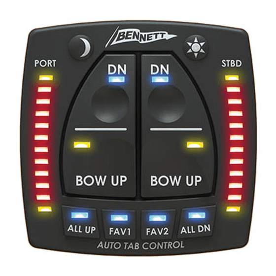
Page 32: Atp Helm Display Quick-Start Guide
(Helm 4. All Up & All Down Semi- station and fly bridge station). The Automatic Controls ATP Helm Display integrates four key features: Bennett Marine AutoTrim Pro | Need help? Call (954) 427-1400... -
Page 33: Indication & Manual Mode Buttons
LEDs on the full-down position the red LEDs will display. illuminate to illustrate the trim tab Bennett Marine AutoTrim Pro | Need help? Call (954) 427-1400... - Page 34 Continue on to the next section for information on automatic and Port tab Stbd.tab semi-automatic features. deploys deploys Bennett Marine AutoTrim Pro | Need help? Call (954) 427-1400...
-
Page 35: Semi-Automatic Controls
In some boats tabs in a full- down condition can make the vessel subject to bow steering at medium to high speeds. Tabs should be brought back up for high speed operation. Bennett Marine AutoTrim Pro | Need help? Call (954) 427-1400... - Page 36 It is normal for the user to retract the trim tabs immediately after getting the boat on plane. Bennett Marine AutoTrim Pro | Need help? Call (954) 427-1400...
-
Page 37: Using Automatic Modes
“FAV 1” Button: Pressing will being set. activate the first stored favorite position. Pressing any manual Bennett Marine AutoTrim Pro | Need help? Call (954) 427-1400... - Page 38 "Understanding Automatic Operation". start automatic operations, the unit must have the FAV position set (see "Setting a Favorite Position" on page 37), and the initial set-up Bennett Marine AutoTrim Pro | Need help? Call (954) 427-1400...
-
Page 39: Understanding Automatic Operation
In normal operation the boat Idle will progress through these basic operation states. The following example shows how a boat may progress through these operating Rest states in normal use. Bennett Marine AutoTrim Pro | Need help? Call (954) 427-1400... - Page 40 The ATP system will automatically The ATP system will move into the Idle Rest mode when the ATP controller move into Accel mode when the ATP Idle Planing Bennett Marine AutoTrim Pro | Need help? Call (954) 427-1400 Rest Acceleration...
- Page 41 Idle Deceleration based on the current speed, loading navigates a desired course. As a boat Bennett Marine AutoTrim Pro | Need help? Call (954) 427-1400 Idle Rest...
- Page 42 Idle mode. As soon as the ATP system compensate for pitch changes. These senses the deceleration and puts the pitch changes are uniform on both tabs down, the system will stop all Bennett Marine AutoTrim Pro | Need help? Call (954) 427-1400...
- Page 43 When in hole rough sea conditions. shot mode, the ATP will leave the Idle Bennett Marine AutoTrim Pro | Need help? Call (954) 427-1400...
-
Page 44: Troubleshooting
ATP Control Unit . An • Solution: Check the fuse at extension cable may be the ATP Helm Display. The used between the ATP Helm fuse should be 1.5A. Bennett Marine AutoTrim Pro | Need help? Call (954) 427-1400... - Page 45 • Solution b: Verify that the actuator LEDs on the ATP Control Unit are illuminated. These are the upper left green LEDs next to the actuator sensor cables on the Bennett Marine AutoTrim Pro | Need help? Call (954) 427-1400...
- Page 46 Trim Tabs not responding • Solution: Verify that the when ATP Helm Display trim tabs function properly buttons are pressed when the manual buttons • Potential Cause 1: There is no Bennett Marine AutoTrim Pro | Need help? Call (954) 427-1400...
- Page 47 Trim tabs owner’s • Potential Cause 2: The ATP manual for full instructions Control Unit has no power applied on HPU installation and to it. troubleshooting. Bennett Marine AutoTrim Pro | Need help? Call (954) 427-1400...
- Page 48 20. the desired attitude using the throttle, engine trim and trim tabs. Press and hold the FAV button. The button must Bennett Marine AutoTrim Pro | Need help? Call (954) 427-1400...
- Page 49 • Solution: Check for a flashing upper yellow light on ATP Helm Display. If the upper yellow LEDs are flashing, refer to the installation troubleshooting section for "Upper yellow LEDs flashing" on page 45. Bennett Marine AutoTrim Pro | Need help? Call (954) 427-1400...
- Page 50 Under the system detects excessive these kinds of conditions, the roll conditions or excessive Bennett Marine AutoTrim Pro | Need help? Call (954) 427-1400...
- Page 51 Control Unit orientation is not adjust the boat under manual correct. operation, it will not be able • Solution: The ATP Control to adjust it under automatic Unit must be oriented to the operation. Bennett Marine AutoTrim Pro | Need help? Call (954) 427-1400...
- Page 52 When the system • Potential Cause 1: Planing Angle does not detect a settling decreased below the idle angle. and a full-tab retraction, it Bennett Marine AutoTrim Pro | Need help? Call (954) 427-1400...
- Page 53 FAV position. • Solution: If the boat is moving fast and the FAV position is set at a relatively low speed, as the boat speed Bennett Marine AutoTrim Pro | Need help? Call (954) 427-1400...
- Page 54 Bennett Marine AutoTrim Pro | Need help? Call (954) 427-1400...
-
Page 55: Warranty
With respect to components Warranty Claim Procedure: To make or products replaced under this warranty, a claim please call Bennett Marine at Bennett Marine reserves the right, in its 954-427-1400 to troubleshoot the issue sole discretion, to provide updated or and start the claim process. - Page 56 Bennett Marine, Inc. 550 Jim Moran Boulevard, Deerfield Beach, FL 33442, USA 954-427-1400 M-F 8am to 5pm (EST) BennettTrimTabs.com Info@BennettTrimTabs.com 954-480-2897 Get Bennett On Board, And Enjoy The Ride ATP62 r081517...
Need help?
Do you have a question about the AutoTrimPro and is the answer not in the manual?
Questions and answers