Bennett Marine AutoTrim Pro Installation & User Manual
All-in-one trim tab control system
Hide thumbs
Also See for AutoTrim Pro:
- Installation & user manual (56 pages) ,
- Installation instructions (2 pages) ,
- Quick start installation manual (2 pages)

Related Manuals for Bennett Marine AutoTrim Pro


Summary of Contents for Bennett Marine AutoTrim Pro
- Page 1 All-in-one trim tab control system Installation & User's Guide For Electric Trim Tab Systems IMPORTANT SAFETY INSTRUCTIONS: Read and follow all instructions. Keep this manual on your boat.
- Page 2 Maximize Performance While Smoothing Out The Ride: Bennett trim tabs enhance the operating economy of your boat by lifting the stern in proportion to speed, weight distribution, and fuel load changes. Bennett Marine | AutoTrim Pro Trim Tab Control System...
-
Page 3: Table Of Contents
Auto Mode Set-up (Favorite Buttons) ............... 16 Trim Tab Basics How Trim Tabs Work ..................20 Special Conditions & Safety ................22 AutoTrim Pro Operation ATP Helm Display Quickstart Guide ..............24 Indication & Manual Mode Buttons ..............25 Semi-Automatic Controls ................27 Using Automatic Modes .................. -
Page 4: System Overview
Proper installation of the system components is critical for safe and optimal operation of the system. The electric ATP control works with all standard Bennett Marine trim electric tab systems and many other electric trim tab systems. The ATP is a complete control system and does not require any other user interface. -
Page 5: System Components
25' Helm Display Extension The AutoTrim Pro (ATP) is an all-in-one trim tab control system consisting of two components, the Helm Display and the Control Unit. Please refer to the system diagram on page 13 for detailed system wiring requirements. -
Page 6: Planning The Installation
Helm Display to know what the ATP is doing. Before installing the ATP Helm Display, check for obstructions on the underside of the helm. See page 8 for detailed installation instructions. Bennett Marine | AutoTrim Pro Trim Tab Control System... - Page 7 The location of the ATP control unit within the boat is not critical, but the orientation of the ATP control unit to the boat is very important. Bennett Marine | AutoTrim Pro Trim Tab Control System...
-
Page 8: Installation Of System Components
If a second helm station is utilized in Helm Display through the 1" hole this system, repeat steps 1-5 only for the upper station ATP Helm Display. 5. Secure the ATP Helm Display Bennett Marine | AutoTrim Pro Trim Tab Control System... - Page 9 3. Mount the Control Unit using the two #8 x ½" screws provided. 4. Connect the orange and black power wires to a power source Bennett Marine | AutoTrim Pro Trim Tab Control System...
- Page 10 ATP Helm Display. The Starboard actuator should extend. If the Starboard actuator does not extend, or the PORT actuator extends instead of the Starboard actuator, refer to the troubleshooting section. Bennett Marine | AutoTrim Pro Trim Tab Control System...
-
Page 11: Atp Helm Display Drilling Templates
ATP Helm Display Drilling Template 2.13 1.00 Verify template dimensions if printed from the web or copied 2.13 3/16" Must be printed or copied at 100% scale 1" 1" Bennett Marine | AutoTrim Pro Trim Tab Control System... - Page 12 Bennett Marine | AutoTrim Pro Trim Tab Control System...
-
Page 13: System Wiring Diagram
6. Display Extension Cable *Optional This diagram also works with Single Helm Display, Lenco Marine actuators Single Actuators IN P Please call us at (954) 427-1400 for additional help with wiring instructions Bennett Marine | AutoTrim Pro Trim Tab Control System... -
Page 14: System Set-Up
The system will flash all four corner taking measurements. The system LEDs to indicate that a setting has will use the average of all the been made. measurements that were taken while Bennett Marine | AutoTrim Pro Trim Tab Control System... - Page 15 This is not the target position, but it’s fastest safe speed to set the rather the limits of the operation planing angle. When the boat has range of the trim tabs. settled into a steady pitch position Bennett Marine | AutoTrim Pro Trim Tab Control System...
-
Page 16: Auto Mode Set-Up (Favorite Buttons)
FAV1 or FAV2 buttons are being held, the system will constantly take pitch and roll measurements. When the FAV1 or FAV2 button is released, the system Favorite 1 Favorite 2 Bennett Marine | AutoTrim Pro Trim Tab Control System... - Page 17 System Set Up: Auto Mode (Favorites) Set-up Bennett Marine | AutoTrim Pro Trim Tab Control System...
-
Page 19: Trim Tab Basics
Trim Tab Basics... -
Page 20: How Trim Tabs Work
Trim Tab Basics This section is intended to provide a general overview of how trim tabs work. For detailed information on operating your AutoTrim Pro, see page 24. Bennett trim tabs most often attach to the bottom edge of the transom (although other mounting variations are available). - Page 21 An over-trimmed boat will plow or bow-steer. If you over-trim the boat, simply press BOW UP and the bow of the boat will rise. For information about operating ATP auto mode, see page 24. Bennett Marine | AutoTrim Pro Trim Tab Control System...
-
Page 22: Special Conditions & Safety
Trim Tab Basics continued This section is intended to provide a general overview of how trim tabs work. For detailed information on operating your AutoTrim Pro, see page 24. Special Conditions & Safety Precautions Correcting for a List Bennett Trim Tabs may be operated individually so that you can correct for listing. - Page 23 This section is intended to provide a general overview of how trim tabs work. For detailed information on operating your AutoTrim Pro, see page 24. Windy Chop To raise the windward side of the boat press BOW UP on that side. If this is not sufficient, press BOW DOWN on the leeward side of the boat.
-
Page 24: Autotrim Pro Operation
(Helm 4. All Up & All Down Semi- station and fly bridge station). The Automatic Controls ATP Helm Display integrates four basic control features: Bennett Marine | AutoTrim Pro Trim Tab Control System... -
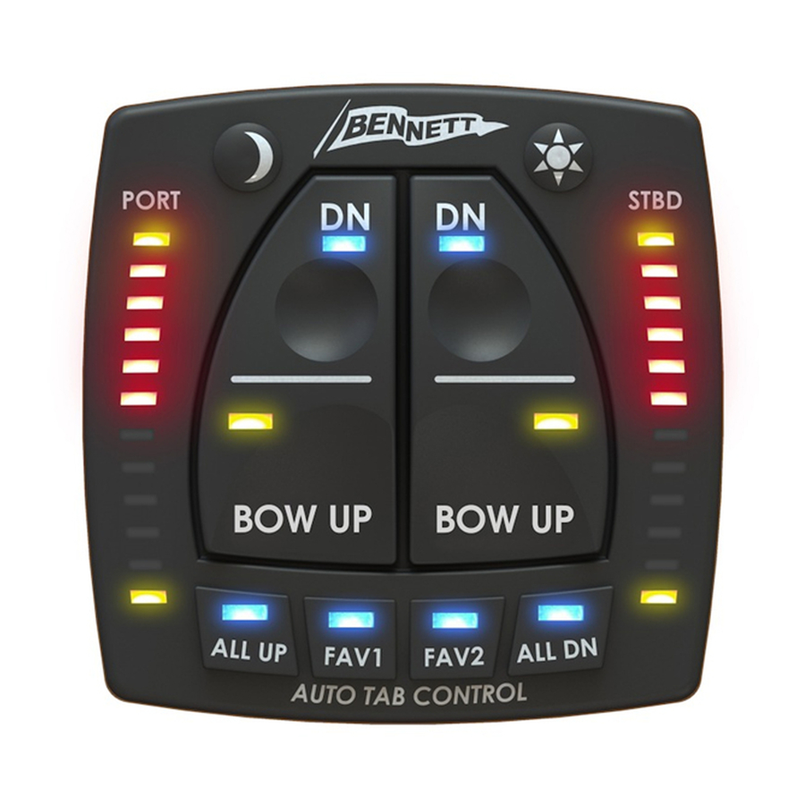
Page 25: Indication & Manual Mode Buttons
LEDs on the full-down position the red LEDs will display. illuminate to illustrate the trim tab Bennett Marine | AutoTrim Pro Trim Tab Control System... - Page 26 Continue on to the next section for information on automatic and Port tab Stbd.tab semi-automatic features. deploys deploys Bennett Marine | AutoTrim Pro Trim Tab Control System...
-
Page 27: Semi-Automatic Controls
In some boats tabs in a full down condition can make the vessel subject to bow steering at medium to high speeds. Tabs should be brought back up for high speed operation. Bennett Marine | AutoTrim Pro Trim Tab Control System... - Page 28 It is normal for the user to retract the trim tabs immediately after getting the Sets Favorite Sets Favorite Position 1 Position 2 boat on plane. Bennett Marine | AutoTrim Pro Trim Tab Control System...
-
Page 29: Using Automatic Modes
“FAV 1” Button: Will activate the first stored favorite position. set. Bennett Marine | AutoTrim Pro Trim Tab Control System... - Page 30 For a detailed explanation of how auto mode works, see the following start automatic operations, the unit section "Understanding Automatic must have the FAV position set (see Operation". "Setting a Favorite Position" on page Bennett Marine | AutoTrim Pro Trim Tab Control System...
-
Page 31: Understanding Automatic Operation
6. Deceleration In normal operation the boat Idle will progress through these basic operation states. The following example shows how a boat may progress through these operating Rest states in normal use. Bennett Marine | AutoTrim Pro Trim Tab Control System... - Page 32 Accel mode when the ATP Rest mode when the ATP controller Idle Controller senses an acceleration senses that the boat is at or below the Planing Bennett Marine | AutoTrim Pro Trim Tab Control System Rest Acceleration Turning...
- Page 33 Idle based on the current speed, loading Deceleration navigates a desired course. As a boat and water conditions, then the ATP turns, the changing water flow under Rest Bennett Marine | AutoTrim Pro Trim Tab Control System Idle...
- Page 34 If the turn is more than just automatic adjustments, as trim tabs Bennett Marine | AutoTrim Pro Trim Tab Control System...
- Page 35 When in hole rough sea conditions. shot mode, the ATP will leave the tabs down until the boat’s attitude Idle Bennett Marine | AutoTrim Pro Trim Tab Control System...
-
Page 36: Troubleshooting
• Solution: Check fuse at the ATP Control Unit . An ATP Helm Display. Fuse should be 1.5A extension cable may be used Bennett Marine | AutoTrim Pro Trim Tab Control System... - Page 37 ATP Helm Display and the trim tabs function properly Control Unit. when the manual buttons are pressed. Follow the • Solution a: Verify that the Orientation procedure on ATP display communications page 14. Bennett Marine | AutoTrim Pro Trim Tab Control System...
- Page 38 Power LED in the lower center of the ATP Control Unit is illuminated. If it is not illuminated, check the power supplied to the orange and black wires of the ATP Control Unit. Bennett Marine | AutoTrim Pro Trim Tab Control System...
- Page 39 No Response from ALL Not completed DN Button • Solution: Follow the Set-Up • Potential Cause: Tabs are already procedure in page 14. in full-down position. • Solution: System is working as designed Bennett Marine | AutoTrim Pro Trim Tab Control System...
- Page 40 Display and the ATP Control position that was set Unit. If there is a temporary • Potential Cause 1: Position power outage the system has been accidentally reset by will shut down and restart. Bennett Marine | AutoTrim Pro Trim Tab Control System...
- Page 41 (Starboard) tab to go down. rest Verify that when in manual • Potential Cause: Idle Angle is set mode that pressing the upper right manual control button too low. Bennett Marine | AutoTrim Pro Trim Tab Control System...
- Page 42 FAV position. determine that the boat needs • Solution: If the boat is to put the tabs down. If the boat is accelerated very moving fast and the FAV Bennett Marine | AutoTrim Pro Trim Tab Control System...
- Page 43 Once the tabs are full up, the tabs no longer have any effect on the bow Bennett Marine | AutoTrim Pro Trim Tab Control System...
-
Page 45: Warranty
With respect to components Warranty Claim Procedure: To make or products replaced under this warranty, a claim please call Bennett Marine at Bennett Marine reserves the right, in its 954-427-1400 to troubleshoot the issue sole discretion, to provide updated or and start the claim process. - Page 48 Bennett Marine, Inc. 550 Jim Moran Boulevard, Deerfield Beach, FL 33442, USA 954-427-1400 M-F 8am to 5pm (EST) BennettTrimTabs.com Info@BennettTrimTabs.com 954-480-2897 Get Bennett On Board, And Enjoy The Ride ATP 63 r010617...
Need help?
Do you have a question about the AutoTrim Pro and is the answer not in the manual?
Questions and answers