
Related Manuals for Bennett Marine BOLT129


Summary of Contents for Bennett Marine BOLT129
- Page 1 Installation & User's Guide IMPORTANT SAFETY INSTRUCTIONS: Read and save all instructions. This manual may periodically be subject to change, for the most current version visit BennettTrimTabs.com/BoltManual.
- Page 2 Congrats! Making an investment in Bennett Marine's durable and dependable spectrum of products will keep you enjoying the boating experience all the more. We've been a trusted name in the industry for over half a century with exceptional products built to perform, and to last.
-
Page 3: Table Of Contents
Contents Contacting Us ......................2 Parts List & Specifications ..............BOLT Trim Tab System Parts List ..................System Specifications Trim Tab Overview & Operation ..................How Trim Tabs Work ................Special Conditions & Safety Installation Instructions ..............Actuator & Trim Tab Installation ................ -
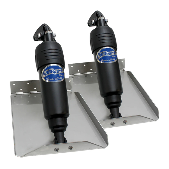
Page 4: Bolt Trim Tab System Parts List
Actuator Upper Hinge Screws (#14 x 1-1/2") EH1071 Trim Tab Screws (#10 x 1-1/4") aries H1175 Actuator Lower Hinge Screws (1/4-20 x 3/4" Phillips) Helm controls sold separately. See page 17 for more information . Bennett Marine | Bolt Electric Trim Tab System... -
Page 5: System Specifications
20 amp in-line fuse. (3 types of controls, see page 18). Used only for dual station and/or dual actuator Communications Junction Box applications. Helm controls sold separately. See page 17 for more information . Bennett Marine | Bolt Electric Trim Tab System... -
Page 6: How Trim Tabs Work
Port Stbd. When the port tab is lowered individually, an upward Port force at the port stern of the boat is created. The Stbd. inverse applies when lowering the stbd. tab individually. Bennett Marine | Bolt Electric Trim Tab System... - Page 7 Be careful not to over-trim your boat. An over- trimmed boat will plow or bow-steer. If you over-trim the boat, simply press BOW UP and the bow of the boat will rise. Bennett Marine | Bolt Electric Trim Tab System...
-
Page 8: Special Conditions & Safety
To raise the windward side of the boat press BOW UP on that side. If this is not sufficient, press BOW DOWN on the leeward side of the boat. This allows the windward side of the boat to rise and minimizes spray. Do not overtrim when attempting this. Bennett Marine | Bolt Electric Trim Tab System... - Page 9 • While operating trim tabs, use caution. Improper use of trim tabs may cause accidents and/or injury. • For best maneuverability, trim tabs should be fully retracted in a following sea, or when running in an inlet. Bennett Marine | Bolt Electric Trim Tab System...
-
Page 10: Actuator & Trim Tab Installation
• 2.5" (6.35 cm) or & 3/16" drill bits • Straight edge 1" (2.54 cm) hole saw • Tape measure • Marking pencil (See pg. 28 & 29) • 4' (1.22 m) level Bennett Marine | Bolt Electric Trim Tab System... - Page 11 Verify that there are no mounting restrictions inside or outside the transom. • Drill the mounting plate holes, using a 5/32" drill bit. Bennett Marine | Bolt Electric Trim Tab System...
- Page 12 • Repeat the previous steps for the opposite side of the boat. If your Bolt set came with adjustable upper hinge actuators (BEA3000), please skip to page 14 “Mounting Adjustable Upper Hinge Actuators (BEA3000) to the Transom.” Bennett Marine | Bolt Electric Trim Tab System...
- Page 13 » For help with connectors visit BennettTrimTabs.com/ ConnectorHelp. • Mount the upper hinge of the new actuator to the transom using the supplied #14 x1- 1/2" screws with a #3 Phillips head screw driver. Bennett Marine | Bolt Electric Trim Tab System...
- Page 14 • Ensure that the cable sealing the adjustable upper hinge using grommet is moved down the cable the supplied 5/16-18 bolt and lock to its seat on the upper hinge. nut to set the cable length. Bennett Marine | Bolt Electric Trim Tab System...
- Page 15 • Screw the adjustable upper hinge to the transom using (2) of the supplied #14 x 1-1/2" screws in the lower 2 mounting positions. Bennett Marine | Bolt Electric Trim Tab System...
- Page 16 » Ensure the proper wire color is on the correct side of the connector. The black actuator wire should match the black Bennett Marine | Bolt Electric Trim Tab System...
-
Page 17: Helm Control Installation
LEDs for day or night. This control deployed (down) requires a relay module. (See Pg. 21) Refer to wiring diagrams and Raises Raises Dims Brightens Port Bow Starboard Bow installation templates beginning LEDs LEDs on page 24. Bennett Marine | Bolt Electric Trim Tab System... - Page 18 (PN# BAW20XX) to the starboard connector on the BRC Rocker Control. • Connect the orange wire from the rocker switch to (+) 12V (20A) power and black wire to ground. Turn the battery on. • For troubleshooting, see page 33 Bennett Marine | Bolt Electric Trim Tab System...
- Page 19 Auto Tab Retraction (ATR) when the ignition is switched to the OFF position. If ATR is not desired, this connection may be omitted. • Relay Module is required (see page 21). • Turn the battery on. • For troubleshooting, see page 34 Bennett Marine | Bolt Electric Trim Tab System...
- Page 20 Auto Tab Retraction (ATR) when the ignition is switched to the OFF position. If ATR is not desired, this connection may be omitted. • Relay module is required (see page 21) • Turn the battery on . For troubleshooting, see page 35 Bennett Marine | Bolt Electric Trim Tab System...
-
Page 21: Relay Module Installation
• Plug the 3 ft. extension cable on the display to the 3 ft. extension cable on the BCN relay module (If cable length is not long enough, an extension is available as part number BHW40XX). Bennett Marine | Bolt Electric Trim Tab System... -
Page 22: Extension Cable Installation
ON position and and the starboard extension cable check the system for functionality. to the starboard actuator. For dual station or dual actuator applications, refer to the wiring diagrams beginning on page 24. Bennett Marine | Bolt Electric Trim Tab System... -
Page 23: Control Testing/Diagnostics
• Press the starboard "Bow Up" button. The port red LEDs should turn off as the starboard actuator retracts. • If the system is not functioning as described above, refer to the troubleshooting section beginning on page 33. Bennett Marine | Bolt Electric Trim Tab System... -
Page 24: System Wiring Diagrams & Installation Templates
Wiring Diagrams continued Bennett Marine | Bolt Electric Trim Tab System... - Page 25 Wiring Diagrams continued Please call us at (954) 427-1400 for help with additional wiring instructions Bennett Marine | Bolt Electric Trim Tab System...
- Page 26 Wiring Diagrams continued Bennett Marine | Bolt Electric Trim Tab System...
- Page 27 Wiring Diagrams continued Please call us at (954) 427-1400 for help with additional wiring instructions Bennett Marine | Bolt Electric Trim Tab System...
-
Page 32: General Maintenance & Safety Precautions
» Apply two coats of • Refer to safety trim tab anti-fouling paint. The precautions on page 9 actuator, including the piston, may be painted. Bennett Marine | Bolt Electric Trim Tab System... -
Page 33: Troubleshooting
Re-insert orange wire use a volt-Ohm the actuator wires into the meter to check this connector in the reverse order. Re-insert the orange wedge- Bennett Marine | Bolt Electric Trim Tab System... - Page 34 » Verify that the power source at the relay module and at the to the orange wire on the display display is turned ON. If this Bennett Marine | Bolt Electric Trim Tab System...
- Page 35 Remove » Verify that the green the orange wedge-lock from communications LED is the connector. Remove the flashing. If the green LED is contacts from the connector Bennett Marine | Bolt Electric Trim Tab System...
- Page 36 Push the » Check that the green wires up into the connector Bennett Marine | Bolt Electric Trim Tab System...
- Page 37 » The actuators are reversed. - STOP and call Bennett for further Unplug the actuators at the assistance at (954) 427-1400, Monday extension cable and switch through Friday, 8:00 a.m. to 5:00 the connections between Bennett Marine | Bolt Electric Trim Tab System...
-
Page 38: Limited Warranty
Warranty Claim Procedure: To make a claim please call Bennett Marine at 954-427-1400 to trouble-shoot the issue and start the claim process. You will be asked to complete a form that can be found online at BennettTrimTabs.com/Warranty and return the part for warranty... -
Page 39: Warranty Period
Return Procedure For Customers Outside Us: For international returns, please refer to our worldwide distributor map on our website BennettTrimTabs.com/find-a-dealer to contact your local Bennett Marine distributor for warranty and returns procedures in your respective country. PRODUCT PERIOD... - Page 40 Bennett Marine, Inc. 550 Jim Moran Boulevard, Deerfield Beach, FL 33442, USA 954-427-1400 M-F 8am to 5pm (EST) BennettTrimTabs.com Info@BennettTrimTabs.com 954-480-2897 Download your owners instruction manual at BennettTrimTabs.com/BoltManual Get Bennett On Board, And Enjoy The Ride BQE120 r071416...
Need help?
Do you have a question about the BOLT129 and is the answer not in the manual?
Questions and answers