Table of Contents
Advertisement
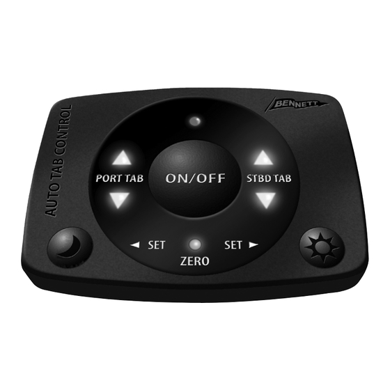
AUTO TAB CONTROL (ATC)
OWNER'S MANUAL &
INSTALLATION INSTRUCTIONS
IMPORTANT:
This manual contains critical
information directly affecting the safe and efficient
operation of your boat. Please read thoroughly before
operating the Auto Tab Control system.
SAVE AND KEEP WITH
BOAT OWNER'S INFORMATION
This pdf was downloaded from
MarineSupplyDock.com
Advertisement
Table of Contents

Related Manuals for Bennett Marine AUTO TAB CONTROL


Summary of Contents for Bennett Marine AUTO TAB CONTROL
- Page 1 INSTALLATION INSTRUCTIONS IMPORTANT: This manual contains critical information directly affecting the safe and efficient operation of your boat. Please read thoroughly before operating the Auto Tab Control system. SAVE AND KEEP WITH BOAT OWNER’S INFORMATION This pdf was downloaded from MarineSupplyDock.com...
-
Page 2: Section 1 A Basic Product Understanding
Important: The ATC Control Unit must be mounted correctly or the ATC system will not function as it should. C: Relay Module — The Relay Module Links the Hydraulic Power Unit to the Auto Tab Control system. This pdf was downloaded from MarineSupplyDock.com... -
Page 3: Section 2 Before Installing The Auto Tab Control, You Must Check The Trim Tab System Installation
SECTION 2 BEFORE INSTALLING THE AUTO TAB CONTROL, YOU MUST CHECK THE TRIM TAB SYSTEM INSTALLATION The ATC system interfaces with the boat’s trim tab system, and automatically operates the trim tab Hydraulic Power Unit (HPU). Therefore before you install and operate the ATC system it is critical you confirm that the HPU wiring and hydraulic tubing is connected EXACTLY as described in items 1 and 2 below. -
Page 4: Section 3 Using The Auto Tab Control For The First Time
For Boat Leveler Insta-Trim Systems The Auto Tab Control installation instructions are based on Bennett Trim Tab wire colors. If you are installing the Auto Tab Control on a Boat Leveler system, the wire color conversion is as follows: •... - Page 5 Turning the ATC on. Once you’ve set the Zero Point you can now press the ON/OFF button for 2-3 seconds to turn your ATC on. It will now take control of your trim tabs. ATC Memory. Once the Zero Point is set, the ATC will retain this attitude in memory permanently, or until it is reset.
-
Page 6: Section 4 Activating And Deactivating The Auto Tab Control
SECTION 4 ACTIVATING AND DEACTIVATING THE AUTO TAB CONTROL The ATC system is activated by pressing the ON/OFF button for 2-3 seconds. When the button is released, the red ON/OFF LED lights up indicating the unit is operating. Once activated, the ATC continuously analyzes and calculates the attitude of your boat and directs messages to operate the trim tabs. -
Page 7: Section 6 Troubleshooting The System
1. Activating the ATC system causes the boat to list (lean). • Trim tab tubing or wiring may be crossed. See the “Before Installing the Auto Tab Control” section of this manual. • ATC system Zero Point may be incorrectly set. - Page 8 AUTO TAB CONTROL (ATC) INSTALLATION INSTRUCTIONS IMPORTANT: Plan how you will lay out the system. Consider the wire runs from the Keypad to the Control Unit. Make sure battery power is disconnected! For Non-Electronic Bennett Trim Tab Control Systems (Rocker Switch Control, Single Lever Control and Racing Type Control)
- Page 9 Step 2: Mounting the ATC Keypad • Cut out the template from the last page of this manual. • Tape the template to the dash where you intend to mount the Keypad. (Make sure it is within 6 feet of the Control Unit.) Check behind panel for wires or obstruction.
- Page 10 Zero Point is set. If you turn on the ATC at this point, the blue Zero Set LED light will flash. Refer to section 3, “Using the Auto Tab Control for the first time.” This pdf was downloaded from...
- Page 11 Zero Point is set. If you turn on the ATC at this point, the blue Zero Set LED light will flash. Refer to section 3, “Using your Auto Tab Control for the first time.” This pdf was downloaded from...
- Page 12 System Schematic and Parts List for Non-Electronic Trim Tab Controls Description Part # 1 ATC Keypad AC3250 Optional Upper Station 2 ATC 6' Keypad Cable AC32506 Description Part # 3 ATC Control Unit AC3400 ATC Keypad AC3250 4 ATC Power Pigtail AC3121 10 ATC 22' Keypad Cable AC325022 5 Pigtail for Wire Harness...
- Page 13 System Schematic and Parts List for Bennett Electronic Indicator Control System Description Part # Optional Upper Station 1 ATC Keypad AC3250 2 ATC 6' Keypad Cable AC32506 Description Part # 3 ATC Control Unit AC3400 ATC Keypad AC3250 4 ATC Power Pigtail AC3121 ATC 22' Keypad Cable AC325022 5 Pigtail for Wire Harness...
- Page 14 If you have any questions regarding the installation of the Bennett Auto Tab Control, please contact us at Bennett Marine, Inc 550 Jim Moran Blvd. Deerfield Beach, FL 33442 Phone: 954-427-1400 Email: info@BennettTrimTabs.com Web: www.BennettTrimTabs.com This pdf was downloaded from...
- Page 15 This pdf was downloaded from MarineSupplyDock.com...
- Page 16 ATC20 P-ATC-X This pdf was downloaded from MarineSupplyDock.com...
Need help?
Do you have a question about the AUTO TAB CONTROL and is the answer not in the manual?
Questions and answers