Table of Contents
Advertisement
Quick Links
WWW.SEAGULLMODELS.COM
A S S E M B L Y M A N U A L
" Graphics and specifications may change without notice " .
MS: 208
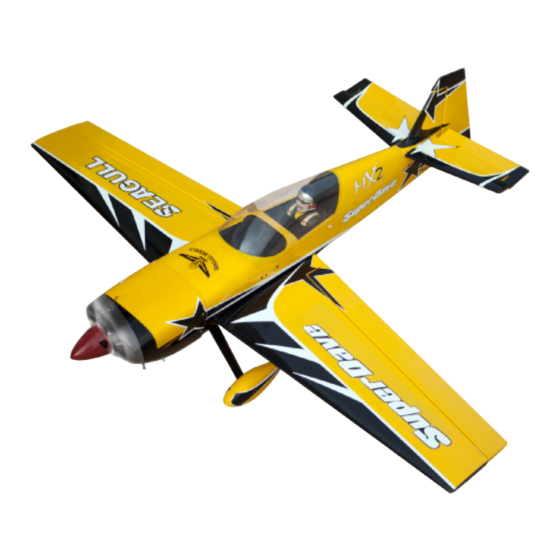
Specifications:
Wingspan---------------59.1 in (150 cm).
Wing area----------------632.4 sq.in (40.8 sq.dm).
Weight-------------------7.1 - 7.9 lbs (3.2 - 3.6 kg).
Length-------------------50.3 in (127.7cm).
ARF
Engine-------------------0.55cu.in--------2 stroke
----------------------------0.82cu.in--------4 stroke
----------------------------10cc gasoline.
Radio--------------------4 channel with 5 servos.
Electric power conversion.
www.seagullmodels.com
1
Advertisement
Table of Contents

Related Manuals for Seagull Models SuperDave MX2


Summary of Contents for Seagull Models SuperDave MX2
- Page 1 WWW.SEAGULLMODELS.COM A S S E M B L Y M A N U A L “ Graphics and specifications may change without notice “ . MS: 208 Specifications: Wingspan---------------59.1 in (150 cm). Wing area----------------632.4 sq.in (40.8 sq.dm). Weight-------------------7.1 - 7.9 lbs (3.2 - 3.6 kg). Length-------------------50.3 in (127.7cm).
-
Page 2: Kit Contents
Instruction Manual. INTRODUCTION. Thank you for choosing the SUPER DAVE MX2 ARTF by SEAGULL MODELS COMPANY LTD,. The SUPER DAVE was designed with the intermediate/advanced sport flyer in mind. It is a semi scale airplane which is easy to fly and quick to assemble. The airframe is onventionally built using balsa, plywood to make it stronger than the average ARTF, yet the design allows the aeroplane to be kept light. -
Page 3: Hinging The Ailerons
WWW.SEAGULLMODELS.COM KIT CONTENTS. HINGING THE AILERONS Note : The control surfaces, including the SEA20801 Fuselage ailerons, elevators, and rudder, are SEA20802 Wing set prehinged with hinges installed, but SEA20803 Tail set the hinges are not glued in place. It is SEA20804 Cowling imperative that you properly adhere... -
Page 4: Hinging The Elevator
SUPER DAVE MX2 Instruction Manual. Hinge. 5) Turn the wing panel over and deflect the 4) Deflect the aileron and completely aileron in the opposite direction from the saturate each hinge with thin C/A glue. The opposite side. Apply thin C/A glue to each ailerons front surface should lightly contact the hinge, making sure that the C/A penetrates wing during this procedure. -
Page 5: Hinging The Rudder
WWW.SEAGULLMODELS.COM Epoxy HINGING THE RUDDER. Glue the rudder hinges in place using the INSTALL ELEVATOR CONTROL HORN. same techniques used to hinge the ailerons. Install the elevator control horn using the same method as same as the aileron control horns. Elevator Control Horn. -
Page 6: Installing The Stopper Assembly
SUPER DAVE MX2 Instruction Manual. Thread locker glue Rudder Control Horn. Epoxy INSTALLING THE STOPPER ASSEMBLY. 1) Using a modeling knife, carefully cut off the rear portion of one of the 3 nylon tubes Rudder Control Horn. leaving 1/2” protruding from the rear of the stopper. -
Page 7: Fuel Tank Installation
WWW.SEAGULLMODELS.COM You should mark which tube is the vent and which is the fuel pickup when you attach fuel tubing to the tubes in the stopper. Once the tank is installed inside the fuselage, it may be difficult to determine which is which. 7) Slide the fuel tank into the fuselage. - Page 8 SUPER DAVE MX2 Instruction Manual. INSTALLING THE MAIN LANDING GEAR TO FUSELAGE. M4x20mm WHEEL AND WHEEL PANTS. 1) The blind nuts for securing the landing 1) Locate the items neccessary to install. gear are already mounted inside the fuselage. 2) Follow diagram below for wheel pant in- stallation: 2) Using the hardware provided, mount the main landing gear to the fuselage.
-
Page 9: Installing The Fuselage Servos
WWW.SEAGULLMODELS.COM Wheel collar. Axle. Washer. Wheel. Wheel collar. Wheel. Repeat steps as above to attach remaining wheel pants to the landing gear. Washer. Axle. INSTALLING THE FUSELAGE SERVOS. nut.-- Because the size of servos differ, you Wheel Pant. may need to adjust the size of the precut opening in the mount. -
Page 10: Installing The Switch
SUPER DAVE MX2 Instruction Manual. THROTTLE SERVO ARM INSTALLA- TION. Install adjustable servo connector in the ser- vo arm as same as picture below: Loctite secure. Adjustable Servo Switch. connector. Servo arm 1 PCS. Rudder Throttle Trim and cut. Elevator INSTALLING THE SWITCH. - Page 11 WWW.SEAGULLMODELS.COM 6) Connect the Z-bend in the 600mm throt- 2) Use a pin drill and 4mm drill bit to drill a tle pushrod to the outer hole of the carbure- small indentation in the mount for the en- tor arm. gine mounting screw.
- Page 12 SUPER DAVE MX2 Instruction Manual. 9) Move the throttle stick to the closed posi- Cut. tion and move the carburetor to closed. Use a 2.5mm hex wrench to tighten the screw that secures the throttle pushrod wire. Make sure to use threadlock on the screw so it does not vibrate loose.
- Page 13 WWW.SEAGULLMODELS.COM Needle valve. - Model size: .46 -.52 size models - Propeller: 12x6 ~ 13x6 - ESC: 60A - Lipo Batteries: 4 cell 4200mA 3x10mm 2) Attach the electric motor box to the fire- wall suitable with the cross lines drawn on the electric motor box and firewall.
- Page 14 SUPER DAVE MX2 Instruction Manual. 3x15 mm 4) Locate the plywood battery tray to the fuselage. Tighten the screws using machine screws M3x15mm to secure the tray in posi- tion. Epoxy 125mm Balsa 3) Attach the motor to the front of the elec- tric motor box using four 4mm blind nut, four M3x15mm hex head bolts to secure the Epoxy...
-
Page 15: Installing The Aileron - Flap Servos
WWW.SEAGULLMODELS.COM The propeller should not touch any part of the spinner cone. If it does, use a sharp Speed Control. modeling knife and carefully trim away the spinner cone where the propeller comes in contact with it. Tie wraps. INSTALLING THE AILERON - FLAP SERVOS. - Page 16 SUPER DAVE MX2 Instruction Manual. 1) Using a small weight (Weighted fuel pick- up works well) and string, feed the string through the wing as indicated. 2) Place the servo between the mounting blocks and space it from the hatch. Use a pencil to mark the mounting hole locations 6) Secure the servo to the aileron hatch using on the blocks.
- Page 17 WWW.SEAGULLMODELS.COM 2x10 mm AILERON PUSHROD HORN INSTALLATION. Please see below pictures. Use a felt tip pen to mark the wire where it crosses the hole. Use a pair of pliers to put a shrp 90-degree bend in the wire at the mark.
-
Page 18: Installing The Horizontal Stabilizer
SUPER DAVE MX2 Instruction Manual. 2) Using a modeling knife, carefully remove the covering at mounting slot of horizontal stabilizer ( both side of fuselage). Bend at the mark M2 lock nut. Metal clevis. Snap keeper. Cut. Servo arm. 3) Slide the stabilizer into place in the precut Snap keeper. -
Page 19: Installing Vertical Stabilizer
WWW.SEAGULLMODELS.COM 5) Remove the stabilizer. Using the lines you just drew as a guide, carefully remove the covering from between them using a mod- eling knife. Remove covering. INSTALLING VERTICAL STABILIZER. When cutting through the covering to remove it, cut with only enough pressure to only cut through the covering itself. - Page 20 SUPER DAVE MX2 Instruction Manual. 3) Slide the vertical stabilizer back in place. ELEVATOR PUSHROD HORN Using a triangle, check to ensure that the ver- INSTALLATION. tical stabilizer is aligned 90º to the horizontal 1) Install the elevator control horn using stabilizer.
- Page 21 WWW.SEAGULLMODELS.COM RUDDER PUSHROD HORN INSTALLATION. M2 clevis. M2 lock nut. M2 clevis. M2 lock nut.
-
Page 22: Mounting The Tail Wheel
SUPER DAVE MX2 Instruction Manual. 3 x 20mm. Wing tube. M2 Clevis Fuel Tubing Hex Nut MOUNTING THE TAIL WHEEL. Locate items necessary to install tail wheel. 3x25 mm. Aluminum tail landing gear. -
Page 23: Apply The Decals
WWW.SEAGULLMODELS.COM - Apply a bead of canopy glue around the in- INSTALLATION PILOT AND CANOPY. side edge of the canopy. Position the canopy onto the hatch. Use tape to hold the canopy 1) Locate items necessary to install pilot and secure until the glue fully cures. - Page 24 SUPER DAVE MX2 Instruction Manual. Battery. Receiver Wing Bolt ATTACHMENT WING-FUSELAGE. Attach the aluminium tube into fuselage. 4x20 mm Wing Tube. BALANCING. 1) It is critical that your airplane be bal- Insert two wing panels as pictures below. anced correctly. Improper balance will cause your plane to lose control and crash.
-
Page 25: Control Throws
WWW.SEAGULLMODELS.COM Accurately mark the balance point on the top of the wing on both sides of the fuse- lage. The balance point is located 110 mm 110mm back from the leading edge of the wing at the wing root. This is the balance point at which your model should balance for your first flights. - Page 26 SUPER DAVE MX2 Instruction Manual.
-
Page 27: Flight Preparation
WWW.SEAGULLMODELS.COM FLIGHT PREPARATION. PREFLIGHT CHECK. 1) Completely charge your transmitter and Check the operation and direction of the receiver batteries before your first day of flying. elevator, rudder, ailerons and throttle. 2) Check every bolt and every glue joint in A) Plug in your radio system per the the SUPER DAVE MX2 to ensure that every- manufacturer’s instructions and turn eve-...
Need help?
Do you have a question about the SuperDave MX2 and is the answer not in the manual?
Questions and answers