Table of Contents
Advertisement
Quick Links
SIZE: 91-120
MS:128
ASSEMBLY MANUAL
"Graphics and specifications may change without notice".
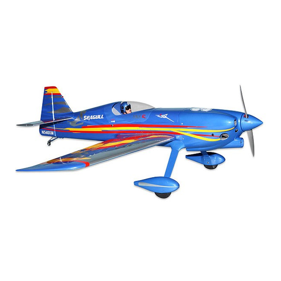
Specifications:
Wing span ----------------------------65.4in (166cm).
Wing area -----------------767.3sq.in (49.5sq dm).
Weight ----------------------9.3-10.6lbs (4.2-4.8kg).
Length ------------------------------55.8in (141.8cm).
Engine ------------------ 0.91-1.2cu.in ----2-stroke.
1.00-1.25cu.in ----4-stroke.
Electric conversion: optional
Radio -----------6 channels with 5 digital servos.
Advertisement
Table of Contents

Related Manuals for Seagull Models MXS-R


Summary of Contents for Seagull Models MXS-R
- Page 1 SIZE: 91-120 MS:128 ASSEMBLY MANUAL “Graphics and specifications may change without notice”. Specifications: Wing span ----------------------------65.4in (166cm). Wing area -----------------767.3sq.in (49.5sq dm). Weight ----------------------9.3-10.6lbs (4.2-4.8kg). Length ------------------------------55.8in (141.8cm). Engine ------------------ 0.91-1.2cu.in ----2-stroke. 1.00-1.25cu.in ----4-stroke. Electric conversion: optional Radio -----------6 channels with 5 digital servos.
-
Page 2: Kit Contents
. Flying the MXS-R is simply a joy. This instruction manual is designed to help you build a great flying aeroplane. Please read this manual thoroughly before starting assembly of your MXS-R . Use the parts listing below to identify all parts. -
Page 3: Hinging The Ailerons
www.seagullmodels.com KIT CONTENTS. HINGING THE AILERONS . Note: The control surfaces, including the Fuselage ailerons, elevators, and rudder, are Canopy prehinged with hinges installed, but Left wing panel the hinges are not glued in place. It Right wing panel is imperative that you properly Tail set adhere the hinges in place per the Aluminum wing tube... -
Page 4: Instruction Manual
Instruction Manual. MXS-R Hinge. 5) Turn the wing panel over and deflect the 4)Deflect the aileron and completely aileron in the opposite direction from the saturate each hinge with thin C/A glue. The opposite side. Apply thin C/A glue to each... -
Page 5: Hinging The Elevator
www.seagullmodels.com HINGING THE ELEVATOR. Glue the elevator hinges in place using the same techniques used to hinge the ailerons. 6mm. HINGING THE RUDDER. Glue the rudder hinges in place using the same techniques used to hinge the ailerons. 6mm. Place epoxy into hole. This will harden the threads and prevent the crews from pulling loose. - Page 6 Instruction Manual. MXS-R Aileron control horn. INSTALL ELEVATOR CONTROL HORN. Install the elevator control horn using the same method as same as the aileron control horns. 3x35mm. 2 sets. Elevator control horn. INSTALL RUDDER CONTROL HORN. Repeat steps to install the rudder control horn as same as steps done for ailerons.
-
Page 7: Engine Mount Installation
www.seagullmodels.com Rudder control horn. 6mm. ENGINE MOUNT INSTALLATION. 1) Locate the items necessary to install the engine mount included with your model. . 6mm. M4x30mm. 2) Use four M4x30mm head bolts and four 4mm washers to attach the engine mount rails to the firewall. - Page 8 Instruction Manual. MXS-R Thread locker glue. Epoxy. + 1.20 : 2 STROKE + 4 STROKE. Epoxy. Balsa. Balsa. Blind nut. Epoxy.
-
Page 9: Installing The Battery
www.seagullmodels.com Thread locker glue. Epoxy. INSTALLING THE BATTERY. Battery. Epoxy. Balsa. Battery. Balsa. Tie Wrap. Epoxy. -
Page 10: Installing The Stopper Assembly
Instruction Manual. MXS-R 3) Carefully bend the second nylon tube INSTALLING THE STOPPER ASSEMBLY. up at a 45º angle. This tube is the vent tube. 1) Using a modeling knife, carefully cut 4) Test fit the stopper assembly into the off the rear portion of one of the 3 nylon tubes tank. - Page 11 www.seagullmodels.com WHEEL AND WHEEL PANTS Balsa wood included. INSTALLATION. 1) Locate the items neccessary to install the wheel and wheel pants as shown. Fuel tank. C/A glue. Vent tube. 2) Follow diagram below for wheel pant installation: Use a drill and 8mm drill bit to drill a hole in the Fuel pick up tube.
- Page 12 Instruction Manual. MXS-R 6) Slide the threaded end of the axle through the hole in the bottom of the landing gear leg. Use a washer and locknut to tighten the axle to the landing gear. Make sure to use threadlock on the nut so it won’t vibrate loose in flight as shown.
- Page 13 www.seagullmodels.com INSTALLING THE MAIN LANDING GEAR TO FUSELAGE. 8) The blind nuts for securing the landing gear are already mounted inside the fuselage. 9) Using the hardware provided, mount the main landing gear to the fuselage. 10) Place the fuselage inverted on the workbench in a suitable stand.
- Page 14 Instruction Manual. MXS-R C/A glue. M4x20mm. C/A glue.
- Page 15 www.seagullmodels.com INSTALLING THE FUSELAGE SERVOS. Rudder servo . Elevator servo . Because the size of servos differ, you may need to adjust the size of the precut open- ing in the mount. The notch in the sides of the mount allow the servo lead to pass through. 1) Install the rubber grommets and brass collets onto the throttle servo.
- Page 16 Instruction Manual. MXS-R 4) On the fire wall has the location for the throttle pusshrod tube (pre-drill). 5) Slide the pushrod tube in the firewall and guide it through the fuel tank mount. Use medium C/A to glue the tube to the firewall and the fuel tank mount.
- Page 17 www.seagullmodels.com Because of the size of the cowl, it may be nec- 9) Move the throttle stick to the closed position and move the carburetor to closed. Use a 2.5mm essary to use a needle valve extension for the hex wrench to tighten the screw that secures high speed needle valve.
-
Page 18: Mounting The Engine
Instruction Manual. MXS-R MOUNTING THE ENGINE. + ENGINE 1.20 : 2 STROKE. 1) Position the engine with the drive washer (150mm) forward of the firewall as shown. 4) On the fire wall has the location for the throttle pusshrod tube (pre-drill). - Page 19 www.seagullmodels.com 8) Reinstall the servo horn by sliding the connector over the pushrod wire. Center the Trim and cut. throttle stick and trim and install the servo horn perpendicular to the servo center line. 9) Move the throttle stick to the closed position and move the carburetor to closed.
- Page 20 Instruction Manual. MXS-R 3) Use a drill to drill the four holes in the engine mount rails. 4.5mm. 3) Install the muffler and muffler extension onto the engine and make the cutout in the cowl for muffler clearance. Connect the fuel...
- Page 21 www.seagullmodels.com Pushrod wire. Machine screw M4x30mm. 8) Reinstall the servo horn by sliding the connector over the pushrod wire. Center the throttle stick and trim and install the servo horn perpendicular to the servo center line. Trim and cut. 9) Move the throttle stick to the closed position and move the carburetor to closed.
- Page 22 Instruction Manual. MXS-R 2) While keeping the back edge of the ELECTRIC POWER CONVERSION. cowl flush with the marks, align the front of the cowl with the crankshaft of the engine. The 1) Locate the items neccessary to install the...
- Page 23 www.seagullmodels.com Epoxy. 3mm. 3) Attach the motor to the front of the electric motor box using four 4mm blind nut, four M4x15mm hex head bolts to secure the motor. Please see picture shown. M4x15mm. 5.2mm. Epoxy. 5.2mm. 215mm. Epoxy. Blind nut. Balsa stick.
-
Page 24: Installing The Spinner
Instruction Manual. MXS-R INSTALLING THE SPINNER. Balsa stick. Install the spinner backplate, propeller and spinner cone. Blind nut. 4) Locate the plywood battery tray to the fuselage. Tighten the screws using machine screws M3x15mm to secure the tray in position. - Page 25 www.seagullmodels.com Small weight. String. 2) Place the servo between the mounting blocks and space it from the hatch. Use a pencil 6) Secure the servo to the aileron hatch using to mark the mounting hole locations on the Phillips screwdriver and the screws provided blocks.
- Page 26 Instruction Manual. MXS-R AILERON PUSHROD HORN INSTALLATION 85mm. M3 clevis. M3 lock nut. 115mm. Wing. M2 lock nut. Aileron.
-
Page 27: Installing The Horizontal Stabilizer
www.seagullmodels.com Wing Aileron Wing Aileron Repeat the procedure for the other aileron servo. 4) Install the stabilizer onto the fuselage. INSTALLING THE HORIZONTAL STABILIZER. Align the centerline drawn on the top and the rear of the stabilizer with the centre of the fu- 1) Using a ruler and a pen, locate the selage. - Page 28 Instruction Manual. MXS-R When cutting through the covering to remove it, cut with only enough pressure to only cut through the covering itself. Cut- ting into the balsa structure may weaken 8) Using a modeling knife, carefully re- move the covering that overlaps the stabilizer mounting platform sides in the fuselage.
-
Page 29: Installing The Vertical Stabilizer
www.seagullmodels.com 10) After the epoxy has fully cured, re- While holding the vertical stabilizer move the masking tape or T-pins used to hold firmly in place, use a pen and draw a line on the stabilizer in place. Carefully inspect the each side of the vertical stabilizer where it glue joints. - Page 30 Instruction Manual. MXS-R C/A glue. Epoxy. Masking tape. 4) When you are sure that everything is ELEVATOR PUSHROD HORN aligned correctly, mix up a generous amount of INSTALLATION. Flash 30 Minute Epoxy. Apply a thin layer to the mounting slot and to bottom of the vertical sta- 1) Install the elevator control horn using bilizer mounting area.
- Page 31 www.seagullmodels.com 3) Thread one clevis and M2 lock nut on to each elevator control rod. Thread the horns Pen. on until they are flush with the ends of the con- trol rods. 4) Elevator and rudder pushrods assembly as pictures below. 495mm.
- Page 32 Instruction Manual. MXS-R Elevator pushrod. Control horn. M2 lock nut. Plastic part. Metal clevis. Rudder pushrod. Elevator pushrod. Pen. C/A glue. Rudder pushrod. Elevator pushrod. Cut. 8mm. C/A glue. Wire keeper. Elevator control horn. Rudder control horn.
-
Page 33: Mounting The Tail Wheel
www.seagullmodels.com 1) Elevator and rudder pushrods assembly follow pictures below. 2) Install servos arm to servos. Notice the position of the servo arms on the servos. See picture below. Rudder. M3x30mm. M3x25mm. Elevator. M3x25 mm. Throttle. Rudder. MOUNTING THE TAIL WHEEL. Locate items necessary to install tail wheel. - Page 34 Instruction Manual. MXS-R 2) A scale pilot is included with this ARF. The M3x30 mm. Seagull Pilot included fitting well to the cockpit. (or you can order others scale pilot figures made by Seagull factory. They are available at Seagull distributors.)
-
Page 35: Apply The Decals
www.seagullmodels.com 4) Position the canopy onto the fuselage. Trace around the canopy and onto the fuselage using a felt-tipped pen. APPLY THE DECALS. - Apply a bead of canopy glue around the inside 1) If all the decals are precut and ready to edge of the canopy. -
Page 36: Attachment Wing - Fuselage
Instruction Manual. MXS-R ATTACHMENT WING-FUSELAGE. BALANCING. Attach the aluminium tube into fuselage. 1) It is critical that your airplane be balanced correctly. Improper balance will cause your plane to lose control and crash. THE CENTER OF GRAVITY IS LOCATED 100 MM BACK FROM THE LEADING EDGE OF THE WING AT THE WING ROOT. -
Page 37: Control Throws
www.seagullmodels.com CONTROL THROWS. Ailerons: 15mm up 20mm down. Elevator: 15mm up. 20mm down. 100mm. Rudder: 25mm left. 40mm right. FLIGHT PREPARATION. D) Check the throttle. Moving the Check the operation and direction of the throttle stick forward should open the carbu- elevator, rudder, ailerons and throttle. -
Page 38: Preflight Check
6) Check to ensure the control surfaces 2) Check every bolt and every glue joint are moving the proper amount for both low in the MXS-R to ensure that and high rate settings. everything is tight and well bonded. 7) Check the receiver antenna. It should...
Need help?
Do you have a question about the MXS-R and is the answer not in the manual?
Questions and answers