Table of Contents
Advertisement
Quick Links
www.seagullmodels.com
MS: X68
ASSEMBLY MANUAL
"Graphics and specifications may change without notice".
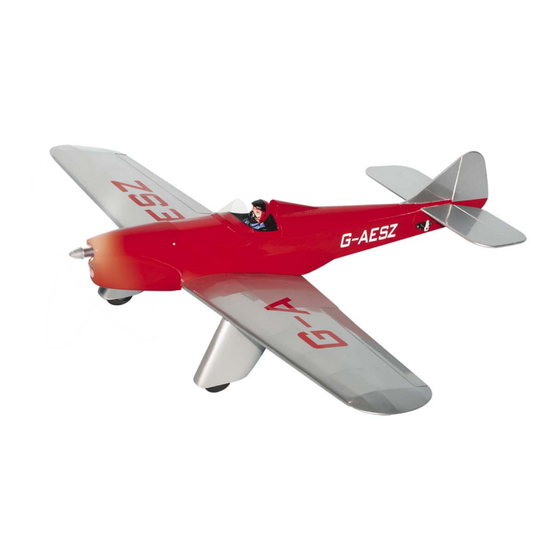
Specifications:
Wing span ---------------------------35.4in (90cm).
Wing area --------------235.6sq.in (15.2sq dm).
Weight ---------------- 1.4-1.9lbs (0.63-0.85kg).
Length -----------------------------29.6in (75.2cm).
Speed control (ESC)------------15A-30A amp.
Motor -------------------------------------- 450-480.
Radio ----------- 4 channels with 4 mini servos.
Battery 3-cell 1800mAh to 2100mAh Li-Po.
10 x 5E Electric Prop.
1
Advertisement
Table of Contents

Related Manuals for Seagull Models Mini Sparrowhawk EP


Summary of Contents for Seagull Models Mini Sparrowhawk EP
- Page 1 www.seagullmodels.com MS: X68 ASSEMBLY MANUAL “Graphics and specifications may change without notice”. Specifications: Wing span ---------------------------35.4in (90cm). Wing area --------------235.6sq.in (15.2sq dm). Weight ---------------- 1.4-1.9lbs (0.63-0.85kg). Length -----------------------------29.6in (75.2cm). Speed control (ESC)------------15A-30A amp. Motor -------------------------------------- 450-480. Radio ----------- 4 channels with 4 mini servos. Battery 3-cell 1800mAh to 2100mAh Li-Po.
-
Page 2: Kit Contents
SPARROWHAWK EP is simply a joy. This instruction manual is designed to help you build a great flying aeroplane. Please read this manual thoroughly before starting assembly of your MINI SPARROWHAWK EP . Use the parts listing below to identify all parts. -
Page 3: Hinging The Ailerons
www.seagullmodels.com HINGING THE AILERONS . KIT CONTENTS. Fuselage Note: The control surfaces, including the Canopy ailerons, elevators, and rudder, are Left wing panel prehinged with hinges installed, but Right wing panel the hinges are not glued in place. It Tail set is imperative that you properly Carbon fiber wing tube adhere the hinges in place per the... -
Page 4: Hinging The Elevators
MINI SPARROWHAWK EP Instruction Manual. Hinge. 5) Turn the wing panel over and deflect the aileron in the opposite direction from the opposite side. Apply thin C/A glue to each hinge, making sure that the C/A penetrates into both the aileron and wing panel. -
Page 5: Hinging The Rudder
www.seagullmodels.com INSTALL THE AILERONS CONTROL HORN. Apply epoxy glue. Glue the elevator hinges in place using the same techniques used to hinge the ailerons. Epoxy. HINGING THE RUDDER. Glue the rudder hinges in place using the Aileron control horn . same techniques used to hinge the ailerons. -
Page 6: Installing The Fuselage Servos
MINI SPARROWHAWK EP Instruction Manual. Epoxy. Epoxy. Rudder control horn. INSTALLING THE FUSELAGE SERVOS. Because the size of servos differ, you may need to adjust the size of the precut open- ing in the mount. The notch in the sides of the mount allow the servo lead to pass through. - Page 7 www.seagullmodels.com Rudder servo. INSTALLING THE AILERON. 4) Apply 2-3 drops of thin C/A to each of the mounting holes. Allow the C/A to cure without using accelerator. Servos. Small weight. Thread. Because the size of servos differ, you 5) Use dental floss to secure the connection may need to adjust the size of the precut open- so they cannot become unplugged.
-
Page 8: Electric Power Installation
MINI SPARROWHAWK EP Instruction Manual. 8) A string has been provided in the wing to pull the aileron lead through to the wing root. Remove the string from the wing at the servo location and use the tape to attach it to the servo extension lead. - Page 9 www.seagullmodels.com 3) Attach the motor to the front of the electric 4) Locate the plywood battery tray to the motor box using four 3mm blind nut, four fuselage. M3x15mm hex head bolts to secure the motor. Please see picture shown. Battery.
-
Page 10: Installing The Spinner
MINI SPARROWHAWK EP Instruction Manual. Trim and cut. INSTALLING THE SPINNER. Install the spinner backplate, propeller and Because of the size of the cowl, it may be nec- spinner cone. essary to use a needle valve extension for the high speed needle valve. Make this out of suf- ficient length 1mm wire and install it into the end of the needle valve. - Page 11 www.seagullmodels.com Trim and cut. When cutting through the covering to re- move it, cut with only enough pressure to only cut through the covering itself. Cutting into the balsa structure may weaken it. 6) Using a modeling knife, carefully re- 2) Using a modeling knife, carefully remove move the covering that overlaps the stabilizer the covering at mounting slot of horizontal sta-...
- Page 12 MINI SPARROWHAWK EP Instruction Manual. INSTALLING VERITICAL FIN. Cut. When cutting through the covering to re- 1) Using a modeling knife, remove the move it, cut with only enough pressure to only cut through the covering itself. Cutting covering from over the precut hinge slot cut into the lower rear portion of the fuselage.
- Page 13 www.seagullmodels.com ELEVATOR - RUDDER PUSHROD HORN AILERON PUSHROD HORN INSTALLATION INSTALLATION. 1) Install the elevator control horn using the same method as with the aileron control horns. 2) Position the elevator control horn on the both side of elevator. Wing. Rudder control horn.
- Page 14 MINI SPARROWHAWK EP Instruction Manual. INSTALLING WIRE LANDING GEAR. 1) Locate the items necessary to attach the main landing gear. 1mm. 2) Remove the covering from over two main landing gear mounting slots located in the bottom of the wing.
- Page 15 www.seagullmodels.com Epoxy. 3.5mm. Installation wheel cover as shown: Repeat the procedure for other landing gear. Screw. M2x12mm.
-
Page 16: Apply The Decals
MINI SPARROWHAWK EP Instruction Manual. INSTALLATION PILOT FIGURE. APPLY THE DECALS. 1) If all the decals are precut and ready to stick. Please be certain the model is clean and free from oily fingerprints and dust. Position decal on the model where desired, using the photos on the box and aid in their location. -
Page 17: Control Throws
www.seagullmodels.com Lift the model. If the tail drops when you lift, the model is “tail heavy” and you must add weight* to the nose. If the nose drops, it is “nose heavy” and you must add weight* to the tail to balance. *If possible, first attempt to balance the model by changing the position of the receiver battery Wing bolt. -
Page 18: Flight Preparation
A) Plug in your radio system per the manufacturer's instructions and turn every- 2) Check every bolt and every glue joint in the MINI SPARROWHAWK EP to ensure thing on. that B) Check the elevator first. Pull back on everything is tight and well bonded.
Need help?
Do you have a question about the Mini Sparrowhawk EP and is the answer not in the manual?
Questions and answers