Table of Contents
Advertisement
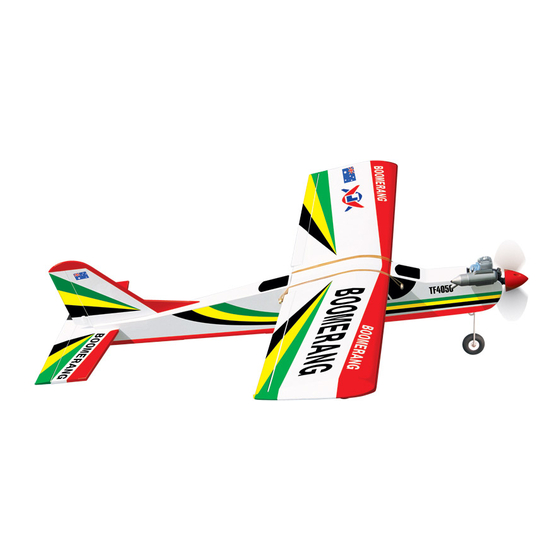
SPORTS TRAINER - ENGINE SIZE.40 - .46 - 2STROKE
Hand-made Almost Ready to Fly R/C Model Aircraft
Specifications
Wingspan _____________________________ 155cm.
Wing area _________________________ 3950 sq cm .
Approximate flying weight _______________ 2.6-2.8kg.
Recommended engine size 0.40-0.46 cu. ins 2-stroke.
Recommended R/C ___________ 4 channel minimum.
Flying skill level ___________________ Sports Trainer.
Kit features.
•
Ready-made—minimal assembly & finishing required.
•
Ready-covered—including decals, trim & covering.
•
Factory-installed pushrod.
•
Factory-pinned & glued control surface hinges for ultimate safety.
•
Comprehensive hardware pack including wheels, tank, spats,undercarriage& spinner.
•
Photo-illustrated step-by-step Assembly Manual.
ASSEMBLY MANUAL
Engine.
4 Channel or greater Radio Control system.
Glues.
Tools.
Starting Equipment.
Made in Vietnam.
Advertisement
Table of Contents

Related Manuals for Seagull Models Boomerang 40


Summary of Contents for Seagull Models Boomerang 40
- Page 1 SPORTS TRAINER - ENGINE SIZE.40 - .46 - 2STROKE Hand-made Almost Ready to Fly R/C Model Aircraft ASSEMBLY MANUAL Specifications Additional items required. Wingspan _____________________________ 155cm. Wing area _________________________ 3950 sq cm . Engine. Approximate flying weight _______________ 2.6-2.8kg. 4 Channel or greater Radio Control system. Recommended engine size 0.40-0.46 cu.
-
Page 2: Instruction Manual
Flying the Boomerang 40 is simply a joy. This instruction manual is designed to help you build a great flying aeroplane. Please read this manual throughly before starting assembly of your Boomerang 40 . Use the parts listing below to identify all parts. - Page 3 This will ensure proper assembly as the Boomerang 40 is 1) Test fit the wing tube into each wing half. made from natural materials and The brace should slide in easily up to the minor adjustments may have to be centreline that you drew.If not, use 220 grit...
- Page 4 BOOMERANG 40. Instruction Manual. 3) Peel off the backing from the self adhe- Peel off the backing from the self sive covering strip. Apply the strip to the centre adhesive covering strip. Apply the strip to the section of the wing starting from the bottom centre section of the wing starting from the trailing edge.
- Page 5 BOOMERANG 40. Instruction Manual. 4. Slide the pushrod wires following pic- INSTALLING THE AILERON SERVO. ture above. Install the aileron servo into the servo 5. With both the aileron servo and the ai- mount, with the output shaft towards the lead- lerons centered.
- Page 6 BOOMERANG 40. Instruction Manual. 2mm. Steering arm. Adjust the nose gear steering arm until the arm is parallel with the fire wall. Steering arm. 3mm X 12mm. Pushrod wire. NOSE GEAR INSTALLATION. FUEL TANK. INSTALLING THE STOPPER ASSEMBLY. 1. Using a modeling knife, carefully cut off the rear portion of one of the two nylon tubes leaving 1/2”...
- Page 7 BOOMERANG 40. Instruction Manual. Top of tank. Vent tube. 4. Carefully heat the vent tube using a Fuel fill tube. heat gun or lighter to permanently set the angle of the tube. Vent tube. Fuel Pickup Tube. Fuel pickup tube.
- Page 8 BOOMERANG 40. Instruction Manual. 2. Use pieces off foam rubber to hold the 2. Place your engine onto the engine tank in place. Be careful the tank or the foam mount. Adjust the engine is centered of the doesn’t interfere with the pushrods. Cut the edges of the engine case.
- Page 9 BOOMERANG 40. Instruction Manual. INSTALLING THE SPINNER. INSTALLING THE FUSELAGE SERVOS. Install the spinner backplate, propeller and spinner cone. The spinner cone is held in place using two 3mm x 12mm wood screws. Rudder servo. The propeller should not touch any part of the spinner cone.
- Page 10 BOOMERANG 40. Instruction Manual. 4. With the stabilizer held firmly in place, use a pen and draw lines onto the stabilizer where it and the fuselage sides meet. Do this on both the right and left sides and top and bottom of the stabilizer.
- Page 11 BOOMERANG 40. Instruction Manual. the lower hinge also. Set the stabilizer in place and realign. Double check all of your measure- ments once more before the epoxy cures. Hold the stabilizer in place with T-pins or masking tape and remove any excess epoxy using a paper towel and rubbing alcohol.
- Page 12 BOOMERANG 40. Instruction Manual. Rudder control horn. Sanding. 4. Install the rudder control horn using the same method as with the elevator control horns. Cut. Elevator control horn. PUSHROD INSTALLATION. 1. Install the elevator pushrod into the fuse- lage. To help make installation easier, thread string down through the elevator pushrod ex- Sanding.
- Page 13 BOOMERANG 40. Instruction Manual. Throttle. Rudder pushrod. INSTALLING THE MAIN GEAR WHEELS. 1. Slide one wheel collar with 3mm x Steering pushrod. 6mm set screw onto each axle. Push the Rudder. wheel collars on as far as they will go and tighten the set screws.
- Page 14 BOOMERANG 40. Instruction Manual. ATTACHMENT WING-FUSELAGE. See pictures below: INSTALLING THE RECEIVER AND BATTERY. 1. Plug the four servo leads and the switch lead into the receiver. Plug the battery pack lead into the switch also. 2. Wrap the receiver and battery pack in the protective foam rubber to protect them from vibration.
- Page 15 B) Plug in your radio system per the We highly recommend setting up the manufacture’s instructions and turn every thing Boomerang 40 using the control throws listed at right. We have listed control throws for both initial test flying/sport flying and aerobatic fly- C) Check the elevator first.
- Page 16 2) Check every bolt and every glue joint in the Boomerang 40 to ensure that every- thing is tight and well bonded. 3) Double check the balance of the air- plane. Do this with the fuel tank empty.
Need help?
Do you have a question about the Boomerang 40 and is the answer not in the manual?
Questions and answers