Table of Contents
Advertisement
Quick Links
www.seagullmodels.com
MS: X128
ASSEMBLY MANUAL
"Graphics and specifications may change without notice".
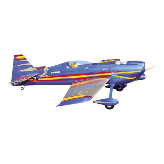
Specifications:
Wing span ---------------------------35.4in (90cm).
Wing area --------------226.3sq.in (14.6sq dm).
Weight ---------------- 1.9-2.1lbs (0.85-0.95kg).
Length -----------------------------30.4in (77.2cm).
Speed control(ESC)-------------15A-30A amp.
Motor -------------------------------------- 450-480.
Radio ----------- 4 channels with 5 mini servos.
Battery 3-cell 1800mAh to 2100mAh Li-Po.
1
10 x 5E Electric Prop.
Advertisement
Table of Contents

Related Manuals for Seagull Models Mini MXS-R EP


Summary of Contents for Seagull Models Mini MXS-R EP
- Page 1 www.seagullmodels.com MS: X128 ASSEMBLY MANUAL “Graphics and specifications may change without notice”. Specifications: Wing span ---------------------------35.4in (90cm). Wing area --------------226.3sq.in (14.6sq dm). Weight ---------------- 1.9-2.1lbs (0.85-0.95kg). Length -----------------------------30.4in (77.2cm). Speed control(ESC)-------------15A-30A amp. Motor -------------------------------------- 450-480. Radio ----------- 4 channels with 5 mini servos. Battery 3-cell 1800mAh to 2100mAh Li-Po.
-
Page 2: Kit Contents
Thank you for choosing the MINI MXS-R EP ARTF by SEAGULL MODELS COMPANY LTD. The MINI MXS-R EP was designed with the intermediate/advanced sport flyer in mind. It is a semi scale airplane which is easy to fly and quick to assemble. The airframe is conventionally built using balsa, plywood to make it stronger than the average ARTF , yet the design allows the aeroplane to be kept light. -
Page 3: Hinging The Ailerons
www.seagullmodels.com HINGING THE AILERONS . KIT CONTENTS. Fuselage Note: The control surfaces, including the Left wing panel ailerons, elevators, and rudder, are Right wing panel prehinged with hinges installed, but Fiberglass cowl the hinges are not glued in place. It Tail set is imperative that you properly Landing gear... -
Page 4: Hinging The Elevators
MINI MXS-R EP Instruction Manual. Hinge. 5) Turn the wing panel over and deflect the aileron in the opposite direction from the opposite side. Apply thin C/A glue to each hinge, making sure that the C/A penetrates into both the aileron and wing panel. - Page 5 www.seagullmodels.com INSTALL ELEVATOR CONTROL HORN. HINGING THE RUDDER. Glue the rudder hinges in place using the same techniques used to hinge the ailerons. Fiberglass control horn. Epoxy. Hinge. INSTALL THE AILERONS CONTROL HORN. Fiberglass control horn. fiberglass Elevator control horn. INSTALL RUDDER CONTROL HORN.
-
Page 6: Installing The Fuselage Servos
MINI MXS-R EP Instruction Manual. Elevator servo. Rudder servo. Rudder fiberglass control horn. FUSELAGE SERVO ARM INSTALLATION. INSTALLING THE FUSELAGE SERVOS. Install adjustable servo connector in the servo arm as same as picture below: Because the size of servos differ, you may need to adjust the size of the precut open- ing in the mount. - Page 7 www.seagullmodels.com 2) Follow diagram below for wheel pant installation: wheel. wheel collar. Washer. nut. Axle. wheel Pant. Lite-Plywood block. 4) A drop of C/A glue on the wheel collar screws will help keep them from coming lose during operation. Repeat the process for the other wheel. INSTALLING THE MAIN LANDING GEAR TO FUSELAGE.
- Page 8 MINI MXS-R EP Instruction Manual. Cut. Cut.
- Page 9 www.seagullmodels.com C/A glue. M3x10mm. C/A glue.
- Page 10 MINI MXS-R EP Instruction Manual. 4) Apply 2-3 drops of thin C/A to each of the INSTALLING THE AILERON. mounting holes. Allow the C/A to cure without using accelerator. Servos. Small weight. Thread. 5) Use dental floss to secure the connection so they cannot become unplugged.
- Page 11 www.seagullmodels.com 8) A string has been provided in the wing to pull the aileron lead through to the wing root. Remove the string from the wing at the servo location and use the tape to attach it to the servo extension lead. Pull the lead through the wing and remove the string.
- Page 12 MINI MXS-R EP Instruction Manual. ELECTRIC POWER ASSEMBLY. 1) Locate the items neccessary to install the electric power installation. 4mm. 15A-30A. 2) Attach the electric motor box to the firewall suitable with the cross lines drawn on the electric motor box and firewall. Using epoxy and balsa stick to secure the motor box to the firewall.Please see pictures below.
- Page 13 www.seagullmodels.com Because of the size of the cowl, it may be nec- 4) Locate the plywood battery tray to the essary to use a needle valve extension for the fuselage. high speed needle valve. Make this out of suf- ficient length 1mm wire and install it into the Battery.
-
Page 14: Installing The Spinner
MINI MXS-R EP Instruction Manual. INSTALLING THE SPINNER. Install the spinner backplate, propeller and spinner cone. Remove covering. 3) Put the stabilizer into place in the po- sition of the fuselage. 4) Install the stabilizer onto the fuselage. The propeller should not touch any part Align the centerline drawn on the top and the of the spinner cone. - Page 15 www.seagullmodels.com Pen. INSTALLING VERITICAL FIN. 7) Remove the stabilizer. Using the lines you just drew as a guide, carefully remove the covering from between them using a model- ing knife. Remove covering. 1) Using a modeling knife, remove the When cutting through the covering to re- covering from over the precut hinge slot cut move it, cut with only enough pressure into the lower rear portion of the fuselage.
- Page 16 MINI MXS-R EP Instruction Manual. 6) When you are sure that everything is aligned correctly, mix up a generous amount of Flash 30 Minute Epoxy. Apply a thin layer to the mounting slot in the top of the fuselage and to the sides and bottom of the vertical stabilizer mounting area.
- Page 17 www.seagullmodels.com Rudder pushrod. 75mm. Elevator control horn. Elevator control horn. AILERON PUSHROD HORN INSTALLATION Rudder control horn. Elevator pushrod. 30mm. 40mm. Elevator pushrod. 75mm. Repeat the procedure for other landing gear.
-
Page 18: Apply The Decals
1) A scale pilot is included with this ARF. The Seagull Pilot included fitting well to the cockpit. - Apply a bead of canopy glue around the inside (or you can order others scale pilot figures edge of the canopy. - Page 19 www.seagullmodels.com Tie wrap. Receiver. Battery. ATTACHMENT WING-FUSELAGE. BALANCING. Attach the carbon fiber tube into fuselage. 1) It is critical that your airplane be balanced correctly. Improper balance will cause your plane to lose control and crash. THE CENTER OF GRAVITY IS LOCATED 55MM BACK FROM THE LEADING EDGE OF THE WING AT THE WING ROOT.
-
Page 20: Control Throws
MINI MXS-R EP Instruction Manual. With the wing attached to the fuselage, all parts of the model installed ( ready to fly), and empty fuel tanks, hold the model at the 55mm. marked balance point with the stabilizer level.. Lift the model. If the tail drops when you lift, the model is “tail heavy”... -
Page 21: Flight Preparation
A) Plug in your radio system per the manufacturer's instructions and turn every- 2) Check every bolt and every glue joint in the MINI MXS-R EP to ensure that thing on. everything is tight and well bonded. B) Check the elevator first. Pull back on 3) Double check the balance of the air- the elevator stick.
Need help?
Do you have a question about the Mini MXS-R EP and is the answer not in the manual?
Questions and answers