Table of Contents
Advertisement
Quick Links
SIZE .75 - .91
MS:123
ASSEMBLY MANUAL
"Graphics a nd s pecifications m ay c hange w ithout n otice".
Specifications:
Wing span ----------------------------66.9in (170cm).
Wing area -----------------761.1sq.in (49.1sq dm).
Weight -------------------------------------9.3lbs (4.2kg).
Length ------------------------------51.1in (129.8cm).
Engine ------------------ 0.75-0.91cu.in ----2-stroke.
0.91-1
.25cu.in ---4-stroke.
Radio -------------------6 channels with 8 s ervos.
Retracts landing gear (included).
Electric conversion: optional
Advertisement
Table of Contents

Related Manuals for Seagull Models ZERO MS:123


Summary of Contents for Seagull Models ZERO MS:123
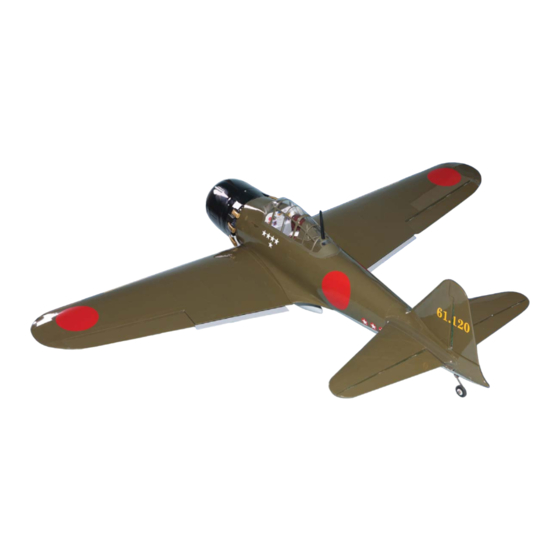
- Page 1 SIZE .75 - .91 MS:123 ASSEMBLY MANUAL “Graphics a nd s pecifications m ay c hange w ithout n otice”. Specifications: Wing span ----------------------------66.9in (170cm). Wing area -----------------761.1sq.in (49.1sq dm). Weight -------------------------------------9.3lbs (4.2kg). Length ------------------------------51.1in (129.8cm). Engine ------------------ 0.75-0.91cu.in ----2-stroke. 0.91-1 .25cu.in ---4-stroke.
-
Page 2: Kit Contents
ZERO. INTRODUCTION. Thank you for choosing the ZERO ARTF by SEAGULL MODELS. The ZERO was designed with the intermediate/advanced sport flyer in mind. It is a semi scale airplane which is easy to fly and quick to assemble. The airframe is conventionally built using balsa, plywood to make it stronger than the average ARTF , yet the design allows the aeroplane to be kept light. -
Page 3: Hinging The Ailerons
www.seagullmodels.com CONTEN.TS HINGING THE AILERONS . Note: The control surfaces, including the Fuselage ailerons, elevators, and rudder, are Left wing panel prehinged with hinges installed, but Right w ing p anel Tail s et ( 2) the hinges are not glued in place. It Canopy is imperative that you properly Aluminum wing tube... - Page 4 Instruction Manual. ZERO. Hinge. 4) Deflect the aileron and completely 5) Turn the wing panel over and deflect the saturate each hinge with thin C/A glue. The aileron in the opposite direction from the ailerons front surface should lightly contact the opposite side.
- Page 5 www.seagullmodels.com 3x35mm. 2 sets. Aileron control horn. 2) Position the control horn on the bottom of the aileron. You will see pre-drill hole 3mm for the horn mounting screw on the aileron. INSTALL FLAP CONTROL HORN. Install the flap control horn using the same method as same as the aileron control horns.
- Page 6 Instruction Manual. ZERO. C/A glue. Flap control horn. Hinge. INSTALL ELEVATOR CONTROL HORN. Install the elevator control horn using the same method as same as the aileron control horns. 3x35mm. 2 sets. T-pin. Hinge. 3mm. C/A glue.
-
Page 7: Engine Mount Installation
www.seagullmodels.com Elevator control horn. Balsa. Epoxy. ENGINE MOUNT INSTALLATION. 1) Locate the items necessary to install the engine mount included with your model. . 4x30mm. C/A glue. 2) Use four 4x30mm head bolts and four 4mm washers to attach the engine mount rails to the firewall. -
Page 8: Installing The Stopper Assembly
Instruction Manual. ZERO. Vent tube. Fuel pick up tube. Fuel fill tube. 3) Carefully bend the second nylon tube up at a 45º angle. This tube is the vent tube. 4) Test fit the stopper assembly into the tank. It may be necessary to remove some of INSTALLING THE STOPPER ASSEMBLY. -
Page 9: Installing The Fuselage Ser Vos
www.seagullmodels.com Fuel tank. 8) Use plywood template to hold in place the fuel tank with C/A glue to secure the fuel Blow through one of the lines to en- tank i nside t he f uselage. sure the fuel lines have not become kinked inside the fuel tank compartment. -
Page 10: Installing The Switch
Instruction Manual. ZERO. INSTALLING THE SWITCH. THROTTLE SERVO ARM INSTALLATION. Install the switch into the precut hole in the Install adjustable servo connector in the servo side, in the fuselage. arm as same as picture below: 3/ 32” Hole. Loctite secure. Adjustable Servo connector. - Page 11 www.seagullmodels.com 2) Use a pin drill and 4mm drill bit to drill a 7) Slide the throttle pushrod wire into the tube. small i ndentation i n t he mo unt f or t he e ngine Position the engine between the mounts. Use mounting screw.
- Page 12 Instruction Manual. ZERO. 4.5mm. 4) On the fire wall has the location for the + 0.91 - 1.25 : 4 STROKE. throttle pusshrod tube (pre-drill). 1) Position the engine with the drive washer (150mm) forward of the firewall as shown. Pushrod tube hole.
-
Page 13: Installing The Battery
www.seagullmodels.com INSTALLING THE BATTERY. Battery. 8) Reinstall the servo horn by sliding the connector over the pushrod wire. Center the Battery. throttle stick and trim and install the servo horn perpendicular to t he servo center line. Tie wrap. COWLING. 1) Slide the fiberglass cowl over the en- gine and line up the back edge of the cowl with 9) Move the throttle stick to the closed position... - Page 14 Instruction Manual. ZERO. Needle valve. Trim and cut. Machine screw M3x10mm. Because of the size of the cowl, it may be nec- essary to use a needle valve extension for the 3) Install the muffler and muffler extension high speed needle valve. Make this out of suf- onto the engine and make the cutout in the ficient length 1.5mm wire and install it into the cowl for muffler clearance.
- Page 15 www.seagullmodels.com Blind nut. 3mm. Epoxy. 5.2mm. Epoxy. 5.2mm.
-
Page 16: Installing The Spinner
Instruction Manual. ZERO. Epoxy. C/A glue. Electric motor. 4) Locate the plywood battery tray to the fuselage. Tighten the screws using machine screws M3x15mm to secure the tray in position. M4 x 15mm. Battery. 5) Attach the speed control to the side of the motor box using two-sided tape and tie wraps. -
Page 17: Installing The Aileron - Flap Servos
www.seagullmodels.com The propeller should not touch any part 3) Use drill bit in a pin vise to drill the mouting of the spinner cone. If it does, use a holes in the blocks. sharp modeling knife and carefully trim away the spinner cone where the propeller comes in contact with it. - Page 18 Instruction Manual. ZERO. 6) Secure the servo to the aileron hatch using 7) Apply 1-2 drops of thin C/A to each of the Phillips screwdriver and the screws provided mounting tabs. Allow the C/A to cure without with the servo. using accelerator.
- Page 19 www.seagullmodels.com M2x12mm. Aileron servo. M2x12mm. Flap servo. Small weight. Wing rib. Attach the string to the servo lead and String. carefully thread it though the wing. 8) A string has been provided in the wing to pull the aileron lead through to the wing root. Remove the string from the wing at the servo location and use the tape to attach it to the servo extension lead.
- Page 20 Instruction Manual. ZERO. 2) Make a 90-degree bend at the mark and cut AILERON PUSHROD HORN INSTALLATION off the excess wire leaving 8mm past the bend. Metal clevis. M2 lock nut. Pen. Snap keeper. Mark. Servo arm. 1) Mark the control wire where it crosses the Snap keeper.
-
Page 21: Landing Gear
www.seagullmodels.com INSTALLING THE FLAP PUSHROD. Repeat the procedure for the aileron pushrod. Wing. M2 lock nut. Cut. 3) Glue hardwood mounting blocks into the wing as show with epoxy. Flap. Epoxy. INSTALLING RETRACTABLE LANDING GEAR. 1) Locate the items necessary to install the retracts landing gear and retract linkage instal- lation. - Page 22 Instruction Manual. ZERO. 5) Install the linkage into the connector on the end of the retract unit as shown. Mounting the landing gear to the rail with four M3x 2.5mm. M3x25mm. 6) Install a wheel and two wheel collars on the main landing gear.
- Page 23 www.seagullmodels.com SERVO GEAR 4.5KG (35X16X30MM). Epoxy. Epoxy. 8) Install the gear door to the retract strut. Apply a thin epoxy to the two gear door brack- ets to secure the gear door to the retract strut as shown. Epoxy. Loctite secure. Adjustable Servo connector.
-
Page 24: Mounting The T Ail Wheel
Instruction Manual. ZERO. M3x25mm. Screw. Screw. M3x15mm. MOUNTING THE T AIL WHEEL. M3x15mm. INSTALLING THE HORIZONTAL STABILIZER. 1) Using a ruler and a pen, locate the centerline of the horizont al stabilizer, at the trailing edge, and place a mark. Use a triangle and extend this mark, from back to front, across the top of the st abilizer. - Page 25 www.seagullmodels.com 2) Using a modeling knife, carefully remove the covering at mounting slot of horizontal stabilizer. Remove the covering. 3) Put the stabilizer into place in the position of the fuselage. 4) Install the stabilizer onto the fuselage. Remove the covering. Align the centerline drawn on the top and the rear of the stabilizer with the centre of the fu- selage.
-
Page 26: Installing The Vertical Stabilizer
Instruction Manual. ZERO. Fill epoxy. While holding the vertical stabilizer firmly in place, use a pen and draw a line on each side of the vertical stabilizer where it meets the top of the fuselage. Fill epoxy. Fill epoxy. 3) Slide the v ertical stabilizer back in place. -
Page 27: Hinging The Elevator
www.seagullmodels.com 4) When you are sure that everything is aligned correctly, mix up a generous amount of Flash 30 Minute Epoxy. Apply a thin layer to the mounting slot and to bottom of the vertical sta- bilizer mounting area. Apply epoxy to the bot- tom and top edges of the filler block and to the lower hinge also. -
Page 28: Hinging The Rudder
Instruction Manual. ZERO. HINGING THE RUDDER. Glue the rudder hinges in place using the same techniques used to hinge the ailerons. C/A glue. Epoxy. - Page 29 www.seagullmodels.com Screw. C/A glue.
- Page 30 Instruction Manual. ZERO. ELEVATOR PUSHROD HORN INSTALLATION. 1) Install the elevator control horn using the same method as with the aileron control horns. 2) Position the elevator control horn on the both side of elevator . Elevator pushrod. Screw. Elevator control horn. 3) Thread one clevis and M2 lock nut on to each elevator control rod.
- Page 31 www.seagullmodels.com 8mm. C/A glue. Pen. RUDDER PUSHROD HORN INSTALLATION. 8mm. Cut. M2 lock nut . M2 clevis. 8mm.
- Page 32 Instruction Manual. ZERO. 2) A scale pilot is included with this ARF. The Seagull Pilot included fitting well to the cockpit. (or you can order others scale pilot figures made by Seagull factory . They are available at Seagull distributors.) If you are going to install a pilot figure, please use a sanding bar to sand the base of the figure so that it is flat.
-
Page 33: Install The Plastic Parts
www.seagullmodels.com INSTALL THE PLASTIC PARTS. Epoxy. 4) Position the canopy onto the fuselage. Trace around the canopy and onto the fuselage using a felt-tipped pen. - Apply a bead of canopy glue around the inside edge of the canopy . Position the canopy onto the hatch. -
Page 34: Apply The Decals
Instruction Manual. ZERO. ATTACHMENT WING-FUSELAGE. C/A glue. Attach the aluminium tube into fuselage. Wing tube. APPLY THE DECALS. 1) If all the decals are precut and ready to Insert two wing panels as pictures below. stick. Please be certain the model is clea n and free from oily fingerprints and dust. - Page 35 www.seagullmodels.com Open Position. servo arm. Close Position. 12mm. servo arm.
-
Page 36: Control Throws
Instruction Manual. ZERO. Lift the model. If the tail drops when you lift, BALANCING. the model is “tail heavy” and you must add 1) It is critical that your airplane be weight* to the nose. If the nose drops, it is balanced correctly. -
Page 37: Flight Preparation
www.seagullmodels.com FLIGHT PREPARATION. PREFLIGHT CHECK. Check the operation and direction of the 1) Completely charge your transmitter elevator, rudder, ailerons and throttle. and receiver batteries before your first day of flying. A) Plug in your radio system per the manufacturer's instructions and turn every- 2) Check every bolt and every glue joint thing on.
Need help?
Do you have a question about the ZERO MS:123 and is the answer not in the manual?
Questions and answers