Table of Contents
Advertisement
Quick Links
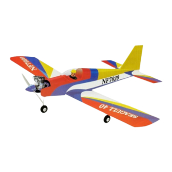
Hand-made Almost Ready to Fly R/C Model Aircraft
"Graphics and specfications may change without notice".
Specifications
Wingspan ------------------------------------------ 60 in/ 153cm.
Wing area ------------------------------------ 620 sq.in/ 40dm
Length -------------------------------------------- 45 in/ 113.7cm.
Approximate flying weight --------- 5.5 - 6.2 lbs/ 2.5-2.8kg.
Recommended engine size - 0.40 -- 0.46 cu. in 2-stroke.
Recommended R/C ------------------- 4 channel minimum.
Flying skill level ----------------------------- Low wing Trainer.
Kit features.
•
Ready-made-minimal assembly & finishing required.
•
Factory-installed pushrod.
•
Photo-illustrated step-by-step Assembly Manual.
SEAGU LL 4 0
LOW WI N G T RAI N ER
ASSEM BLY M AN UAL
2
.
0.52 cu. in 4-stroke.
Additional items required.
Engine.
4 Channel or greater Radio Control system.
Glues.
Tools.
Starting Equipment.
Made in Vietnam.
MS:10
Advertisement
Table of Contents

Subscribe to Our Youtube Channel
Related Manuals for Seagull Models Low Wing Sport V2 10cc ARF


Summary of Contents for Seagull Models Low Wing Sport V2 10cc ARF
- Page 1 SEAGU LL 4 0 LOW WI N G T RAI N ER Hand-made Almost Ready to Fly R/C Model Aircraft MS:10 ASSEM BLY M AN UAL “Graphics and specfications may change without notice”. Specifications Additional items required. Wingspan ------------------------------------------ 60 in/ 153cm. Engine.
-
Page 2: Wing Assembly
SEAGU LL 4 0 Instruction Manual. LOW WING TRAINER. INTRODUCTION. Thank you for choosing the SEAGULL 40 ARTF by SG MODELS. The LOW WING TRAINER SEAGULL 40 was designed with the intermediate/advanced sport flyer in mind. It is a low-wing aeroplane which is easy to fly and quick to assemble. -
Page 3: Installing The Aileron Servos
2) Remove the brace when satisfied with 3) Peel off the backing from the self adhe- its fit ineach wing half. Coat both sides of one sive covering strip. Apply the strip to the centre half of the dihedral brace with 30 minute epoxy. section of the wing starting from the bottom Next, pour some epoxy into the dihedral box in trailing edge. - Page 4 SEAGU LL 4 0 Instruction Manual. LOW WING TRAINER. String. Small weight. Thread. Small weight. Wing bottom. Thread. 4) Tape the servo lead to the wing to pre- vent it from falling back into the wing. Plastic tape. 3) Attach servo lead to the aileron servo. Attach the string to the servo lead and care- fully thread it though the wing.
-
Page 5: Aileron Linkage
Repeat the procedure for the other wing half. Control Horn. AILERON LINKAGE. 1) Using a ruler & pen to draw a straight line as below picture. Mounting Screws. Mounting Plate. 4) Using a 1mm drill bit and the control horns as a guide, drill the mounting holes through the aileron halves. -
Page 6: Installing The Main Gear Wires
SEAGU LL 4 0 Instruction Manual. LOW WING TRAINER. 3x10mm. Cut. 1) Using a modeling knife, remove the 8) Make a 90-degree bend at the mark covering from over the two main gear mount- and cut off the excess wire leaving 10mm past ing slots located in the bottom of the wing. -
Page 7: Installing The Stopper Assembly
INSTALLING THE STOPPER ASSEMBLY. Pen. 1) Using a modeling knife, carefully cut off the rear portion of one of the two nylon tubes leaving 1/2” protruding from the rear of the stopper. This will be the fuel pick up tube. 2) Using a modeling knife, cut one length of silicon fuel line (not included) to 2-1/4”... -
Page 8: Mounting The Engine
SEAGU LL 4 0 Instruction Manual. LOW WING TRAINER. 5) Test fit the stopper assembly into the tank. It may be necessary to remove some of the flashing around the tank opening using a modeling knife. If flashing is present, make sure none falls into the tank. -
Page 9: Nose Gear Installation
112mm. NOSE GEAR INSTALLATION. 2.5mm. 3x25mm. 5) Bolt the engine to the engine mount using the four machine screws. Double check that all the screws are tight before proceeding. 6) Attach the Z-Bend in the pushrod wire to the throttle arm on the carburetor. Installing steering arm as below. -
Page 10: Installing The Switch
SEAGU LL 4 0 Instruction Manual. LOW WING TRAINER. Install the pushrod wire as shown. Adjustable Connector. NOTE : IF YOU ASSEMBLE WITH ELECTRIC POWER ENGINE,PLEASE SEE PAGE 16. INSTALLING THE SPINNER. INSTALLING THE SWITCH. Install the spinner backplate, propeller and 1) Install the switch into the precut hole spinner cone. -
Page 11: Horizontal Stabilizer
Secure the servos with the screws pro- vided from your radio system. 2) Position the servos into the servo tray with the output shafts orientated as shown below. Drill 1/16” pilot holes through the tray for each of the mounting screws. Throttle. -
Page 12: Vertical Stabilizer Installation
SEAGU LL 4 0 Instruction Manual. LOW WING TRAINER. 2) Slide the vertical stabilizer into the slot 7) When you are sure that everything is in the top of the fuselage. The rear edge of aligned correctly, mix up a generous amount the stabilizer should be flush with the rear edge of 30 Minute Epoxy. -
Page 13: Control Horn Installation
When cutting through the covering to re- move it, cut with only enough pressure to only cut through the covering itself. Cutting into the balsa structure may weaken it. 5) Slide the vertical stabilizer back in place. Using a triangle, check to ensure that the vertical stabilizer is aligned 90º... - Page 14 SEAGU LL 4 0 Instruction Manual. LOW WING TRAINER. ELEVATOR-RUDDER PUSHROD Antenna wire. INSTALLATION. Elevator pushrod. Control horn. Rudder pushrod. Clevis. Antenna. Battery. Tie wrap. Adjustable Servo connector. Servo arm. Receiver. (1 PCS). ATTACHMENT WING - FUSELAGE. (2 PCS). Thread locker glue. See picture below: Rudder.
-
Page 15: Flight Preparation
INITIAL FLYING/SPORT FLYING If the nose of the plane falls, the plane Ailerons: 3/8” up 3/8” down is nose heavy. To correct this first move the Elevator: 3/8 ” up 3/8” down battery pack further back in the fuselage. If Rudder: 1/2”... -
Page 16: Preflight Check
PREFLIGHT CHECK. ELECTRIC POWER CONVERSION. 1) Completely charge your trans- 1) Locate the items neccessary to install mitter and receiver batteries before the electric power conversion included your irst day of lying. with your model. 2) Check every bolt and every glue joint in the SEAGULL 40 to ensure that everything is tight and well bond- 3) Double check the balance of the... - Page 17 Instruction Manual. 4x20 mm 4) Attach the motor to the front of the electric motor box using four 4mm blind nut, four M3x15mm hex head bolts to se- cure the motor. Please see picture shown. M3x15mm Epoxy 4 mm 112mm...
- Page 18 M3x15mm Speed control. Air exit hole. COWLING. Battery. Please see below pictures.
-
Page 19: Installing The Spinner
Instruction Manual. INSTALLING THE SPINNER. 2 mm he propeller should not touch any part of the spinner cone. If it does, use a sharp modeling knife and carefully trim away the spinner cone where the propel- ler comes in contact with it. 3x10mm We wish you many safe and enjoyable lights with your...
Need help?
Do you have a question about the Low Wing Sport V2 10cc ARF and is the answer not in the manual?
Questions and answers