Table of Contents
Advertisement
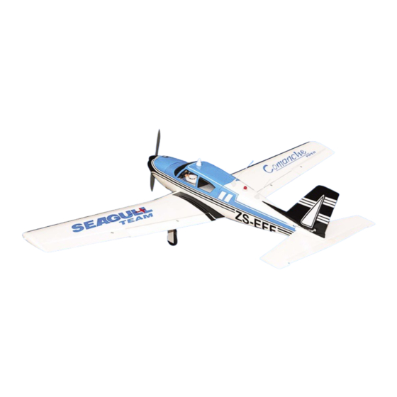
MS:142
ASSEMBLY MANUAL
"Graphics and specifications may change without notice".
Specifications:
Wing span ------------------------------72in (183cm).
Wing area -----------------768.8sq.in (49.6sq dm).
Weight ------------------------8.8-9.7lbs (4.0-4.4kg).
Length ------------------------------46.3in (117.7cm).
Engine ------------------ 0.61-0.75cu.in -----2-stroke.
0.91-1.00cu.in -----4-stroke.
Radio ------------------- 6 channels with 7 servos.
Electric conversion: optional
Retracts landing gear (excluded) - optional.
Advertisement
Table of Contents

Related Manuals for Seagull Models Piper Comanche MS:142


Summary of Contents for Seagull Models Piper Comanche MS:142
- Page 1 MS:142 ASSEMBLY MANUAL “Graphics and specifications may change without notice”. Specifications: Wing span ------------------------------72in (183cm). Wing area -----------------768.8sq.in (49.6sq dm). Weight ------------------------8.8-9.7lbs (4.0-4.4kg). Length ------------------------------46.3in (117.7cm). Engine ------------------ 0.61-0.75cu.in -----2-stroke. 0.91-1.00cu.in -----4-stroke. Radio ------------------- 6 channels with 7 servos. Electric conversion: optional Retracts landing gear (excluded) - optional.
-
Page 2: Kit Contents
PIPER COMANCHE INTRODUCTION. Thank you for choosing the PIPER COMANCHE ARTF by SEAGULL MODELS COMPANY LTD. The PIPER COMANCHE was designed with the intermediate/advanced sport flyer in mind. It is a semi scale airplane which is easy to fly and quick to assemble. The airframe is conventionally built using balsa, plywood to make it stronger than the average ARTF , yet the design allows the aeroplane to be kept light. -
Page 3: Additional Items Required
www.seagullmodels.com CONTEN.TS HINGING THE FLAP . SEA14201 Fuselage Note: The control surfaces, including the SEA14202 Wing Set ailerons, elevators, and rudder, are SEA14203 Tail Set SEA14204 Cowling prehinged with hinges installed, but SEA14205 Main Gear the hinges are not glued in place. It SEA14206 Nose Gear is imperative that you properly... -
Page 4: Hinging The Aileron
Instruction Manual. PIPER COMANCHE 8) After both flap are securely hinged, firmly grasp the wing panel and flap to make sure the hinges are securely glued and cannot be pulled out. Do this by carefully applying medium pressure, trying to separate the flap from the wing panel. - Page 5 www.seagullmodels.com T-pin. Hinge. C/A glue. 3) Slide the aileron on the wing panel until there is only a slight gap. The hinge is now centered on the wing panel and aileron. Remove the T-pins and snug the aileron against the wing panel. A gap of 1/64” or less should be maintained between the wing panel and aileron.
-
Page 6: Hinging The Elevator
Instruction Manual. PIPER COMANCHE 8) After both ailerons are securely hinged, WING TIP ASSEMBLY. firmly grasp the wing panel and aileron to make sure the hinges are securely glued and Covering. cannot be pulled out. Do this by carefully applying medium pressure, trying to separate the aileron from the wing panel. - Page 7 www.seagullmodels.com CONTROL HORN M3 SCREW. Epoxy. ALUMINUM WASHER Wing M3 LOCK NUT ALUMINUM WASHER INSTALL THE AILERONS CONTROL HORN. Wing 1) Locate the hardware necessary to install the control horns for the ailerons. 18mm Epoxy 2 sets. 3x40mm. 2) Position the control horn on the bottom of the aileron.
-
Page 8: Horizontal Stabilizer
Instruction Manual. PIPER COMANCHE INSTALL ELEVATOR CONTROL HORN. Install the elevator control horn using the same method as same as the aileron control horns. 1 sets. 3mm. 3x35mm. CONTROL HORN M3 SCREW. Epoxy. ALUMINUM WASHER 3mm. M3 LOCK NUT ALUMINUM WASHER CONTROL HORN M3 SCREW. -
Page 9: Engine Mount Installation
www.seagullmodels.com Epoxy. Rudder Fuselage 16mm Elevator control horn. INSTALL RUDDER CONTROL HORN. Repeat steps to install the rudder control horn as same as steps done for ailerons. Rudder control horn. 1 sets. ENGINE MOUNT INSTALLATION. 1) Locate the items necessary to install the engine mount included with your model. -
Page 10: Installing The Stopper Assembly
Instruction Manual. PIPER COMANCHE Thread locker glue. Vent tube. Fuel pick up tube. INSTALLING THE STOPPER ASSEMBLY. 1) Using a modeling knife, carefully cut Fuel fill tube. off the rear portion of one of the 3 nylon tubes leaving 1/2” protruding from the rear of the stopper. -
Page 11: Fuel Tank Installation
www.seagullmodels.com 9) Connect the lines from the tank to the engine FUEL TANK INSTALLATION. and muffler. The vent line will connect to the muffler and the line from the clunk to the carburetor. You should mark which tube is the vent and which is the fuel pickup when you attach fuel tubing to the tubes in the stopper. -
Page 12: Mounting The Engine
Instruction Manual. PIPER COMANCHE MOUNTING THE ENGINE. Loctite secure. Adjustable Servo 1) Position the engine with the drive washer connector. (150mm) forward of the firewall as shown. Servo arm. 1 PCS. Throttle servo arm. 140mm. 2) Use a pin drill and 2mm drill bit to drill a small indentation in the mount for the engine Rudder servo arm. -
Page 13: Landing Gear Installation
www.seagullmodels.com Pushrod tube hole. 5) Slide the pushrod tube in the firewall and 9) Move the throttle stick to the closed position guide it through the fuel tank mount. Use and move the carburetor to closed. Use a 2.5mm medium C/A to glue the tube to the firewall and hex wrench to tighten the screw that secures the fuel tank mount. - Page 14 Instruction Manual. PIPER COMANCHE Trim and cut. M2 clevis. Trim and cut. Adjustable connector. Trim and cut. Because of the size of the cowl, it may be nec- essary to use a needle valve extension for the high speed needle valve. Make this out of suf- COWLING.
- Page 15 www.seagullmodels.com 3) Install the muffler and muffler extension onto the engine and make the cutout in the cowl for muffler clearance. Connect the fuel and pressure lines to the carburetor, muffler and fuel filler valve. Secure the cowl to fuse- lage using the M3x10mm screws.
- Page 16 Instruction Manual. PIPER COMANCHE Blind nut. M4x20mm. 3) Attach the motor to the front of the electric motor box using four 3mm blind nut, four M3x15mm hex head bolts to secure the motor. Please see picture shown. M3x15mm. 4mm. Epoxy. 140mm.
-
Page 17: Installing The Aileron - Flap Servos
www.seagullmodels.com 4) Locate the plywood battery tray to the fuselage. Tighten the screws using machine screws M3x15mm to secure the tray in position. Battery. The propeller should not touch any part of the spinner cone. If it does, use a sharp modeling knife and carefully trim away the spinner cone where the propeller comes in contact with it. - Page 18 Instruction Manual. PIPER COMANCHE 2) Place the servo between the mounting blocks and space it from the hatch. Use a pencil to mark the mounting hole locations on the blocks. 7) Apply 1-2 drops of thin C/A to each of the mounting tabs.
- Page 19 www.seagullmodels.com 9) Set the aileron hatch in place and use a Phillips screw driver to install it with four wood screws. AILERON PUSHROD HORN INSTALLATION...
- Page 20 Instruction Manual. PIPER COMANCHE 60mm. Wing. M2 lock nut. M3 clevis. M3 lock nut. 100mm. Aileron. Flap Wing Wing Flap Repeat the procedure for the other aileron servo. INSTALLING THE FLAP SERVO. Repeat the procedure for the aileron servo. Wing. M2 lock nut.
- Page 21 www.seagullmodels.com 2mm. Screw. 2mm. Epoxy. M3x25mm. Epoxy.
-
Page 22: Installing The Horizontal Stabilizer
Instruction Manual. PIPER COMANCHE INSTALLING THE HORIZONTAL STABILIZER. Epoxy. 1) Using a ruler and a pen, locate the centerline of the horizontal stabilizer, at the trail- ing edge, and place a mark. Use a triangle and extend this mark, from back to front, across the top of the stabilizer. - Page 23 www.seagullmodels.com Pen. INSTALLING VERITICAL FIN. 5) Remove the stabilizer. Using the lines you just drew as a guide, carefully remove the covering from between them using a model- ing knife. Trim and cut. When cutting through the covering to re- move it, cut with only enough pressure 1) Using a modeling knife, remove the to only cut through the covering itself.
- Page 24 Instruction Manual. PIPER COMANCHE Fill epoxy. 3) Slide the vertical stabilizer back in place. Using a triangle, check to ensure that the vertical stabilizer is aligned 90º to the hori- zontal stabilizer. ELEVATOR - RUDDER PUSHROD HORN INSTALLATION. Vertical Stabilizer. 1) Install the elevator control horn using Horizontal 90º...
- Page 25 www.seagullmodels.com 580mm. M2 clevis. M2 lock nut. 620mm. Control horn. Elevator pushrod. Rudder pushrod. C/A glue. Metal clevis. M2 lock nut. Elevator pushrod. Elevator pushrod. C/A glue. 520mm. M2 clevis. M2 lock nut. 560mm. Control horn. Rudder pushrod. M2 lock nut. Metal clevis.
- Page 26 Instruction Manual. PIPER COMANCHE If you are going to install a pilot figure, please use a sanding bar to sand the base of the figure C/A glue. so that it is flat. 3) Position the pilot figure on the canopy floor as show.
-
Page 27: Apply The Decals
www.seagullmodels.com APPLY THE DECALS. ATTACHMENT WING-FUSELAGE. Attach the aluminium tube into fuselage. 1) If all the decals are precut and ready to stick. Please be certain the model is clean and free from oily fingerprints and dust. Position decal on the model where desired, using the photos on the box and aid in their location. - Page 28 Instruction Manual. PIPER COMANCHE BALANCING. 1) It is critical that your airplane be balanced correctly. Improper balance will cause your plane to lose control and crash. THE CENTER OF GRAVITY IS LOCATED 110 MM BACK FROM THE LEADING EDGE OF THE WING AT THE WING ROOT. 2) Mount the wing to the fuselage.
-
Page 29: Control Throws
www.seagullmodels.com CONTROL THROWS. Ailerons: 12mm - 15mm up 110mm. 12mm - 15mm down. Elevator: 12mm - 15mm up. 12mm - 15mm down. Rudder: 20mm - 30mm left. 20mm - 30mm right. *If possible, first attempt to balance the model by changing the position of the receiver battery and receiver. -
Page 30: Flight Preparation
Instruction Manual. PIPER COMANCHE PREFLIGHT CHECK. FLIGHT PREPARATION. 1) Completely charge your transmitter Check the operation and direction of the and receiver batteries before your first day of elevator, rudder, ailerons and throttle. flying. 2) Check every bolt and every glue joint A) Plug in your radio system per the in the PIPER COMANCHE to ensure that manufacturer's instructions and turn every-...
Need help?
Do you have a question about the Piper Comanche MS:142 and is the answer not in the manual?
Questions and answers