Table of Contents
Advertisement
Quick Links
"Graphics and specifications may change without notice".
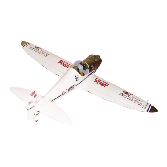
The Seagull "Silence Twister" is a scale model of a home
built aircraft which is currently in production by the Silence
Aircraft factory in Germany. With it's unique elliptical wing
shape which is very reminiscent of the famous Spitfire,
the Twister captures the magnificent aerobatic
characteristics of the Spitfire with the appearance and
performance of a modern day pleasure craft. Carefully
manufactured from Balsa & Plywood, the Seagull "Silence
Twister" is lightweight, strong, easy to repair and lots fun
to fly.
ASSEMBLY MANUAL
Specifications:
Wing span ----------------------------66.9in (170cm).
Wing area -----------------691.3sq.in (44.6sq dm).
Weight ----------------------8.8-10.6lbs (4.0-4.8kg).
Length ------------------------------53.3in (135.3cm).
Engine ---------------------- 0.91cu.in ----2-stroke.
0.91-1.10-1.25cu.in ----4-stroke.
Radio --------------------6 channels with 9 servos.
Retracts landing gear (included) - optional.
Electric conversion: optional
MS:140
Advertisement
Table of Contents

Related Manuals for Seagull Models Silence Twister


Summary of Contents for Seagull Models Silence Twister
- Page 1 “Graphics and specifications may change without notice”. Specifications: Wing span ----------------------------66.9in (170cm). The Seagull “Silence Twister” is a scale model of a home Wing area -----------------691.3sq.in (44.6sq dm). built aircraft which is currently in production by the Silence Aircraft factory in Germany. With it’s unique elliptical wing Weight ----------------------8.8-10.6lbs (4.0-4.8kg).
-
Page 2: Kit Contents
You will find that most of the work has been done for you already.The motor mount has been fitted and the hinges are pre-installed . Flying the SILENCE TWISTER is simply a joy. This instruction manual is designed to help you build a great flying aeroplane. Please read this manual thoroughly before starting assembly of your SILENCE TWISTER . -
Page 3: Additional Items Required
www.seagullmodels.com KIT CONTENTS. INSTALLING LED LIGHTING SYSTEM. Fuselage Canopy Left wing panel Right wing panel Tail set Aluminum wing tube Scale pilot Fiberglass cowl Main landing gear EP conversion pack Hardware bag included 4.8v led lights. ADDITIONAL ITEMS REQUIRED. C/A glue. 0.75-0.91 2-stroke. -
Page 4: Hinging The Ailerons
Instruction Manual. SILENCE TWISTER Hinge. 2) Remove each hinge from the wing panel and aileron and place a T-pin in the center of each hinge. Slide each hinge into the aileron until the T-pin is snug against the aileron. This... -
Page 5: Hinging The Elevator
www.seagullmodels.com 7) Repeat this process with the other wing The hinge is constructed of a special Note: panel, securely hinging the aileron in place. material that allows the C/A to wick penetrate distribute 8) After both ailerons are securely hinged, throughout the hinge, securely firmly grasp the wing panel and aileron to bonding it to the wood structure of... - Page 6 Instruction Manual. SILENCE TWISTER INSTALL THE AILERONS CONTROL HORN. Epoxy. Epoxy. Epoxy. Flap control horn. INSTALL ELEVATOR CONTROL HORN. Epoxy. Aileron control horn. INSTALL FLAP CONTROL HORN. Epoxy.
-
Page 7: Engine Mount Installation
www.seagullmodels.com ENGINE MOUNT INSTALLATION. 1) Locate the items necessary to install the engine mount included with your model. . Elevator control horn. M4x30mm. INSTALL RUDDER CONTROL HORN. 2) Use four M4x30mm head bolts and four 4mm washers to attach the engine mount rails to the firewall. - Page 8 Instruction Manual. SILENCE TWISTER Blind nut. 5.5mm. Thread locker glue. 5.5mm. Blind nut. + 0.91 - 1.20 : 4 STROKE. Thread locker glue.
-
Page 9: Installing The Stopper Assembly
www.seagullmodels.com Vent tube. Fuel pick up tube. INSTALLING THE STOPPER ASSEMBLY. Fuel fill tube. 1) Using a modeling knife, carefully cut off the rear portion of one of the 3 nylon tubes 3) Carefully bend the second nylon tube leaving 1/2” protruding from the rear of the up at a 45º... -
Page 10: Installing The Fuselage Servos
Instruction Manual. SILENCE TWISTER Rudder servo. Fuel tank. Tie wrap. Throttle servo. Elevator servo. THROTTLE SERVO ARM INSTALLATION. Fuel tank. Install adjustable servo connector in the servo arm as same as picture below: Loctite secure. C/A glue. Adjustable Servo connector. -
Page 11: Installing The Switch
www.seagullmodels.com Rudder servo arm. Trim and cut. Elevator servo arm. Throttle servo arm. INSTALLING THE SWITCH. Install the switch into the precut hole in the side, in the fuselage. 3/ 32” Hole. Switch. INSTALLING THE AILERON - FLAP SERVOS. Servos. Small weight. - Page 12 Instruction Manual. SILENCE TWISTER 2) Place the servo between the mounting 6) Secure the servo to the aileron hatch using blocks and space it from the hatch. Use a pencil Phillips screwdriver and the screws provided to mark the mounting hole locations on the with the servo.
-
Page 13: Mounting The Engine
www.seagullmodels.com Aileron servo. Flap servo. MOUNTING THE ENGINE. + ENGINE .75 - .91 : 2 STROKE. 1) Position the engine with the drive washer (140mm) forward of the firewall as shown. 140mm. 2) Use a pin drill and 4mm drill bit to drill a small indentation in the mount for the engine mounting screw. - Page 14 Instruction Manual. SILENCE TWISTER 4mm. 3) Use a drill to drill the four holes in the engine 8) Reinstall the servo horn by sliding the mount rails. connector over the pushrod wire. Center the throttle stick and trim and install the servo horn perpendicular to the servo center line.
- Page 15 www.seagullmodels.com + ENGINE .91 - 1.2 : 4 STROKE. 1) Position the engine with the drive washer (150mm) forward of the firewall as shown. 4.5mm. 5) Slide the pushrod tube in the firewall and guide it through the fuel tank mount. Use medium C/A to glue the tube to the firewall and 150mm.
- Page 16 Instruction Manual. SILENCE TWISTER Trim and cut. 9) Move the throttle stick to the closed position and move the carburetor to closed. Use a 2.5mm hex wrench to tighten the screw that secures the throttle pushrod wire. Make sure to use threadlock on the screw so it does not vibrate loose.
- Page 17 www.seagullmodels.com Trim and cut. 3) Install the muffler and muffler extension onto the engine and make the cutout in the Trim and cut. cowl for muffler clearance. Connect the fuel and pressure lines to the carburetor, muffler and fuel filler valve. Secure the cowl to fuse- lage using the M3x10mm screws.
- Page 18 Instruction Manual. SILENCE TWISTER ELECTRIC POWER CONVERSION. 1) Locate the items neccessary to install the electric power conversion included with your model. - Model size: .75-.90 size models - Motor: 50mm 310 rev per volt - Propeller: 14x10 ~ 15x10...
- Page 19 www.seagullmodels.com 5.2mm. Blind nut. 5.2mm. Blind nut. M4x20mm. 3) Attach the motor to the front of the electric motor box using four 4mm blind nut, four M3x15mm hex head bolts to secure the motor. Please see picture shown. 4mm. M3x15mm.
-
Page 20: Installing The Spinner
Instruction Manual. SILENCE TWISTER INSTALLING THE SPINNER. Install the spinner backplate, propeller and spinner cone. 140mm. Balsa stick. The propeller should not touch any part of the spinner cone. If it does, use a sharp modeling knife and carefully trim away the spinner cone where the propeller comes in contact with it. - Page 21 www.seagullmodels.com Cut. Pen. Remove the covering. 3) Put the stabilizer into place in the 7) Remove the stabilizer. Using the lines position of the fuselage. you just drew as a guide, carefully remove the covering from between them using a model- 4) Install the stabilizer onto the fuselage.
-
Page 22: Installing The Vertical Stabilizer
Instruction Manual. SILENCE TWISTER Epoxy. Fill epoxy. While holding the vertical stabilizer firmly in place, use a pen and draw a line on each side of the vertical stabilizer where it Epoxy. meets the top of the fuselage. Epoxy. 10) After the epoxy has fully cured, re- move the masking tape or T-pins used to hold the stabilizer in place. - Page 23 www.seagullmodels.com 4) When you are sure that everything is aligned correctly, mix up a generous amount of Flash 30 Minute Epoxy. Apply a thin layer to the mounting slot and to bottom of the vertical sta- bilizer mounting area. Apply epoxy to the bot- tom and top edges of the filler block and to the lower hinge also.
- Page 24 Instruction Manual. SILENCE TWISTER 2) Make a 90-degree bend at the mark and cut 3) Connect the linkage as shown and secure off the excess wire leaving 8mm past the bend. the control wire with a snap keeper. Metal clevis.
- Page 25 www.seagullmodels.com M3x25mm. C/A glue. M3x4mm.
- Page 26 Instruction Manual. SILENCE TWISTER 495mm. Cut. ELEVATOR PUSHROD HORN INSTALLATION. 1) Install the elevator control horn using the same method as with the aileron control horns. 2) Position the elevator control horn on the both side of elevator. Rudder control horn.
- Page 27 www.seagullmodels.com Wire keeper. 8mm. 8mm. RUDDER PUSHROD HORN INSTALLATION. M2 lock nut . M2 clevis. 8mm. Pen. Elevator control horn. Rudder control horn. 8mm.
- Page 28 Instruction Manual. SILENCE TWISTER Wire keeper. Elevator pushrod. Control horn. M2 lock nut. Metal clevis. Rudder pushrod. Pen. Cut. 8mm.
- Page 29 www.seagullmodels.com INSTALLING RETRACTABLE LANDING GEAR (OPTIONAL). Cut. 1) Locate the items necessary to install the retracts landing gear and retract linkage instal- lation (included). 1.5mm. 200mm. 1.5mm. 220mm. 2) Cut the covering from the bottom of the wing for retracts landing gear installation. M3x12mm.
- Page 30 Instruction Manual. SILENCE TWISTER Epoxy. 200mm. 220mm. Epoxy. Metal clevis.
-
Page 31: Apply The Decals
www.seagullmodels.com Repeat the procedure for the other wing. Epoxy. C/A glue. M2x6mm. APPLY THE DECALS. Epoxy. 1) If all the decals are precut and ready to stick. Please be certain the model is clean and free from oily fingerprints and dust. Position decal on the model where desired, using the photos on the box and aid in their location. - Page 32 Instruction Manual. SILENCE TWISTER Insert two wing panels as pictures below. INSTALLING THE BATTERY - RECEIVER. 1) Plug the five servo leads and the switch lead into the receiver. Plug the battery pack lead into the switch also. 2) Wrap the receiver and battery pack in the protective foam rubber to protect them from vibration.
- Page 33 www.seagullmodels.com Accurately mark the balance point on the top of the wing on both sides of the fuselage. The balance point is located 110 mm back from the leading edge of the wing at the wing root. This is the balance point at which your model should balance for your first flights.
-
Page 34: Control Throws
Instruction Manual. SILENCE TWISTER CONTROL THROWS. INITIAL FLYING/SPORT FLYING. Ailerons: 10mm up 10mm down. Elevator: 15mm up 15mm down. Rudder: 10mm left 10mm right. AEROBATIC FLYING. Ailerons: 15mm up 15mm down. Elevator: 20mm up 20mm down. Rudder: 15mm left 15mm right. -
Page 35: Flight Preparation
A) Plug in your radio system per the 2) Check every bolt and every glue joint manufacturer's instructions and turn every- in the SILENCE TWISTER to ensure that thing on. everything is tight and well bonded. B) Check the elevator first. Pull back 3) Double check the balance of the air- on the elevator stick.
Need help?
Do you have a question about the Silence Twister and is the answer not in the manual?
Questions and answers