Table of Contents
Advertisement
Quick Links
MS: 117
ASSEMBLY MANUAL
"Graphics and specifications may change without notice".
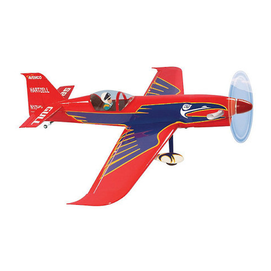
Specifications:
Wing span -------------------------59.8in (152cm).
Wing area --------------592.1sq.in (38.2sq dm).
Weight --------------------6.4 -7.1lbs (2.9-3.2kg).
Length ------------------------------51.2in (130cm).
Engine -------------.46 - .55 cu.in -----2-stroke.
.52 - .72cu.in -----4-stroke.
Radio ----------------- 4 channels with 5 servos.
Advertisement
Table of Contents

Related Manuals for Seagull Models Turbo Raven


Summary of Contents for Seagull Models Turbo Raven
- Page 1 MS: 117 ASSEMBLY MANUAL “Graphics and specifications may change without notice”. Specifications: Wing span -------------------------59.8in (152cm). Wing area --------------592.1sq.in (38.2sq dm). Weight --------------------6.4 -7.1lbs (2.9-3.2kg). Length ------------------------------51.2in (130cm). Engine -------------.46 - .55 cu.in -----2-stroke. .52 - .72cu.in -----4-stroke. Radio ----------------- 4 channels with 5 servos.
-
Page 2: Kit Contents
You will find that most of the work has been done for you already. The motor mount has been fitted and the hinges are pre-installed . Flying the TURBO RAVEN is simply a joy. This instruction manual is designed to help you build a great flying aeroplane. Please read this manual thoroughly before starting assembly of your TURBO RAVEN. -
Page 3: Hinging The Ailerons
www.seagullmodels.com KIT CONTENTS HINGING THE AILERONS. Note: The control surfaces, including the Fuselage ailerons, elevators, and rudder, are Canopy prehinged with hinges installed, but the Left wing panel hinges are not glued in place. It is Right wing panel imperative that you properly adhere the Tail set hinges in place per the steps that follow Aluminum wing tube... -
Page 4: Instruction Manual
Instruction Manual TURBO RAVEN. 4)Deflect the aileron and completely saturate each hinge with thin C/A glue. The ailerons front surface should lightly contact the wing during this procedure. Ideally, when the hinges are glued in place, a 1/64” gap or less will be maintained throughout the lengh of the aileron to the wing panel hinge line. -
Page 5: Hinging The Elevator
www.seagullmodels.com Place epoxy into hole. This will harden the HINGING THE ELEVATOR. threads and prevent the crews from pulling Glue the elevator hinges in place using the loose. same techniques used to hinge the ailerons. Thread a control horn end with aluminum washer, lock nut until the top edge of the end is 18mm from the vase of the horn as shown. - Page 6 Instruction Manual TURBO RAVEN. INSTALL RUDDER CONTROL HORN. 2 sets. Repeat steps to install the rudder control horn as same as steps done for ailerons. 2 sets. 3x40mm. 3x45mm. CONTROL HORN M3 Aluminum Washer Epoxy Horizontal Elevator. Stabilizer. CONTROL HORN...
-
Page 7: Engine Mount Installation
www.seagullmodels.com INSTALLING THE STOPPER ASSEMBLY. 1) Using a modeling knife, carefully cut off the rear portion of one of the 3 nylon tubes leaving 1/2” protruding from the rear of the stopper. This will be the fuel pick up tube. 2) Using a modeling knife, cut one length of silicon fuel line. -
Page 8: Fuel Tank Installation
Instruction Manual TURBO RAVEN. Carefully use a lighter or heat gun to 7) Slide the fuel tank into the fuselage. Guide the lines from the tank through the hole permenently set the angle of the vent tube. in the firewall. - Page 9 www.seagullmodels.com 4) Slide the collar to the axle and setscrew WHEEL AND WHEEL PANTS the collars to secure the collar to the axle and INSTALLATION. then slider the wheel on the axle with a drop of 1) Locate the items neccessary to install oil on the axle so the wheel will spin freely when the wheel and wheel pants as shown.
- Page 10 Instruction Manual TURBO RAVEN. Repeat steps as above to attach remain- Landing Gear. ing wheel pants to the landing gear. wheel Pant. INSTALLING THE MAIN LANDING GEAR TO FUSELAGE. C/A glue. 8) The blind nuts for securing the landing gear are already mounted inside the fuselage.
-
Page 11: Mounting The Engine
www.seagullmodels.com Rudder servo . Switch. Elevator servo . THROTTLE SERVO ARM INSTALLATION. Install adjustable servo connector in the servo arm as same as picture below: MOUNTING THE ENGINE. 1) Position the engine with the drive washer Loctite secure. (115mm) forward of the firewall as shown. Adjustable Servo connector. - Page 12 Instruction Manual TURBO RAVEN. Pushrod wire. 2mm diameter. 8) Reinstall the servo horn by sliding the connector over the pushrod wire. Center the throttle stick and trim and install the servo horn perpendicular to the servo center line. 4) On the fire wall has the location for the throttle pusshrod tube (pre-drill).
-
Page 13: Cowling Installation
www.seagullmodels.com 2) While keeping the back edge of the COWLING INSTALLATION. cowl flush with the marks, align the front of 1) Slide the fiberglass cowl over the the cowl with the crankshaft of the engine. The engine and line up the back edge of the cowl front of the cowl should be positioned so the with the marks you made on the fuselage then crankshaft is in nearly the middle of the cowl... - Page 14 Instruction Manual TURBO RAVEN. ELECTRIC POWER CONVERSION. Epoxy. 1) Locate the items neccessary to install the electric power conversion included with your model. Balsa stick. - Model size: .35-.45 size models - Motor: 35mm 830 rev per volt - Propeller: 10x7 - ESC: 50A Epoxy.
- Page 15 www.seagullmodels.com 4) Locate the plywood battery tray to the Electric motor. Epoxy. fuselage. Tighten the screws using machine screws M3x15mm to secure the tray in position. Battery. 115mm. Epoxy. M3x15mm. 5.2mm. Blind nut. 5) Attach the speed control to the side of the motor box using two-sided tape and tie wraps.
-
Page 16: Spinner Installation
Instruction Manual TURBO RAVEN. SPINNER INSTALLATION. Install the spinner backplate, propeller and spinner cone. Small weight. String. 2) Place the servo between the mounting blocks and space it from the hatch. Use a pencil to mark the mounting hole locations on the blocks. - Page 17 www.seagullmodels.com 6) Secure the servo to the aileron hatch using Phillips screwdriver and the screws provided with the servo. 7) Apply 1-2 drops of thin C/A to each of the mounting tabs. Allow the C/A to cure without using accelerator. 8) A string has been provided in the wing to pull the aileron lead through to the wing root.
- Page 18 Instruction Manual TURBO RAVEN. 8mm. cut. 9) Set the aileron hatch in place and use a 2) Make a 90-degree bend at the mark and cut Phillips screw driver to install it with four wood off the excess wire leaving 8mm past the bend.
-
Page 19: Installing The Horizontal Stabilizer
www.seagullmodels.com Repeat the procedure for the other aileron servo. INSTALLING THE HORIZONTAL STABILIZER. 4) Install the stabilizer onto the fuselage. 1) Using a ruler and a pen, locate the Align the centerline drawn on the top and the centerline of the horizontal stabilizer, at the trail- rear of the stabilizer with the centre of the fu- ing edge, and place a mark. -
Page 20: Installing The Vertical Stabilizer
Instruction Manual TURBO RAVEN. 8) Using a modeling knife, carefully re- move the covering that overlaps the stabilizer mounting platform sides in the fuselage. Re- move the covering from both the top and the bottom of the platform sides. 9) When you are sure that everything is aligned correctly, mix up a generous amount of 30 Minute Epoxy. - Page 21 www.seagullmodels.com C/A glue. Hinge. Remove covering. Epoxy. 1) Put the vertical stabilizer into the in the top of the horizontal fin. The bottom edge of the stabilizer should also be firmly pushed against the top of the horizontal stabilizer. ELEVATOR - RUDDER PUSHROD HORN INSTALLATION.
- Page 22 Instruction Manual TURBO RAVEN. Elevator control horn. Rudder control horn. 3) Thread one clevis and M2 lock nut on to each elevator control rod. Thread the horns on until they are flush with the ends of the con- trol rods.
- Page 23 www.seagullmodels.com 5) With both the rudder servo and rudder 6) Enlarge the outer hole in the rudder servo centered, mark the rudder pushrod at the hole arm using a drill bit. Bend the pushrod wire at it crosses in the rudder servo arm using a felt- the mark made in the last step.
- Page 24 Instruction Manual TURBO RAVEN. 8) Install servos arm to servos. Notice the position of the servo arms on the servos. See picture below. Elevator. Rudder. M3 x 12mm. MOUNTING THE TAIL WHEEL. See pictures below. M3 x 12mm. INSTALLTION PILOT.
-
Page 25: Apply The Decals
www.seagullmodels.com 4) Install the canopy and secure it with M2x6mm screws. C/A glue. 45mm. M2 x 6mm. Remove covering APPLY THE DECALS. and glue bond. 1) If all the decals are precut and ready to stick. Please be certain the model is clean and free from oily fingerprints and dust. - Page 26 Instruction Manual TURBO RAVEN. 4) Open the battery hatch on the fuse- lage to install the battery and close the top hatch in place with nylon bolt. C/A glue. Battery. 3) Slide the wing tube to the fuselage. Attach the aluminium tube into fuselage.
-
Page 27: Control Throws
www.seagullmodels.com Accurately mark the balance point on the top of the wing on both sides of the fuselage. The balance point is located 145 mm back from the leading edge of the wing at the wing root. This is the balance point at which your model should balance for your first flights. -
Page 28: Flight Preparation
Plug in your radio system per the 2) Check every bolt and every glue joint manufacturer's instructions and turn every- in the TURBO RAVEN to ensure that every- thing on. thing is tight and well bonded. C) Check the elevator first. Pull back on 3) Double check the balance of the air- the elevator stick.
Need help?
Do you have a question about the Turbo Raven and is the answer not in the manual?
Questions and answers