Siemens SINUMERIK 840D sl Operating Manual
Sinumerik 840d sl universal
Hide thumbs
Also See for SINUMERIK 840D sl:
- Function manual (2184 pages) ,
- Programming manual (1334 pages) ,
- Commissioning manual (1102 pages)
Table of Contents
Advertisement
Quick Links
Universal
SINUMERIK
SINUMERIK 840D sl
Universal
Operating Manual
Valid for:
SINUMERIK 840D sl/ 840DE sl
CNC software
SINUMERIK Operate for PCU/PC
03/2010
6FC5398-6AP10-4BA0
_ __________________
Foreword
0 H
_ __________________
Introduction
1 H
_ __________________
Setting up the machine
2 H
_ __________________
Working in manual mode
3 H
_ __________________
Machine the workpiece
4 H
_ __________________
Simulating machining
5 H
_ __________________
Multi-channel view
6 H
_ __________________
User data
7 H
_ __________________
Teaching in a program
8 H
_ __________________
Tool management
9 H
_ __________________
Program management
1 0 H
_ __________________
Setting up drives
1 1 H
_ __________________
HT 8
1 2 H
_ __________________
Alarm, error, and system
messages
1 3 H
_ __________________
Appendix
1 4 H
Version
2.6 SP1
2.6 SP1
1
2
3
4
5
6
7
8
9
10
11
12
13
A
Advertisement
Table of Contents

Related Manuals for Siemens SINUMERIK 840D sl


Summary of Contents for Siemens SINUMERIK 840D sl
- Page 1 HT 8 1 2 H _ __________________ Alarm, error, and system messages 1 3 H Valid for: _ __________________ Appendix SINUMERIK 840D sl/ 840DE sl 1 4 H Version CNC software 2.6 SP1 SINUMERIK Operate for PCU/PC 2.6 SP1 03/2010 6FC5398-6AP10-4BA0...
- Page 2 Note the following: WARNING Siemens products may only be used for the applications described in the catalog and in the relevant technical documentation. If products and components from other manufacturers are used, these must be recommended or approved by Siemens. Proper transport, storage, installation, assembly, commissioning, operation and maintenance are required to ensure that the products operate safely and without any problems.
-
Page 3: Foreword
● Researching documentation online Information on DOConCD and direct access to the publications in DOConWEB. ● Compiling individual documentation on the basis of Siemens contents with the My Documentation Manager (MDM), refer to http://www.siemens.com/mdm. My Documentation Manager provides you with a range of features for generating your own machine documentation. - Page 4 Europe / Africa Phone +49 180 5050 222 +49 180 5050 223 0.14 €/min. from German landlines, max. 0.42 €/min for calls from a mobile phone Internet http://www.siemens.com/automation/support-request Americas Phone +1 423 262 2522 +1 423 262 2200 E-mail mailto:techsupport.sea@siemens.com...
- Page 5 Questions about the manual If you have any queries (suggestions, corrections) in relation to this documentation, please fax or e-mail us: +49 9131- 98 2176 E-mail mailto:docu.motioncontrol@siemens.com A fax form is available in the appendix of this document. SINUMERIK Internet address http://www.siemens.com/sinumerik Universal...
- Page 6 Foreword Universal Operating Manual, 03/2010, 6FC5398-6AP10-4BA0...
- Page 7 Table of contents Foreword ..............................3 Introduction.............................. 13 Product overview .........................13 Operator panel fronts ........................14 1.2.1 Overview ............................14 1.2.2 Keys of the operator panel......................16 Machine control panels ........................22 1.3.1 Overview ............................22 1.3.2 Controls on the machine control panel ..................22 Operator interface ........................25 1.4.1 Screen layout ..........................25 1.4.2...
- Page 8 Table of contents 2.5.6 Deleting a work offset........................65 Monitoring axis and spindle data ....................66 2.6.1 Specify working area limitations....................66 2.6.2 Editing spindle data........................67 Displaying setting data lists......................68 Handwheel assignment....................... 68 MDA ............................70 2.9.1 Loading an MDA program from the Program Manager .............. 70 2.9.2 Saving an MDA program......................
- Page 9 Table of contents 4.10 Editing a program........................103 4.10.1 Searching in programs.......................103 4.10.2 Replacing program text......................105 4.10.3 Copying/pasting/deleting program blocks..................106 4.10.4 Renumbering a program ......................107 4.10.5 Opening a second program .......................107 4.10.6 Editor settings ..........................109 4.11 Display G and auxiliary functions....................110 4.11.1 Selected G functions........................110 4.11.2...
- Page 10 Table of contents Channel GUD..........................150 Local LUD..........................152 Program PUD..........................153 Searching for user data......................154 Defining and activating user data....................155 Teaching in a program........................... 157 Overview ........................... 157 General sequence........................157 Inserting a block ........................158 8.3.1 Input parameters for teach-in blocks..................
- Page 11 Table of contents 9.12 Displaying tool details ........................200 9.13 Changing a tool type ........................201 Program management ........................... 203 10.1 Overview ............................203 10.1.1 NC memory ..........................206 10.1.2 Local drive..........................206 10.1.3 USB drives ..........................207 10.2 Opening and closing a program....................208 10.3 Executing a program........................209 10.4 Creating a directory/program/joblist/program list ...............211 10.4.1...
- Page 12 Table of contents 13.1 Displaying alarms........................253 13.2 Displaying an alarm log......................255 13.3 Displaying messages ........................ 255 13.4 PLC and NC variables....................... 256 Displaying and editing PLC and NC variables ................256 13.4.1 13.4.2 Saving and loading screen forms....................260 13.4.3 Loading PLC symbols .......................
-
Page 13: Product Overview
Introduction Product overview The SINUMERIK controller is a CNC (Computerized Numerical Controller) for machine tools. You can use the CNC to implement the following basic functions in conjunction with a machine tool: ● Creation and adaptation of part programs ● Execution of part programs ●... -
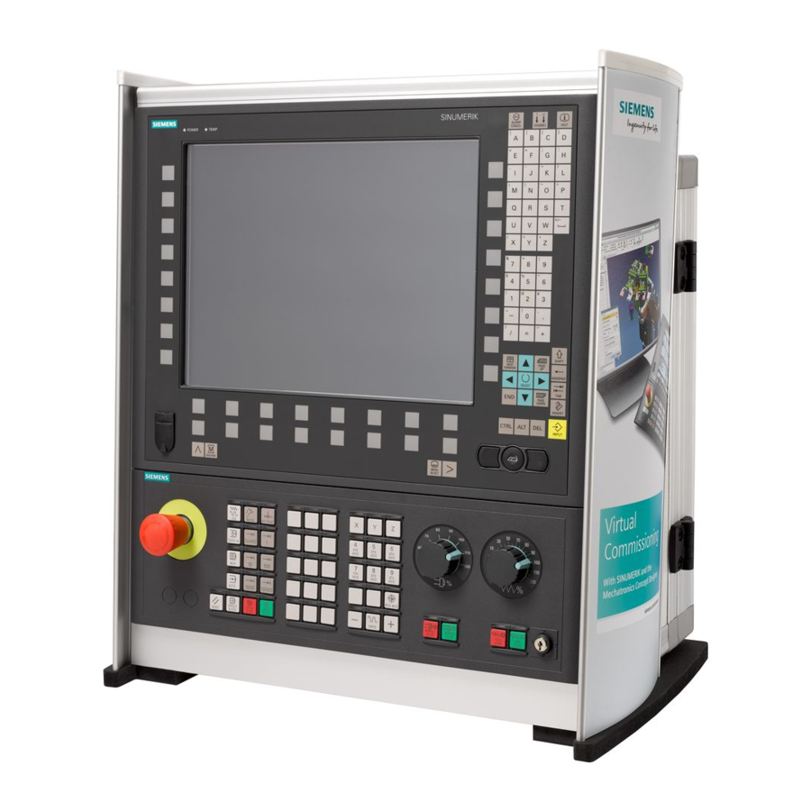
Page 14: Operator Panel Fronts
Introduction 1.2 Operator panel fronts Operator panel fronts 1.2.1 Overview Introduction The display (screen) and operation (e.g. hardkeys and softkeys) of the SINUMERIK Operate user interface use the operator panel front. In this example, the OP 010 operator panel front is used to illustrate the components that are available for operating the controller and machine tool. - Page 15 A more precise description as well as a view of the other operator panel fronts that can be used may be found in the following reference: Operator Components and Networking Manual; SINUMERIK 840D sl/840Di sl Universal Operating Manual, 03/2010, 6FC5398-6AP10-4BA0...
-
Page 16: Keys Of The Operator Panel
Introduction 1.2 Operator panel fronts 1.2.2 Keys of the operator panel The following keys and key combinations are available for operation of the control and the machine tool. Keys and key combinations Function <ALARM CANCEL> Cancels alarms and messages that are marked with this symbol. - Page 17 Introduction 1.2 Operator panel fronts Function <PAGE DOWN> + <CTRL> Positions the cursor to the lowest line of a window. <Cursor right> • Editing box Opens a directory or program (e.g. cycle) in the editor. • Navigation Moves the cursor further to the right by one character. <Cursor right>...
- Page 18 Introduction 1.2 Operator panel fronts Function <Cursor up> + <SHIFT> In the program manager and in the program editor, selects a contiguous selection of directories and program blocks. <Cursor down> • Editing box Moves the cursor downwards. • Navigation – Moves the cursor in a table to the next cell downwards. –...
- Page 19 Introduction 1.2 Operator panel fronts Function <BACKSPACE> • Editing box Deletes a character selected to the left of the cursor. • Navigation Deletes all of the selected characters to the left of the cursor. <BACKSPACE> + <CTRL> Deletes a word selected to the left of the cursor. <TAB>...
- Page 20 Introduction 1.2 Operator panel fronts Function <CTRL> + <V> Inserts text from the clipboard: • Pastes the text from the clipboard at the actual cursor position. • Pastes text from the clipboard at the position of a selected text. <CTRL> + <ALT> + <C> Creates a complete archive on an external data carrier (USB- FlashDrive).
- Page 21 Introduction 1.2 Operator panel fronts Function <INPUT> • Completes input of a value in the entry field. • Opens a director or a program. <ALARM> - only OP 010 and OP 010C Select the "Diagnosis" operating area. <PROGRAM> - only OP 010 and OP 010C Calls the "Program Manager"...
-
Page 22: Machine Control Panels
1.3.1 Overview The machine tool can be equipped with a machine control panel by Siemens or with a specific machine control panel from the machine manufacturer. You use the machine control panel to initiate actions on the machine tool such as traversing an axis or starting the machining of a workpiece. - Page 23 Introduction 1.3 Machine control panels Machine manufacturer For additional responses to pressing the Emergency Stop button, please refer to the machine manufacturer's instructions. Installation locations for control devices (d = 16 mm) RESET Stop processing the current programs. • The NCK control remains synchronized with the machine. It is in its initial state and ready for a new program run.
- Page 24 Introduction 1.3 Machine control panels Machine manufacturer A machine data code defines how the increment value is interpreted. Customer keys T1 to T15 Traversal axes with rapid traverse superposition and coordinate exchange Axis keys Selects an axis. Direction keys Select the traversing direction. <RAPID>...
-
Page 25: Operator Interface
Introduction 1.4 Operator interface Operator interface 1.4.1 Screen layout Overview Active operating area and mode Alarm/message line Program name Channel state and program control Channel operational messages Axis position display in actual value window Universal Operating Manual, 03/2010, 6FC5398-6AP10-4BA0... -
Page 26: Status Display
Introduction 1.4 Operator interface Display for active tool T • current feedrate F • active spindle with current status (S) • Spindle utilization rate in percent • Operating window with program block display Display of active G functions, all G functions, auxiliary functions and input window for different functions (for example, skip blocks, program control). - Page 27 Introduction 1.4 Operator interface Display Description "Diagnosis" operating area "Start-up" operating area Active mode or submode "Jog" mode "MDA" mode "Auto" mode "Teach In" submode "Repos" submode "Ref Point" submode Alarms and messages Alarm display The alarm numbers are displayed in white lettering on a red background.
- Page 28 Introduction 1.4 Operator interface Second line Display Description Program path and program name The displays in the second line can be configured. Machine manufacturer Please also refer to the machine manufacturer's instructions. Third line Display Description Display of channel status. If several channels are present on the machine, the channel name is also displayed.
-
Page 29: Actual Value Window
Introduction 1.4 Operator interface See also Channel switchover (Page 53) Touch operation (Page 38) 1.4.3 Actual value window The actual values of the axes and their positions are displayed. Work/Machine The displayed coordinates are based on either the machine coordinate system or the workpiece coordinate system. -
Page 30: T,F,S Window
Introduction 1.4 Operator interface Display Meaning Display of distance-to-go The distance-to-go for the current NC block is displayed while the program is running. Feed/override The feed acting on the axes, as well as the override, are displayed in the full-screen version. Repos offset The distances traversed in manual mode are displayed. - Page 31 Introduction 1.4 Operator interface Feed data Display Meaning Feed disable Actual feed value If several axes traverse, is displayed for: "JOG" mode: Axis feed for the traversing axis • "MDA" and "AUTO" mode: Programmed axis feed • Rapid traverse G0 is active 0.000 No feed is active Override...
-
Page 32: Current Block Display
Introduction 1.4 Operator interface 1.4.5 Current block display The window of the current block display shows you the program blocks currently being executed. Display of current program The following information is displayed in the running program: ● The workpiece name or program name is entered in the title row. ●... - Page 33 Introduction 1.4 Operator interface Changing the operating area Press the <MENU SELECT> key and select the desired operating area using the horizontal softkey bar. You can call the "Machine" operating area directly using the key on the operator panel. Press the <MACHINE> key to select the "machine" operating area. Changing the operating mode You can select a mode or submode directly using the keys on the machine control panel or using the vertical softkeys in the main menu.
-
Page 34: Entering Or Selecting Parameters
Introduction 1.4 Operator interface See also Controls on the machine control panel (Page 22) Channel switchover (Page 53) 1.4.7 Entering or selecting parameters When setting up the machine and during programming, you must enter various parameter values in the entry fields. The background color of the fields provides information on the status of the input field. - Page 35 Introduction 1.4 Operator interface If required, enter a value in the associated input field. Press the <INPUT> key to complete the parameter input. Changing or calculating parameters If you only want to change individual characters in an input field rather than overwriting the entire entry, switch to insertion mode.
-
Page 36: Pocket Calculator
Introduction 1.4 Operator interface Enter "r" or "R" as well as the number x from which you would like to <number> extract the root. Enter "s" or "S" as well as the number x for which you would like to <number>... - Page 37 Introduction 1.4 Operator interface Procedure Position the cursor on the desired input field. Press the <=>. The pocket calculator is displayed. Input the arithmetic statement. You can use arithmetic symbols, numbers, and commas. Press the equals symbol on the calculator. - OR - Press the "Calculate"...
-
Page 38: Context Menu
Introduction 1.4 Operator interface See also Entering or selecting parameters (Page 34) 1.4.9 Context menu When you right-click, the context menu opens and provides the following functions: ● Cut Cut Ctrl+X ● Copy Copy Ctrl+C ● Paste Paste Ctrl+V Program editor Additional functions are available in the editor ●... -
Page 39: Changing The User Interface Language
Introduction 1.4 Operator interface 1.4.11 Changing the user interface language Procedure Select the "Startup" operating area. Press the "Change language" softkey. The "Language selection" window opens. The language set last is selected. Position the cursor on the desired language. Press the "OK" softkey. - OR - Press the <INPUT>... -
Page 40: Entering Asian Characters
Introduction 1.4 Operator interface 1.4.12 Entering Asian characters You have the possibility of entering Asian characters. Note Call the input editor with <Alt + S> The input editor can only be called there where it is permissible to enter Asian characters. You can select a character by using the Pinyin phonetic notation, which enables Chinese characters to be expressed by combining Latin letters. - Page 41 Introduction 1.4 Operator interface Procedure Editing characters Open the screen form and position the cursor on the entry field and press the <Alt +S> keys. The editor is displayed. Enter the desired phonetic notation. Click the <Cursor down> key to access the dictionary. By keeping the <Cursor down>...
-
Page 42: Protection Levels
● Work offsets ● Setting data ● Program creation / program editing References For additional information, please refer to the following documentation: Commissioning Manual SINUMERIK Operate (IM9) / SINUMERIK 840D sl Softkeys Machine operating area Protection level End user (protection level 3) - Page 43 Introduction 1.4 Operator interface Diagnostics operating area Protection level Manufacturer (protection level 1) End user (protection level 3) Service (protection level 2) Startup operating area Protection levels End user (protection level 3) Keyswitch 3 (protection level 4) Keyswitch 3 (protection level 4) Key switch 3 (protection level 4) Keyswitch 3...
-
Page 44: Online Help In Sinumerik Operate
Introduction 1.4 Operator interface 1.4.14 Online help in SINUMERIK Operate A comprehensive context-sensitive online help is stored in the control system. ● A brief description is provided for each window and, if required, step-by-step instructions for the operating sequences. ● A detailed help is provided in the editor for every entered G code. You can also display all G functions and take over a selected command directly from the help into the editor. - Page 45 Introduction 1.4 Operator interface Calling a topic in the table of contents Press the "Table of contents" softkey. Depending on which technology you are using, the Operating Manuals "Operator control Milling", "Operator control Turning" or "Operator control Universal" as well as the "Programming" Programming Manual are displayed.
- Page 46 Introduction 1.4 Operator interface Displaying alarm descriptions and machine data If messages or alarms are pending in the "Alarms", "Messages" or "Alarm Log" window, position the cursor at the appropriate display and press the <HELP> or the <F12> key. The associated alarm description is displayed. If you are in the "Startup"...
-
Page 47: Switching On And Switching Off
Setting up the machine Switching on and switching off Start-up When the control starts up, the main screen opens according to the operating mode specified by the machine manufacturer. In general, this is the main screen for the "REF POINT" submode. Machine manufacturer Please also refer to the machine manufacturer's instructions. -
Page 48: Approaching A Reference Point
Setting up the machine 2.2 Approaching a reference point Approaching a reference point 2.2.1 Referencing axes Your machine tool can be equipped with an absolute or incremental path measuring system. An axis with incremental path measuring system must be referenced after the control has been switched-on –... -
Page 49: User Agreement
Setting up the machine 2.2 Approaching a reference point Select the axis to be traversed. Press the <-> or <+> key. The selected axis moves to the reference point. If you have pressed the wrong direction key, the action is not accepted and the axes do not move. - Page 50 Setting up the machine 2.2 Approaching a reference point Procedure Select the "Machine" operating area. Press the <REF POINT> key. Select the axis to be traversed. Press the <-> or <+> key. The selected axis moves to the reference point and stops. The coordinate of the reference point is displayed.
-
Page 51: Modes Of Operation
Setting up the machine 2.3 Modes of operation Modes of operation 2.3.1 General information You can work in three different operating modes. "JOG" mode "JOG" mode is used for the following preparatory actions: ● Approach reference point, i.e. the machine axis is referenced ●... - Page 52 Setting up the machine 2.3 Modes of operation "REPOS" submode The "REPOS" submode is used for repositioning to a defined position. After a program interruption (e.g. to correct tool wear values) move the tool away from the contour in "JOG" mode.
-
Page 53: Modes Groups And Channels
Setting up the machine 2.3 Modes of operation 2.3.2 Modes groups and channels Every channel behaves like an independent NC. A maximum of one part program can be processed per channel. ● Control with 1channel One mode group exists. ● Control with several channels Channels can be grouped to form several "mode groups."... - Page 54 Another channel can be selected by pressing one of the other softkeys. References Commissioning Manual SINUMERIK Operate (IM9) / SINUMERIK 840D sl Channel switchover via touch operation On the HT 8 and when using a touch screen operating panel, you can switch to the next channel via touch operation in the status display.
-
Page 55: Settings For The Machine
Setting up the machine 2.4 Settings for the machine Settings for the machine 2.4.1 Switching over the coordinate system (MCS/WCS) The coordinates in the actual value display are relative to either the machine coordinate system or the workpiece coordinate system. By default, the workpiece coordinate system is set as a reference for the actual value display. - Page 56 Setting up the machine 2.4 Settings for the machine Proceed as follows Select <JOG> or <AUTO> mode in the "Machine" operating area. Press the menu forward key and the "Settings" softkey. A new vertical softkey bar appears. Press the "Switch to inch" softkey. A prompt asks you whether you really want to switch over the unit of measurement.
-
Page 57: Setting The Work Offset
Setting up the machine 2.4 Settings for the machine 2.4.3 Setting the work offset You can enter a new position value in the actual value display for individual axes when a settable work offset is active. The difference between the position value in the machine coordinate system MCS and the new position value in the workpiece coordinate system WCS is saved permanently in the currently active work offset (e.g. - Page 58 Setting up the machine 2.4 Settings for the machine Resetting the actual value Press the "Delete active WO" softkey. The offset is deleted permanently. NOTICE Irreversible active work offset The current active work offset is irreversibly deleted by this action. Relative actual value Press the "REL actual values"...
-
Page 59: Work Offsets
Setting up the machine 2.5 Work offsets Work offsets Following reference point approach, the actual value display for the axis coordinates is based on the machine zero (M) of the machine coordinate system (Machine). The program for machining the workpiece, however, is based on the workpiece zero (W) of the workpiece coordinate system (Work). -
Page 60: Display Active Zero Offset
Setting up the machine 2.5 Work offsets Coarse and fine offsets Every work offset (G54 to G57, G505 to G599) consists of a coarse offset and a fine offset. You can call the work offsets from any program (coarse and fine offsets are added together). You can save the workpiece zero, for example, in the coarse offset, and then store the offset that occurs when a new workpiece is clamped between the old and the new workpiece zero in the fine offset. -
Page 61: Displaying The Work Offset "Overview
Setting up the machine 2.5 Work offsets Procedure Select the "Parameter" operating area. Press the "Work offset" softkey. The "Work Offset - Active" window is opened. Note Further details on work offsets If you would like to see further details about the specified offsets or if you would like to change values for the rotation, scaling or mirroring, press the "Details"... -
Page 62: Displaying And Editing Base Zero Offset
Setting up the machine 2.5 Work offsets Work offsets Cycle reference Displays the additional work offsets programmed with $P_CYCFRAME. Total WO Displays the active work offset, resulting from the total of all work offsets. Procedure Select the "Parameter" operating area. Press the "Work offset"... -
Page 63: Displaying And Editing Settable Zero Offset
Setting up the machine 2.5 Work offsets Note Activate base offsets The offsets specified here are immediately active. 2.5.4 Displaying and editing settable zero offset All settable offsets, divided into coarse and fine offsets, are displayed in the "Work Offset - G54..G599"... -
Page 64: Displaying The Zero Offset Details
Setting up the machine 2.5 Work offsets 2.5.5 Displaying the zero offset details. For each work offset, you can display and edit all data for all axes. You can also delete work offsets. For every axis, values for the following data will be displayed: ●... -
Page 65: Deleting A Work Offset
Setting up the machine 2.5 Work offsets Press the "WO +" or "WO -" softkey to select the next or previous offset, respectively, within the selected area ("Active", "Base", "G54 to G599") without first having to switch to the overview window. If you have reached the end of the range (e.g. -
Page 66: Monitoring Axis And Spindle Data
Setting up the machine 2.6 Monitoring axis and spindle data Monitoring axis and spindle data 2.6.1 Specify working area limitations The "Working area limitation" function can be used to limit the range within which a tool can traverse in all channel axes. These commands allow you to set up protection zones in the working area which are out of bounds for tool movements. -
Page 67: Editing Spindle Data
Setting up the machine 2.6 Monitoring axis and spindle data 2.6.2 Editing spindle data The speed limits set for the spindles that must not be under- or overshot are displayed in the "Spindles" window. You can limit the spindle speeds in fields "Minimum" and "Maximum" within the limit values defined in the relevant machine data. -
Page 68: Displaying Setting Data Lists
Setting up the machine 2.7 Displaying setting data lists Displaying setting data lists You can display lists with configured setting data. Machine manufacturer Please refer to the machine manufacturer's specifications. Procedure Select the "Parameter" operating area. Press "Setting data" and "Data lists" softkeys. The "Setting data list"... - Page 69 Setting up the machine 2.8 Handwheel assignment Machine manufacturer Please refer to the machine manufacturer's specifications. Procedure Select the "Machine" operating area. Press the <JOG>, <AUTO> or <MDA> key. Press the menu forward key and the "Handwheel" softkey. The "Handwheel" window appears. A field for axis assignment will be offered for every connected handwheel.
-
Page 70: Loading An Mda Program From The Program Manager
Setting up the machine 2.9 MDA Deactivate handwheel Position the cursor on the handwheel whose assignment you wish to cancel (e.g. No. 1). Press the softkey for the assigned axis again (e.g. "X"). - OR - Open the "Axis" selection box using the <INSERT> key, navigate to the empty field, and press the <INPUT>... -
Page 71: Saving An Mda Program
Setting up the machine 2.9 MDA A changeover is made into the Program Manager. The "Load in MDA" window opens. The program manager is displayed in it. Select the program that you would like to edit or execute in the MDA window. -
Page 72: Executing An Mda Program
Setting up the machine 2.9 MDA 2.9.3 Executing an MDA program Proceed as follows Select the "Machine" operating area. Press the <MDA> key. The MDA editor opens. Input the desired G-code commands using the operator’s keyboard. Press the <CYCLE START> key. The control executes the input blocks. -
Page 73: Deleting An Mda Program
Setting up the machine 2.9 MDA 2.9.4 Deleting an MDA program Precondition The MDA editor contains a program that you created in the MDI window or loaded from the program manager. Procedure Press the "Delete blocks" softkey. The program displayed in the program window is deleted. Universal Operating Manual, 03/2010, 6FC5398-6AP10-4BA0... - Page 74 Setting up the machine 2.9 MDA Universal Operating Manual, 03/2010, 6FC5398-6AP10-4BA0...
-
Page 75: General
Working in manual mode General Always use "JOG" mode when you want to set up the machine for the execution of a program or to carry out simple traversing movements on the machine: ● Synchronize the measuring system of the controller with the machine (reference point approach) ●... - Page 76 Working in manual mode 3.2 Selecting a tool and spindle Display Meaning Input of the tool (name or location number) You can select a tool from the tool list using the "Select tool" softkey. Cutting edge number of the tool (1 - 9) Spindle Spindle selection, identification with spindle number Spindle M function...
-
Page 77: Selecting A Tool
Working in manual mode 3.2 Selecting a tool and spindle 3.2.2 Selecting a tool Procedure Select the "JOG" operating mode. Press the "T, S, M" softkey. Enter the name or the number of the tool T in the input field. - OR - Press the "Select tool"... -
Page 78: Position Spindle
Working in manual mode 3.2 Selecting a tool and spindle Select the desired spindle (e.g. S1) and enter the desired spindle speed (rpm) in the adjacent input field. The spindle remains stationary. If the machine has a gearbox for the spindle, set the gear stage (e.g. auto). -
Page 79: Traversing Axes
Working in manual mode 3.3 Traversing axes Enter the desired spindle stop position. The spindle position is specified in degrees. Press the <CYCLE START> key. The spindle is moved to the desired position. Note You can use this function to position the spindle at a specific angle, e.g. during a tool change. -
Page 80: Traversing Axes By A Variable Increment
Working in manual mode 3.3 Traversing axes Press keys 1, 10, etc. up to 10000 in order to move the axis in a defined increment. The numbers on the keys indicate the traverse path in micrometers or micro-inches. Example: Press the "100" button for a desired increment of 100 μm (= 0.1 mm). -
Page 81: Positioning Axes
Working in manual mode 3.4 Positioning axes Enter the desired value for the "Variable increment" parameter. Example: Enter 500 for a desired increment of 500 μm (0.5 mm). Press the <Inc VAR> key. Select the axis to be traversed. Press the <+> or <-> key. Each time you press the key the selected axis is traversed by the set increment. -
Page 82: Default Settings For Manual Mode
Working in manual mode 3.5 Default settings for manual mode Default settings for manual mode Specify the configurations for manual mode in the "Settings for manual operation" window. Presettings Settings Description Type of feedrate Here, you select the type of feedrate. G94: Axis feedrate/linear feedrate •... -
Page 83: Starting And Stopping Machining
Machine the workpiece Starting and stopping machining During execution of a program, the workpiece is machined in accordance with the programming on the machine. After the program is started in automatic mode, workpiece machining is performed automatically. Requirements The following requirements must be met before executing a program: ●... -
Page 84: Selecting A Program
Machine the workpiece 4.2 Selecting a program Stopping machining Press the <CYCLE STOP> key. Machining stops immediately. Individual program blocks are not executed to the end. On the next start, machining is resumed from the point where it left off. Canceling machining Press the <RESET>... -
Page 85: Program Running-In
Machine the workpiece 4.3 Program running-in Place the cursor on the desired program. Press the "Select" softkey. The program is selected. When the program has been successfully selected, an automatic changeover to the "Machine" operating area occurs. Program running-in When testing a program, the system can interrupt the machining of the workpiece after each program block, which triggers a movement or auxiliary function on the machine. -
Page 86: Display Current Program Block
Machine the workpiece 4.4 Display current program block Procedure Press the "Prog. ctrl." softkey and select the desired variant in the "SBL" field. Press the <SINGLE BLOCK> key. Press the <CYCLE START> key. Depending on the execution variant, the first block will be executed. Then the machining stops. -
Page 87: Displaying A Basic Block
Machine the workpiece 4.4 Display current program block Editing a program directly In the Reset state, you can edit the current program directly. Press the <INSERT> key. Place the cursor at the relevant position and edit the program block. Direct editing is only possible for G code blocks in the NC memory, not for external execution. -
Page 88: Display Program Level
Machine the workpiece 4.4 Display current program block Press the <CYCLE START> key to start the program execution. The axis positions to be approached, modal G functions, etc., are displayed in the "Basic Blocks" window for the currently active program block. -
Page 89: Correcting A Program
Machine the workpiece 4.5 Correcting a program Correcting a program As soon as a syntax error in the part program is detected by the controller, program execution is interrupted and the syntax error is displayed in the alarm line. Correction possibilities Depending on the state of the control system, you can make the following corrections using the Program editing function. -
Page 90: Repositioning Axes
Machine the workpiece 4.6 Repositioning axes Repositioning axes After a program interruption in automatic mode (e.g. after a tool breaks) you can move the tool away from the contour in manual mode. The coordinates of the interrupt position will be saved. The distances traversed in manual mode are displayed in the actual value window. -
Page 91: Starting Execution At A Specific Point
Machine the workpiece 4.7 Starting execution at a specific point Starting execution at a specific point 4.7.1 Use block search If you would only like to perform a certain section of a program on the machine, then you need not start the program from the beginning. You can also start the program from a specified program block. - Page 92 Machine the workpiece 4.7 Starting execution at a specific point Cascaded search You can start another search from the "Search target found" state. The cascading can be continued any number of times after every search target found. Note Another cascaded block search can be started from the stopped program execution only if the search target has been found.
-
Page 93: Continuing Program From Search Target
Machine the workpiece 4.7 Starting execution at a specific point 4.7.2 Continuing program from search target To continue the program at the desired position, press the <CYCLE START> key twice. ● The first CYCLE START outputs the auxiliary functions collected during the search. The program is then in the Stop state. -
Page 94: Defining An Interruption Point As Search Target
Machine the workpiece 4.7 Starting execution at a specific point 4.7.4 Defining an interruption point as search target Precondition A program was selected in "AUTO" mode and interrupted during execution through CYCLE STOP or RESET. Software option You require the "Extended operator functions" option (only for 828D). Procedure Press the "Block search"... -
Page 95: Entering The Search Target Via Search Pointer
Machine the workpiece 4.7 Starting execution at a specific point 4.7.5 Entering the search target via search pointer Enter the program point which you would like to proceed to in the "Search Pointer" window. Software option You require the "Extended operator functions" option for the "Search pointer" function (only for 828D). -
Page 96: Parameters For Block Search In The Search Pointer
Machine the workpiece 4.7 Starting execution at a specific point Note Interruption point You can load the interruption point in search pointer mode. 4.7.6 Parameters for block search in the search pointer Parameter Meaning Number of program level Program: The name of the main program is automatically entered Ext: File extension Pass counter... - Page 97 The search speed depends on MD settings. Machine manufacturer Please refer to the machine manufacturer's specifications. References For additional information, please refer to the following documentation: Commissioning Manual SINUMERIK Operate (IM9) / SINUMERIK 840D sl Universal Operating Manual, 03/2010, 6FC5398-6AP10-4BA0...
-
Page 98: Controlling The Program Run
Machine the workpiece 4.8 Controlling the program run Procedure Select the "Machine" operating area. Press the <AUTO> key. Press the "Block search" and "Block search mode" softkeys. The "Search Mode" window will open. Controlling the program run 4.8.1 Program control You can change the program sequence in the "AUTO"... - Page 99 Machine the workpiece 4.8 Controlling the program run Abbreviation/program Scope control Programmed stop 2 The processing of the program stops at every block in which the "Cycle end" is programmed (e.g. with M101). (e.g. M101) Note: In order to continue executing the program, press the <CYCLE START> key again. Note: The display can be changed.
-
Page 100: Skip Blocks
Machine the workpiece 4.8 Controlling the program run See also Setting for automatic mode (Page 118) 4.8.2 Skip blocks It is possible to skip program blocks, which are not to be executed every time the program runs. The skip blocks are identified by placing a "/" (forward slash) or "/x (x = number of skip level) character in front of the block number. -
Page 101: Overstore
Machine the workpiece 4.9 Overstore Procedure Select the "Machine" operating area. Press the <AUTO> or <MDA> key. Press the "Prog. ctrl." and "Skip blocks" softkeys. The "Program control" window appears and shows a list of block levels. Overstore With overstore, you have the option of executing technological parameters (for example, auxiliary functions, axis feed, spindle speed, programmable instructions, etc.) before the program is actually started. - Page 102 Machine the workpiece 4.9 Overstore Precondition The program to be corrected is in the Stop or Reset mode. Procedure Open the program in the "AUTO" mode. Press the "Overstore" softkey. The "Overstore" window opens. Enter the required data and NC block. Press the <CYCLE START>...
-
Page 103: Editing A Program
Machine the workpiece 4.10 Editing a program 4.10 Editing a program With the editor, you are able to render, supplement, or change part programs. Note The maximum block length is 512 characters. Calling the editor ● The editor is started via the "Program correction" function in the "Machine" operating area. - Page 104 Machine the workpiece 4.10 Editing a program Procedure Press the "Search" softkey. A new vertical softkey bar appears. The "Search" window opens at the same time. Enter the desired search term in the "Text" field. Select "Whole words" if you want to search for whole words only. Position the cursor in the "Direction"...
-
Page 105: Replacing Program Text
Machine the workpiece 4.10 Editing a program 4.10.2 Replacing program text You can find and replace text in one step. Requirement The desired program is opened in the editor. Proceed as follows Press the "Search" softkey. A new vertical softkey bar appears. Press the "Find + replace"... -
Page 106: Copying/Pasting/Deleting Program Blocks
Machine the workpiece 4.10 Editing a program 4.10.3 Copying/pasting/deleting program blocks Precondition The program is opened in the editor. Procedure Press the "Mark" softkey. - OR - Press the <SELECT> key. Select the desired program blocks with the cursor or mouse. Press the "Copy"... -
Page 107: Renumbering A Program
Machine the workpiece 4.10 Editing a program 4.10.4 Renumbering a program You can modify the block numbering of programs opened in the editor at a later point in time. Requirement The program is opened in the editor. Procedure Press the ">>" softkey. A new vertical softkey bar appears. - Page 108 Machine the workpiece 4.10 Editing a program Note Pasting program blocks Jobshop machining steps cannot be copied into a G code program. Precondition You have opened a program in the Editor. Procedure Press the ">>" and "Open 2nd program" softkeys. The "Select 2nd program"...
-
Page 109: Editor Settings
Machine the workpiece 4.10 Editing a program 4.10.6 Editor settings Enter the default settings in the "Settings" window that are to take effect automatically when the editor is opened. Presettings Settings Meaning Number Yes: A new block number will automatically be assigned after every line automatically change. -
Page 110: Display G And Auxiliary Functions
Machine the workpiece 4.11 Display G and auxiliary functions Press the ">>" and "Settings" softkeys. The "Settings" window appears. Make the desired changes here and press the "OK" softkey to confirm your settings. 4.11 Display G and auxiliary functions 4.11.1 Selected G functions 16 selected G groups are displayed in the "G Function"... - Page 111 Machine the workpiece 4.11 Display G and auxiliary functions Group Meaning G group 29 Radius/diameter programming (e.g. DIAMOF, DIAMCYCOF) G group 30 Compressor ON/OFF (e.g. COMPOF) G groups displayed by default (ISO code) Group Meaning G group 1 Modally active motion commands (e.g. G0, G1, G2, G3) G group 2 Non-modally active motion commands, dwell time (e.g.
-
Page 112: All G Functions
References For more information about configuring the displayed G groups, refer to the following document: Commissioning Manual SINUMERIK Operate (IM9) / SINUMERIK 840D sl 4.11.2 All G functions All G groups and their group numbers are listed in the "G Functions" window. - Page 113 Machine the workpiece 4.11 Display G and auxiliary functions Display Meaning TRAANG Inclined axis transformation active TRACON Cascaded transformation active For TRACON, two transformations (TRAANG and TRACYL or TRAANG and TRANSMIT) are activated in succession. ● Current zero offsets ● Spindle speed ●...
-
Page 114: Auxiliary Functions
Machine the workpiece 4.12 Displaying status of synchronized actions 4.11.3 Auxiliary functions Auxiliary functions include M and H functions preprogrammed by the machine manufacturer, which transfer parameters to the PLC to trigger reactions defined by the manufacturer. Displayed auxiliary functions Up to five current M functions and three H functions are displayed in the "Auxiliary Functions"... - Page 115 Machine the workpiece 4.12 Displaying status of synchronized actions ● Waiting ● Active ● Blocked Non-modal synchronized actions can only be identified by their status display. They are only displayed during execution. Synchronization types Synchronization types Meaning ID=n Modal synchronized actions in the automatic mode up to the end of program, local to program;...
-
Page 116: Displaying The Program Runtime And Counting Workpieces
Machine the workpiece 4.13 Displaying the program runtime and counting workpieces - AND / OR - Press the "IDS" softkey if you wish to hide static synchronized actions. - AND / OR - Press the "Blockwise" softkey if you wish to hide the non-modal synchronized actions in the automatic mode. - Page 117 Machine the workpiece 4.13 Displaying the program runtime and counting workpieces Displayed times ● Program Pressing the softkey the first time shows how long the program has already been running. At every further start of the program, the time required to run the entire program the first time is displayed.
-
Page 118: Setting For Automatic Mode
Machine the workpiece 4.14 Setting for automatic mode Press the "Times, Counter" softkey. The "Times, Counter" window opens. Select "Yes" under "Count workpieces" if you want to count completed workpieces. Enter the number of workpieces needed in the "Desired workpieces" field. - Page 119 Machine the workpiece 4.14 Setting for automatic mode Procedure Select the "Machine" operating area. Press the <AUTO> key. Press the menu forward key and the "Settings" softkey. The "Settings for Automatic Operation" window is opened. In "DRY run feedrate," enter the desired dry run speed. Enter the desired percentage in the "Reduced rapid traverse RG0"...
- Page 120 Machine the workpiece 4.14 Setting for automatic mode Universal Operating Manual, 03/2010, 6FC5398-6AP10-4BA0...
-
Page 121: Overview
Simulating machining Overview During simulation, the current program is calculated in its entirety and the result displayed in graphic form. The result of programming is verified without traversing the machine axes. Incorrectly programmed machining steps are detected at an early stage and incorrect machining on the workpiece prevented. - Page 122 Simulating machining 5.1 Overview In spite of this, unavoidable Machine references are in the programming, such as for example, the tool change point in the Machine, the retraction position when swiveling and the table components of a swivel kinematic. Depending on the actual work offset - in the worst case - these Machine references can mean that collisions are shown in the simulation that would not occur for a realistic work offset - or vice versa, collisions are not shown, which could occur for a realistic work offset.
- Page 123 Simulating machining 5.1 Overview Views The following views are available for all three variants: ● Top view ● 3D view ● Side views Status display The current axis coordinates, the override, the current tool with cutting edge, the current program block, the feedrate and the machining time are displayed. In all views, a clock is displayed during graphical processing.
- Page 124 Simulating machining 5.1 Overview General conditions ● All of the existing data records (Toolcarrier / TRAORI, TRACYL) are evaluated and must be correctly commissioned for correct simulation. ● Transformations with swiveled linear axis (TRAORI 64 - 69) as well as OEM transformations (TRAORI 4096 - 4098) are not supported.
- Page 125 Simulating machining 5.1 Overview Examples Several examples for machine types that are supported: Swivel head 90°/90° Swivel head 90°/45° Universal Operating Manual, 03/2010, 6FC5398-6AP10-4BA0...
- Page 126 Simulating machining 5.1 Overview Swivel table 90°/90° Swivel table 90°/45° Universal Operating Manual, 03/2010, 6FC5398-6AP10-4BA0...
- Page 127 Simulating machining 5.1 Overview Swivel combination 90°/90° Swivel combination 45°/90° Universal Operating Manual, 03/2010, 6FC5398-6AP10-4BA0...
-
Page 128: Simulation Prior To Machining Of The Workpiece
Simulating machining 5.2 Simulation prior to machining of the workpiece Simulation prior to machining of the workpiece Before machining the workpiece on the machine, you have the option of performing a quick run-through in order to graphically display how the program will be executed. This provides a simple way of checking the result of the programming. -
Page 129: Simultaneous Recording Prior To Machining Of The Workpiece
Simulating machining 5.3 Simultaneous recording prior to machining of the workpiece - OR - Press the "Reset" softkey to cancel the simulation. Press the "Start" softkey to restart or continue the simulation. Note Operating area switchover The simulation is exited if you switch into another operating area. If you restart the simulation, then this starts again at the beginning of the program. -
Page 130: Simultaneous Recording During Machining Of The Workpiece
Simulating machining 5.4 Simultaneous recording during machining of the workpiece Simultaneous recording during machining of the workpiece If the view of the work space is blocked by coolant, for example, while the workpiece is being machined, you can also track the program execution on the screen. Software option You require the option "Simultaneous recording (real-time simulation)"... -
Page 131: Different Views Of A Workpiece
Simulating machining 5.5 Different views of a workpiece Different views of a workpiece In the graphical display, you can choose between different views so that you constantly have the best view of the current workpiece machining, or in order to display details or the overall view of the finished workpiece. -
Page 132: Side Views
Simulating machining 5.5 Different views of a workpiece Changing the display You can increase or decrease the size of the simulation graphic, move it, turn it, or change the segment. Displaying and moving cutting planes You can display and move cutting planes X, Y, and Z. See also Enlarging or reducing the graphical representation (Page 136) Panning a graphical representation (Page 137) -
Page 133: Editing The Simulation Display
Simulating machining 5.6 Editing the simulation display Editing the simulation display 5.6.1 Entering blank details You have the option of replacing the blank defined in the program or to define a blank for programs in which a blank definition cannot be inserted. Note The unmachined part can only be entered if simulation or simultaneous recording is in the reset state. -
Page 134: Program Control During Simulation
Simulating machining 5.7 Program control during simulation Program control during simulation 5.7.1 Changing the feedrate You can change the feedrate at any time during the simulation. You can track the changes in the status line. Note If you are working with the "Simultaneous recording" function, the rotary switch (override) on the control panel is used. -
Page 135: Simulating The Program Block By Block
Simulating machining 5.7 Program control during simulation 5.7.2 Simulating the program block by block You can control the program execution during simulation, i.e. execute a program block by block, as when executing a program. Procedure Simulation is started. Press the "Program control" and "Single block" softkeys. Press the "Back"... -
Page 136: Modifying And Adapting The Simulation Graphics
Simulating machining 5.8 Modifying and adapting the simulation graphics Press the <CTRL> and <S> keys simultaneously to enable and disable the single block mode. Modifying and adapting the simulation graphics 5.8.1 Enlarging or reducing the graphical representation Precondition The simulation or the simultaneous recording is started. Procedure Press the <+>... -
Page 137: Panning A Graphical Representation
Simulating machining 5.8 Modifying and adapting the simulation graphics Press the "Details" and "Auto zoom" softkeys if you wish to automatically adapt the segment to the size of the window. The automatic scaling function "Fit to size" takes account of the largest expansion of the workpiece in the individual axes. -
Page 138: Rotating The Graphical Representation
Simulating machining 5.8 Modifying and adapting the simulation graphics 5.8.3 Rotating the graphical representation In the 3D view you can rotate the position of the workpiece to view it from all sides. Precondition Simulation has been started and the 3D view is selected. Procedure Press the "Details"... -
Page 139: Modifying The Viewport
Simulating machining 5.8 Modifying and adapting the simulation graphics 5.8.4 Modifying the viewport If you would like to move, enlarge or decrease the size of the segment of the graphical display, e.g. to view details or display the complete workpiece, use the magnifying glass. Using the magnifying glass, you can define your own segment and then increase or decrease its size. -
Page 140: Defining Cutting Planes
Simulating machining 5.8 Modifying and adapting the simulation graphics 5.8.5 Defining cutting planes In the 3D view, you have the option of "cutting" the workpiece and therefore displaying certain views in order to show hidden contours. Precondition The simulation or the simultaneous recording is started. Procedure Press the "Details"... -
Page 141: Displaying Simulation Alarms
Simulating machining 5.9 Displaying simulation alarms Displaying simulation alarms Alarms might occur during simulation. If an alarm occurs during a simulation run, a window opens in the operating window to display it. The alarm overview contains the following information: ● Date and time ●... - Page 142 Simulating machining 5.9 Displaying simulation alarms Universal Operating Manual, 03/2010, 6FC5398-6AP10-4BA0...
-
Page 143: Multi-Channel View
Multi-channel view Multi-channel view The multi-channel view allows you to simultaneously view two channels in the following operating areas: ● "Machine" operating area ● "Program" operating area Multi-channel view in the "Machine" operating area When a multi-channel machine, you have the option of simultaneously monitoring and influencing the execution of several programs. - Page 144 Multi-channel view 6.2 Multi-channel view in the "Machine" operating area Single channel view If, for your multi-channel machine, you always only wish to monitor one channel, then you can set a permanent single-channel view. Horizontal softkeys ● Block search When selecting the block search, the multi-channel view is kept. The block display is displayed as search window.
-
Page 145: Setting The Multi-Channel View
Multi-channel view 6.3 Setting the multi-channel view Displaying/hiding a multi-channel view Select the "Machine" operating area Select the operating mode "JOG", "MDA" or "AUTO". Press the menu forward key and the "Settings" softkey. Press the "Multi-channel view" softkey. In the window "Settings for multi-channel view" in the selection box "View", select the entry "2 channels"... - Page 146 Multi-channel view 6.3 Setting the multi-channel view Example Your machine has 6 channels. You configure channels 1 - 4 for the multi-channel view and define the display sequence (e.g. 1,3,4,2). In the multi-channel view, for a channel switchover, you can only switch between the channels configured for the multi-channel view;...
-
Page 147: Overview
User data Overview The defined user data may be displayed in lists. The following variables can be defined: ● Data parameters (R parameters) ● Global user data (GUD) is valid in all programs ● Local user data (LUD) is valid in one program ●... -
Page 148: R Parameters
User data 7.2 R parameters R parameters R parameters (arithmetic parameters) are channel-specific variables that you can use within a G code program. G code programs can read and write R parameters. These values are retained after the control is switched off. Number of channel-specific R parameters The number of channel-specific R parameters is defined in a machine data element. -
Page 149: Global Gud
User data 7.3 Global GUD Global GUD Global user data Global GUDs are NC global user data (Global User Data) that remains available after switching the machine off. GUDs apply in all programs. Definition A GUD variable is defined with the following: ●... -
Page 150: Channel Gud
User data 7.4 Channel GUD Press the "GUD selection" softkey and the "SGUD" to "GUD6" softkeys if you wish to display SGUD, MGUD, UGUD as well as GUD4 to GUD 6 of the global user variables. - OR - Press the "GUD selection" and ">>" softkeys as well as the "GUD7" to "GUD9"... - Page 151 User data 7.4 Channel GUD Procedure Select the "Parameter" operating area. Press the "User variable" softkey. Press the "Channel GUD" and "GUD selection" softkeys. A new vertical softkey bar appears. Press the "SGUD" ... "GUD6" softkeys if you want to display the SGUD, MGUD, UGUD as well as GUD4 to GUD 6 of the channel- specific user variables.
-
Page 152: Local Lud
User data 7.5 Local LUD Local LUD Local user data LUDs are only valid in the program or subroutine in which they were defined. The control displays the LUDs after the start of program processing. The display is available until the end of program processing. Definition A local user variable is defined with the following: ●... -
Page 153: Program Pud
User data 7.6 Program PUD Program PUD Program-global user data PUDs are global part program variables (Program User Data). PUDs are valid in all main programs and subroutines, where they can also be written and read. Machine manufacturer Please refer to the machine manufacturer's specifications. Procedure Select the "Parameter"... -
Page 154: Searching For User Data
User data 7.7 Searching for user data Searching for user data You can search for R parameters and user data. Procedure Select the "Parameter" operating area. Press the "R parameters", "Global GUD", "Channel GUD", "Local GUD" or "Program PUD" softkeys to select the list in which you would like to search for user data. -
Page 155: Defining And Activating User Data
User data 7.8 Defining and activating user data Defining and activating user data By editing a DEF/MAC file, you can alter or delete existing definition/macro files or add new ones. Proceed as follows Select the "Startup" operating area. Press the "System data" softkey. In the data tree, select the "NC data"... - Page 156 User data 7.8 Defining and activating user data Activating user data Press the "Activate" softkey. A prompt is displayed. Select whether the current values in the definition files should be retained - OR - Select whether the current values in the definition files should be deleted.
-
Page 157: Overview
Teaching in a program Overview The "Teach in" function can be used to edit programs in the "AUTO" and "MDA" modes. You can create and modify simple traversing blocks. You traverse the axes manually to specific positions in order to implement simple machining sequences and make them reproducible. -
Page 158: Inserting A Block
Teaching in a program 8.3 Inserting a block Operating mode or operating area switchover If you switch to another operating mode or operating area in teach-in mode, the position changes will be canceled and teach-in mode will be cleared. Inserting a block You have the option of traversing the axes and writing the current actual values directly to a new position block. -
Page 159: Input Parameters For Teach-In Blocks
Teaching in a program 8.3 Inserting a block 8.3.1 Input parameters for teach-in blocks Parameters for teach-in of position and teach-in of G0, G1, and circle end position CIP Parameter Description Approach position in X direction Approach position in Y direction Approach position in Z direction Feedrate (mm/r;... -
Page 160: Teach-In Via Windows
Teaching in a program 8.4 Teach-in via Windows Transition behavior at the beginning and end of the spline curve The following motion parameters are offered: Parameter Description Start BAUTO Automatic calculation BNAT Curvature is zero or natural BTAN Tangential EAUTO Automatic calculation ENAT Curvature is zero or natural... -
Page 161: Teach In Rapid Traverse G0
Teaching in a program 8.4 Teach-in via Windows Procedure Select the "Machine" operating area. Press the <AUTO> or <MDA> key. Press the <TEACH IN> key. Press the "Teach prog." softkey. Use the cursor and input keys to position the cursor at the desired point in the program. -
Page 162: Teach In Straight G1
Teaching in a program 8.4 Teach-in via Windows 8.4.3 Teach in straight G1 You traverse the axes and teach-in a machining block (G1) with the approached positions. Note Selection of axes and parameters for teach-in You can select the axes to be included in the teach-in block in the "Settings" window. You also specify here whether motion and transition parameters are offered for teach-in. -
Page 163: Teach-In A Spline
Teaching in a program 8.4 Teach-in via Windows 8.4.5 Teach-in A spline For Akima-spline interpolation, you enter interpolation points that are connected by a smooth curve. Enter a starting point and specify a transition at the beginning and end. You teach-in each interpolation point via "Teach in of position". Software option You require the "Spline-Interpolation"... -
Page 164: Editing A Block
Teaching in a program 8.5 Editing a block Press the "Accept" softkey. A new program block will be inserted at the cursor position. - OR - Press the "Cancel" softkey to cancel your input. Note Selection of axes and parameters for teach-in You can select the axes to be included in the teach-in block in the "Settings"... -
Page 165: Selecting A Block
Teaching in a program 8.6 Selecting a block Press the "Teach prog." softkey. Click the program block to be edited. Press the relevant softkey "Teach position, "Rap. tra. G0", "Straight line G1", or "Circ. interm. pos. CIP", and "Circ. end pos. CIP". The relevant windows with the input fields are displayed. -
Page 166: Deleting A Block
Teaching in a program 8.7 Deleting a block Deleting a block You have the option of deleting a program block entirely. Requirement "AUTO" mode: The program to be processed is selected. Proceed as follows Select the "Machine" operating area. Press the <AUTO> or <MDA> key. Press the <TEACH IN>... - Page 167 Teaching in a program 8.8 Settings for teach-in Press the <TEACH IN> key. Press the "Teach prog." softkey. Press the ">>" and "Settings" softkeys. The "Settings" window appears. Under "Axes to be taught" and "Parameters to be taught", select the check boxes for the relevant settings and press the "Accept"...
- Page 168 Teaching in a program 8.8 Settings for teach-in Universal Operating Manual, 03/2010, 6FC5398-6AP10-4BA0...
-
Page 169: Lists For The Tool Management
Tool management Lists for the tool management All tools and also all magazine locations that have been created or configured in the NC are displayed in the lists in the Tool area. All lists display the same tools in the same order. When switching between the lists, the cursor remains on the same tool in the same screen segment. -
Page 170: Magazine Management
Tool management 9.2 Magazine management Search functions You have the option of searching through the lists according to the following objects: ● Tool ● Magazine location ● Empty location Magazine management Depending on the configuration, the tool lists support a magazine management. Magazine management functions ●... -
Page 171: Tool Types
Tool management 9.3 Tool types Tool types A number of tool types are available when you create a new tool. The tool type determines which geometry data are required and how they will be computed. Tool types Figure 9-1 Example of Favorites list Figure 9-2 Available tools in the "New tool - milling cutter"... - Page 172 Tool management 9.3 Tool types Figure 9-3 Available tools in the "New tool - drill" window Figure 9-4 Available tools in the "New tool - special tools" window See also Changing a tool type (Page 201) Universal Operating Manual, 03/2010, 6FC5398-6AP10-4BA0...
-
Page 173: Tool Dimensioning
Tool management 9.4 Tool dimensioning Tool dimensioning This section provides an overview of the dimensioning of tools. Tool types Figure 9-5 End mill (Type 120) Figure 9-6 Face mill (Type 140) Universal Operating Manual, 03/2010, 6FC5398-6AP10-4BA0... - Page 174 Tool management 9.4 Tool dimensioning Figure 9-7 Angle head cutter (Type 130) Figure 9-8 Drill (Type 200) Universal Operating Manual, 03/2010, 6FC5398-6AP10-4BA0...
- Page 175 Tool management 9.4 Tool dimensioning Figure 9-9 Tap (Type 240) Universal Operating Manual, 03/2010, 6FC5398-6AP10-4BA0...
- Page 176 Tool management 9.4 Tool dimensioning Figure 9-10 3D tool with an example of a cylindrical die-sinking cutter (Type 110) Figure 9-11 3D tool type with an example of a ballhead cutter (Type 111) Universal Operating Manual, 03/2010, 6FC5398-6AP10-4BA0...
- Page 177 Tool management 9.4 Tool dimensioning Figure 9-12 3D tool with an example of an end mill with corner rounding (Type 121) Figure 9-13 3D tool type with an example of a bevel cutter (Type 155) Universal Operating Manual, 03/2010, 6FC5398-6AP10-4BA0...
- Page 178 Tool management 9.4 Tool dimensioning Figure 9-14 3D tool with an example of a bevel cutter with corner rounding (Type 156) Figure 9-15 3D tool with an example of a tapered die-sinking cutter (Type 157) Universal Operating Manual, 03/2010, 6FC5398-6AP10-4BA0...
- Page 179 Tool management 9.4 Tool dimensioning Figure 9-16 Electronic workpiece probe Machine manufacturer The tool length of the workpiece probe is measured to the center of the ball (length m) or to the ball circumference (length u). Please refer to the machine manufacturer's specifications. Note An electronic workpiece probe must be calibrated before use.
-
Page 180: Tool List
Tool management 9.5 Tool list Tool list 9.5.1 Tool list All parameters and functions that are required to create and set up the tools are displayed in the tool list. Each tool is uniquely identified by the tool identifier and the replacement tool number. Tool parameters Column heading Meaning... - Page 181 Tool management 9.5 Tool list Column heading Meaning Number of teeth for Type 100 - milling tool, Type 110 - ball end mill for cylindrical die-sinking cutter, Type 111 - ball end mill or tapered die- sinking cutter, Type 120 - end mill, Type 121 - end mill with corner rounding, Type 130 - angle head cutter, Type 131 - angle head cutter with corner rounding, Type 140 - facing tool, Type 150 - side mill, Type 155 - bevel cutter, Type 156 - bevel cutter with corner rounding and Type 157 -...
-
Page 182: Additional Data
Tool management 9.5 Tool list Procedure Select the "Parameter" operating area. Press the "Tool list" softkey. The "Tool list" window is opened. 9.5.2 Additional data The following tool types require geometry data that is not included in the tool list display. Tools with additional geometry data Tool type Additional parameters... -
Page 183: Creating A New Tool
Tool management 9.5 Tool list Procedure The tool list is opened. In the list, select an appropriate tool, e.g. an angle head cutter. Press the "Additional data" softkey. The "Additional data - ..." window is opened. The "Additional data" softkey is only active if a tool for which the "Additional Data"... - Page 184 You can define the following data in this window: ● Names ● Tool location type ● Size of tool References: For a description of configuration options, refer to the Commissioning Manual SINUMERIK Operate / SINUMERIK 840D sl Universal Operating Manual, 03/2010, 6FC5398-6AP10-4BA0...
-
Page 185: Managing Several Cutting Edges
Tool management 9.5 Tool list 9.5.4 Managing several cutting edges In the case of tools with more than one cutting edge, a separate set of offset data is assigned to each cutting edge. The number of possible cutting edges depends on the controller configuration. -
Page 186: Loading And Unloading Tools
Tool management 9.5 Tool list Press the "OK" softkey if you really want to delete the tool. Use this softkey to delete the tool. If the tool is in a magazine location, it is unloaded and then deleted. Multiple load points - tool in magazine location If you have configured several loading points for a magazine, then the "Loading Point Selection"... -
Page 187: Selecting A Magazine
Tool management 9.5 Tool list Enter the location number you require and press the "OK" softkey. - OR - Press the "Spindle" softkey. The tool is loaded into the specified magazine location or spindle. Several magazines If you have configured several magazines, the "Load to ..." window appears after pressing the "Load"... - Page 188 The magazine selection behavior with multiple magazines can be configured in different ways. Machine manufacturer Please refer to the machine manufacturer's specifications. References For a description of configuration options, refer to the Commissioning Manual SINUMERIK Operate / SINUMERIK 840D sl Universal Operating Manual, 03/2010, 6FC5398-6AP10-4BA0...
-
Page 189: Tool Wear
Tool management 9.6 Tool wear Tool wear All parameters and functions that are required during operation are contained in the tool wear list. Tools that are in use for long periods are subject to wear. You can measure this wear and enter it in the tool wear list. - Page 190 Tool management 9.6 Tool wear Column heading Meaning Tool life Tool life Workpiece count Number of workpieces Wear * Tool wear *Parameter depends on selection in TC Setpoint Setpoint for tool life, workpiece count, or wear. Prewarning limit Specification of the tool life, workpiece count or wear at which a warning is displayed.
-
Page 191: Reactivating A Tool
Tool management 9.6 Tool wear See also Displaying tool details (Page 200) Changing a tool type (Page 201) 9.6.1 Reactivating a tool You can replace disabled tools or make them ready for use again. Preconditions In order to reactivate a tool, the monitoring function must be activated and a setpoint must be stored. -
Page 192: Tool Data Oem
Tool management 9.7 Tool data OEM References Commissioning Manual SINUMERIK Operate / SINUMERIK 840D sl Multiple load points If you have configured several loading points for a magazine, then the "Loading Point Selection" window appears after pressing the "Load" softkey. -
Page 193: Magazine
Tool management 9.8 Magazine Magazine Tools are displayed with their magazine-related data in the magazine list. Here, you can take specific actions relating to the magazines and the magazine locations. Individual magazine locations can be location-coded or disabled for existing tools. Tool parameters Column heading Meaning... - Page 194 Tool management 9.8 Magazine Magazine list icons Icon/ Meaning Designation Tool type Red "X" The tool is disabled. Yellow triangle pointing The prewarning limit has been reached. downward Yellow triangle pointing The tool is in a special state. upward Place the cursor on the marked tool. A tooltip provides a short description.
-
Page 195: Position Magazine
Tool management 9.8 Magazine 9.8.1 Position magazine You can position magazine locations directly on the loading point. Procedure The magazine list is opened. Place the cursor on the magazine location that you want to position onto the load point. Press the "Position magazine" softkey. The magazine location is positioned on the loading point. - Page 196 Tool management 9.8 Magazine Press the "Relocate" softkey. The "... relocate from location ... to location ..." window is displayed. The "Location" field is pre-assigned with the number of the first empty magazine location. Press the "OK" softkey to relocate the tool to the recommended magazine location.
-
Page 197: Sorting Tool Management Lists
Tool management 9.9 Sorting tool management lists Sorting tool management lists When you are working with many tools, with large magazines or several magazines, it is useful to display the tools sorted according to different criteria. Then you will be able to find a specific tool more quickly in the lists. -
Page 198: Filtering The Tool Management Lists
Tool management 9.10 Filtering the tool management lists 9.10 Filtering the tool management lists The filter function allows you to filter-out tools with specific properties in the tool management lists. For instance, you have the option of displaying tools during machining that have already reached the pre-alarm limit in order to prepare the corresponding tools to be loaded. -
Page 199: Specific Search In The Tool Management Lists
Tool management 9.11 Specific search in the tool management lists 9.11 Specific search in the tool management lists There is a search function in all tool management lists, where you can search for the following objects: ● Tools You enter a tool name. You can narrow down your search by entering a replacement tool number. -
Page 200: Displaying Tool Details
Tool management 9.12 Displaying tool details Press the "Magazine location" softkey if you wish to search for a specific magazine location or a specific magazine. - OR - Press the "Empty location" softkey if you wish to search for a specific empty location. -
Page 201: Changing A Tool Type
Tool management 9.13 Changing a tool type The "Tool details - all parameters" window is displayed. All of the available tool, cutting edge and monitoring data of the selected tool are displayed in the list. You can view all of the window contents using the horizontal scroll bar. - Page 202 Tool management 9.13 Changing a tool type Universal Operating Manual, 03/2010, 6FC5398-6AP10-4BA0...
-
Page 203: Program Management
Program management 10.1 Overview You can access programs at any time via the Program Manager for execution, editing, copying, or renaming. Programs that you no longer require can be deleted to release their storage space. NOTICE Execution from USB FlashDrive Direct execution from a USB FlashDrive is not recommended. - Page 204 Program management 10.1 Overview Choosing storage locations In the horizontal softkey bar, you can select the storage location that contains the directories and programs that you want to display. In addition to the "NC" softkey, via which the passive file system data can be displayed, additional softkeys can be displayed. The "USB"...
- Page 205 Program management 10.1 Overview The directories and programs are always listed complete with the following information: ● Name The name may be a maximum of 24 characters long Permissible characters include all upper-case letters (without accents), numbers, and underscores. ● Type Directory: WPD Program: MPF Subprogram: SPF...
-
Page 206: Nc Memory
Program management 10.1 Overview 10.1.1 NC memory The complete NC working memory is displayed along with all tools and the main programs and subroutines. You can create further subdirectories here. Proceed as follows Select the "Program manager" operating area. Press the "NC" softkey. 10.1.2 Local drive Workpieces, main and subprograms are displayed that are saved in the user memory of the... -
Page 207: Usb Drives
Program management 10.1 Overview Procedure The local drive is selected. Position the cursor on the main directory. Press the "New" and "Directory" softkeys. The "New Directory" window opens. In the "Name" entry field, enter "mpf.dir", "spf.dir" and "wks.dir" and press the "OK" softkey. The directories "Part programs", "Subprograms"... -
Page 208: Opening And Closing A Program
Program management 10.2 Opening and closing a program 10.2 Opening and closing a program To view a program in more detail or modify it, open the program in the editor. With programs that are in the NCK memory, navigation is already possible when opening. The program blocks can only be edited when the program has been opened completely. -
Page 209: Executing A Program
Program management 10.3 Executing a program Press the ">>" and "Exit" softkeys to close the program and editor again. - OR - If you are at the start of the first line of the program, press the <Cursor left> key to close the program and the editor. To reopen a program you have exited with "Close", press the "Program"... - Page 210 Program management 10.3 Executing a program Machine manufacturer Please refer to the machine manufacturer's specifications. Procedure Select the "Program Manager" operating area. Select the desired storage location and position the cursor on the workpiece/program that you would like to execute. Press the "Select"...
-
Page 211: Creating A Directory/Program/Joblist/Program List
Program management 10.4 Creating a directory/program/joblist/program list 10.4 Creating a directory/program/joblist/program list 10.4.1 Creating a new directory Directory structures help you to manage your program and data transparently. You can create subdirectories in a directory on the local drive and on USB/network drives. In a subdirectory, in turn, you can create programs and then create program blocks for them. -
Page 212: Creating A New Workpiece
Program management 10.4 Creating a directory/program/joblist/program list 10.4.2 Creating a new workpiece You can set up various types of files such as main programs, initialization files, tool offsets, etc. in a workpiece. Note Additional workpiece directories cannot be created within a workpiece directory (WPD). Proceed as follows Select the "Program manager"... -
Page 213: Creating A New G Code Program
Program management 10.4 Creating a directory/program/joblist/program list 10.4.3 Creating a new G code program You can create G code programs and then render G code blocks for them in a directory/workpiece. Procedure Select the "Program manager" operating area. Select the desired storage location and position the cursor on the folder, in which you would like to store the program. -
Page 214: Storing Any New File
Program management 10.4 Creating a directory/program/joblist/program list 10.4.4 Storing any new file In each directory or subdirectory you can create a file in any format that you specify. This does not apply to the NC memory. Here you can create the following file types under a workpiece using the "Any"... -
Page 215: Creating A Joblist
Program management 10.4 Creating a directory/program/joblist/program list The name may be a maximum of 24 characters long. You can use any letters (except umlauts), digits or the underscore symbol (_). Press the "OK" softkey. 10.4.5 Creating a Joblist For every workpiece, you can create a job list for extended workpiece selection. In the job list, you specify instructions for program selection in different channels. -
Page 216: Creating A Program List
Program management 10.4 Creating a directory/program/joblist/program list Template You can select a template from Siemens or the machine manufacturer when creating a new job list. Executing a workpiece If the "Select" softkey is selected for a workpiece, the syntax of the associated job list is checked and then executed. - Page 217 Program management 10.4 Creating a directory/program/joblist/program list Procedure Select the "Program manager" operating area. Press the menu forward key and the "Program list" softkey. The "Prog.-list" window opens. Place the cursor in the desired line (program number). Press the "Select program" softkey. The "Programs"...
-
Page 218: Creating Templates
Program management 10.5 Creating templates 10.5 Creating templates You can store your own templates to be used for creating part programs and workpieces. These templates provide the basic framework for further editing. You can use them for any part programs or workpieces you have created. Storage location for templates The templates used to create part programs or workpieces are stored in the following directories:... -
Page 219: Displaying The Program In The Preview
Program management 10.6 Displaying the program in the Preview. 10.6 Displaying the program in the Preview. You can show the content on a program in a preview before you start editing. Procedure Select the "Program manager" operating area. Select a storage location and place the cursor on the relevant program. - Page 220 Program management 10.7 Selecting several directories/programs The softkey is active. Select the required directories/programs with the cursor keys or mouse. Press the "Select" softkey again to deactivate the cursor keys. Canceling a selection By reselecting an element, the existing selection is canceled. Selecting via keys Key combination Meaning...
-
Page 221: Copying And Pasting A Directory/Program
Program management 10.8 Copying and pasting a directory/program Selecting with the mouse Key combination Meaning Left mouse Click on element: The element is selected. A previously existing selection is canceled. Left mouse + Expand selection consecutively up to the next click. Pressed Left mouse + Expand selection to individual elements by clicking. - Page 222 Program management 10.8 Copying and pasting a directory/program Example If the name is not changed during the copy procedure, a copy is created automatically: MYPROGRAM.MPF is copied to MYPROGRAM__1.MPF. The next time it is copied, it is changed to MYPROGRAM__2.MPF, etc. If the files MYPROGRAM.MPF, MYPROGRAM__1.MPF, and MYPROGRAM__3.MPF already exist in a directory, MYPROGRAM__2.MPF is created as the next copy of MYPROGRAM.MPF.
-
Page 223: Deleting A Directory/Program
Program management 10.9 Deleting a directory/program - OR - Enter another name if you want to paste the directory/program under another name and press the "OK" softkey. Note Copying files in the same directory You cannot copy files to the same directory. You must copy the file under a new name. 10.9 Deleting a directory/program Delete programs or directories from time to time that you are no longer using to maintain a... -
Page 224: Changing File And Directory Properties
Program management 10.10 Changing file and directory properties 10.10 Changing file and directory properties Information on directories and files can be displayed in the "Properties for ..." window. Information on the creation date is displayed near the file's path and name. You can change names. -
Page 225: Extcall
Program management 10.11 EXTCALL 10.11 EXTCALL The EXTCALL command can be used to access files on a local drive, USB data carriers or network drives from a part program. The programmer can set the source directory with the setting data SD $SC42700 EXT_PROG_PATH and then specify the file name of the subprogram to be loaded with the EXTCALL command. - Page 226 Program management 10.11 EXTCALL ● Call of network drive, if SD42700 is empty: e.g. EXTCALL "//computer name/enabled drive/TEST.SPF" - OR - Calls the network drive, if SD $SC42700 "//Computer name/enabled drive" contains: EXTCALL "TEST.SPF" ● Use of the HMI user memory (local drive): –...
- Page 227 Program management 10.11 EXTCALL Machine manufacturer Processing EXTCALL calls can be enabled and disabled. Please refer to the machine manufacturer's specifications. Universal Operating Manual, 03/2010, 6FC5398-6AP10-4BA0...
-
Page 228: Backing Up Data
Program management 10.12 Backing up data 10.12 Backing up data 10.12.1 Generating the archive via series startup If you only want to backup specific data, then you can select the desired files directly from the data tree and generate an archive. Archive formats You have the option of saving your archive in the binary and punched tape format. - Page 229 Program management 10.12 Backing up data Procedure Select the "Start-up" operating area. Press the "System data" softkey. The data tree opens. In the data tree, select the required files from which you want to generate an archive. - OR - If you want to back up several files or directories, press the "Select"...
-
Page 230: Reading In An Archive
Program management 10.12 Backing up data 10.12.2 Reading in an archive If you want to read in a specific archive, you can select this directly from the data tree. Procedure Select the "Start-up" operating area. Press the "System data" softkey. Below the "Archive"... -
Page 231: Generating An Archive In The Program Manager
Program management 10.12 Backing up data 10.12.3 Generating an archive in the Program Manager You have the option of archiving individual files from the NC memory and the local drive. Archive formats You have the option of saving your archive in the binary and punched tape format. Save target The archive folder of the system data in the "Startup"... -
Page 232: Setup Data
Program management 10.13 Setup data 10.13 Setup data Apart from programs, you can also save tool data and zero point settings. You can use this option, for example, to backup the required tools and zero point data for a specific G code program. If you want to execute this program at a later point in time, you will then have quick access to the relevant settings. - Page 233 Program management 10.13 Setup data Procedure Select the "Program Manager" operating area. Position the cursor on the program whose tool and zero point data you wish to back up. Press the ">>" and "Archive" softkeys. Press the "Setup data" softkey. The "Backup setup data"...
-
Page 234: Reading-In Set-Up Data
Program management 10.13 Setup data 10.13.1 Reading-in set-up data When reading-in, you can select which of the backed-up data you wish to read-in: ● Tool data ● Magazine assignment ● Zero points ● Basic zero point Tool data Depending on which data you have selected, the system behaves as follows: ●... -
Page 235: Reading-In And Reading-Out Archives
Program management 10.14 V24 Procedure Select the "Program Manager" operating area. Position the cursor on the file with the backed-up tool and zero point data (*.INI) that you wish to re-import. Press the <Cursor right> key - OR - Double-click the file. The "Read-in setup data"... - Page 236 Program management 10.14 V24 If you send an archive (*.arc), this is sent directly without being additionally zipped. If you have selected an archive (*.arc) together with an additional file (e.g. directory), then these are zipped into a new archive and are then sent. Reading-in archives Only archives can be read-in via the V24 interface.
- Page 237 Program management 10.14 V24 Press the "Send V24" softkey. - OR - Reading in an archive Press the "Receive V24" softkey if you wish to read-in files via V24. V24 setting Meaning Protocol The following protocols are supported for transfer via the V24 interface: RTS/CTS (default setting) •...
- Page 238 Program management 10.14 V24 V24 setting Meaning End of data transfer (hex) Only for punched tape format Stop with end of data transfer character The default setting for the end of data transfer character is (HEX) 1A Time monitoring (sec) Time monitoring For data transfer problems or at the end of data transfer (without end of data transfer character) data transfer is interrupted after the...
-
Page 239: Setting Up Drives
Setting up drives 11.1 Overview Set up connections Up to 8 connections to so-called logical drives (data carriers) can be configured. These drives can be accessed in the "Program manager" and "Startup" operating areas. The following logical drives can be set up: ●... -
Page 240: Setting Up Drives
Setting up drives 11.2 Setting up drives 11.2 Setting up drives The "Set-up drives" window is available in the "Startup" operating area for configuration. File The created configuration data is stored in the "logdrive.ini" file. This file is located in the /user/sinumerik/hmi/cfg directory. - Page 241 Setting up drives 11.2 Setting up drives Entry Meaning sk_usb_front.png Icon file name. Is displayed on the softkey. sk_local_drive.png Icon file name. Is displayed on the softkey. Text file slpmdialog File for softkey dependent on the language. If nothing is specified in the input fields, the text appears on the softkey as Text context SlPmDialog...
- Page 242 Setting up drives 11.2 Setting up drives Press the "Activate drive" softkey. The drive is activated. The operating system now checks the entered data and whether the connection is established. An OK message is output in the dialog line if an error is not identified.
-
Page 243: Ht 8 Overview
HT 8 12.1 HT 8 overview The mobile SINUMERIK HT 8 handheld terminal combines the functions of an operator panel and a machine control panel. It is therefore suitable for visualization, operation, teach in, and programming at the machine. Customer keys (user-defined) Traversing keys User menu key Handwheel (optional) - Page 244 References For more information about connection and startup of the HT 8, see the following references: Commissioning Manual SINUMERIK Operate (IM9) / SINUMERIK 840D sl Customer keys The four customer keys are freely assignable and can be set up customer-specifically by the machine manufacturer.
- Page 245 Handwheel The HT 8 is available with a hand wheel. References For information about connecting the hand wheel, refer to: Operator Components and Networking Manual; SINUMERIK 840D sl/840Di sl See also Channel switchover (Page 53) Universal Operating Manual, 03/2010, 6FC5398-6AP10-4BA0...
-
Page 246: Traversing Keys
HT 8 12.2 Traversing keys 12.2 Traversing keys The traversing keys are not labeled. However, you can display a label for the keys in place of the vertical softkey bar. Labeling of the traversing keys is displayed for up to six axes on the touch panel by default. Machine manufacturer Please refer to the machine manufacturer's specifications. -
Page 247: Machine Control Panel Menu
HT 8 12.3 Machine control panel menu 12.3 Machine control panel menu Here you select keys from the machine control panel which are reproduced by the software by touch operation of the relevant softkeys. See chapter "Controls on the machine control panel" for a description of the individual keys. Note PLC interface signals that are triggered via the softkeys of the machine control panel menus are edge triggered. - Page 248 HT 8 12.3 Machine control panel menu You can expand the user softkey bar to display eight additional softkeys via the menu forward key. You use the "Back" softkey to hide the menu bar again. Softkeys on the machine control panel menu Available softkeys: "Machine"...
-
Page 249: Virtual Keyboard
HT 8 12.4 Virtual keyboard 12.4 Virtual keyboard The virtual keyboard is used as the input device for touch operator panels. It opens when you double-click an operator element with input capability (editor, edit field). The virtual keyboard can be positioned anywhere on the operator interface. In addition, you can toggle between a full keyboard and a reduced keyboard that only includes the number block. - Page 250 HT 8 12.4 Virtual keyboard Num: Reduces the virtual keyboard to the number block. Eng: Toggles the keyboard assignment between the English keyboard assignment and the keyboard assignment for the current language setting. Number block of the virtual keyboard Use the "Deu" or "Eng" keys to return to the full keyboard with the English keyboard assignment or the keyboard assignment of the current language setting.
-
Page 251: Calibrating The Touch Panel
HT 8 12.5 Calibrating the touch panel 12.5 Calibrating the touch panel It is necessary to calibrate the touch panel upon first connection to the controller. Note Recalibration If the operation is not exact, then redo the calibration. Universal Operating Manual, 03/2010, 6FC5398-6AP10-4BA0... - Page 252 HT 8 12.5 Calibrating the touch panel Procedure Press the back key and the <MENU SELECT> key at the same time to start the TCU service screen. Touch the "Calibrate TouchPanel" button. The calibration process will be started. Follow the instructions on the screen and touch the three calibration points one after the other.
-
Page 253: Alarm, Error, And System Messages
Alarm, error, and system messages 13.1 Displaying alarms If faulty conditions are recognized in the operation of the machine, then an alarm will be generated and, if necessary, the machining will be interrupted. The error text that is displayed together with the alarm number gives you more detailed information on the error cause. - Page 254 Alarm, error, and system messages 13.1 Displaying alarms Position the cursor on an alarm. Press the key that is specified as acknowledgement symbol to delete the alarm. - OR - Press the "Delete HMI alarm" softkey to cancel an HMI alarm. - OR - Press the "Acknowledge alarm"...
-
Page 255: Displaying An Alarm Log
Alarm, error, and system messages 13.2 Displaying an alarm log 13.2 Displaying an alarm log A list of all the alarms and messages that have occurred so far are listed in the "Alarm Log" window. Up to 500 administered, incoming and outgoing events are displayed in chronological order. Machine manufacturer Please refer to the machine manufacturer's specifications. -
Page 256: Plc And Nc Variables
Alarm, error, and system messages 13.4 PLC and NC variables Proceed as follows Select the "Diagnosis" operating area. Press the "Messages" softkey. The "Messages" window appears. 13.4 PLC and NC variables 13.4.1 Displaying and editing PLC and NC variables The "NC/PLC variables" window allows NC system variables and PLC variables to be monitored and changed. - Page 257 Alarm, error, and system messages 13.4 PLC and NC variables PLC variables Meters Counter (Cx) Data Data block (DBx), data bit (DBXx), data byte (DBBx), data word (DBWx), data double word (DBDx) Formats Binary Hexadecimal Decimal without sign +/-D Decimal with sign Floating point (for double words) ASCII characters Notation for variables...
- Page 258 Alarm, error, and system messages 13.4 PLC and NC variables Changing PLC variables Changes can only be made to the PLC variables with the appropriate password. DANGER Changes in the states of NC/PLC variables have a major impact on the machine. Incorrect configuration of the parameters can endanger human life and cause damage to the machine.
- Page 259 Alarm, error, and system messages 13.4 PLC and NC variables Press the "Delete all" softkey if you would like to delete the entries for the operands. Press the "OK" softkey to confirm the changes or the deletion. - OR - Press the "Cancel"...
-
Page 260: Saving And Loading Screen Forms
Alarm, error, and system messages 13.4 PLC and NC variables 13.4.2 Saving and loading screen forms You have the option of saving the configurations of the variables made in the "NC/PLC variables" window in a screen form that you reload again when required. Editing screen forms If you change a screen form that has been loaded, then this is marked using with * after the screen form name. -
Page 261: Loading Plc Symbols
Alarm, error, and system messages 13.4 PLC and NC variables 13.4.3 Loading PLC symbols PLC data can also be edited via symbols. To do this, the symbol tables and texts for the symbols in the PLC project must have been suitably prepared (STEP7) and made available in SINUMERIK Operate. -
Page 262: Creating Screenshots
Alarm, error, and system messages 13.5 Creating screenshots 13.5 Creating screenshots You can create screenshots of the current user interface. Each screenshot is saved as a file and stored in the following folder: /user/sinumerik/hmi/log/screenshot Procedure Ctrl + P Press the <Ctrl+P> key combination. A screenshot of the current user interface is created in .png format. -
Page 263: Version
Alarm, error, and system messages 13.6 Version 13.6 Version 13.6.1 Displaying version data The following components with the associated version data are specified in the "Version data" window: ● System software ● Basic PLC program ● PLC user program ● System extensions ●... -
Page 264: Save Information
Alarm, error, and system messages 13.6 Version 13.6.2 Save information All the machine-specific information of the controller is combined in a configuration via the user interface. You can save machine-specific information on the drives that have been set- Procedure Select the "Diagnostics" operating area. Press the "Version"... -
Page 265: Logbook
Alarm, error, and system messages 13.7 Logbook Select the following via a checkbox: • Version data (.TXT): Output of pure version data in text format. • Configuration data (.XML): Output of configuration data in XML format. The configuration file contains the data you entered under Machine identity, the license requirements, the version information and the logbook entries. -
Page 266: Displaying And Editing The Logbook
Alarm, error, and system messages 13.7 Logbook 13.7.1 Displaying and editing the logbook Procedure Select the "Diagnostics" operating area. Press the "Version" softkey. Press the "Logbook" softkey. The "Machine logbook" window opens. Editing end customer data You have the option of changing the address data of the end customer using the "Change"... - Page 267 Alarm, error, and system messages 13.7 Logbook Procedure The logbook is opened. Press the "New entry" softkey. The "New logbook entry" window opens. Enter the required data and press the "OK" softkey. You return to the "Machine logbook" window and the entry is displayed below the machine identity data.
-
Page 268: Remote Diagnostics
Alarm, error, and system messages 13.8 Remote diagnostics 13.8 Remote diagnostics 13.8.1 Setting remote access You can influence the remote access to your control in the "Remote diagnostics (RCS)" window. Here, rights for all types of remote control are set. The selected rights are defined from the PLC and using the setting at the HMI. - Page 269 Press the "OK" softkey. The settings are accepted and saved. References For a description of configuration options, refer to the Commissioning Manual SINUMERIK Operate (IM9) / SINUMERIK 840D sl Universal Operating Manual, 03/2010, 6FC5398-6AP10-4BA0...
-
Page 270: Permit Modem
Alarm, error, and system messages 13.8 Remote diagnostics 13.8.2 Permit modem You can permit remote access to your control via a teleservice adapter IE connected at X127. Machine manufacturer Please refer to the machine manufacturer's specifications. Software option You need the "MC Information System RCS Host" option to display the "Permit modem"... -
Page 271: Exit Remote Diagnostics
Press the "Change" softkey if you would like to edit the values. Press the "OK" softkey. The request is sent to the remote PC. References Commissioning Manual SINUMERIK Operate (IM9) / SINUMERIK 840D sl See also Permit modem (Page 270) 13.8.4... - Page 272 Alarm, error, and system messages 13.8 Remote diagnostics Universal Operating Manual, 03/2010, 6FC5398-6AP10-4BA0...
-
Page 273: A.1 Feedback On The Documentation
This document will be continuously improved with regard to its quality and ease of use. Please help us with this task by sending your comments and suggestions for improvement via e-mail or fax to: E-mail: mailto:docu.motioncontrol@siemens.com Fax: +49 9131 - 98 2176 Please use the fax form on the back of this page. - Page 274 Appendix A.1 Feedback on the documentation Universal Operating Manual, 03/2010, 6FC5398-6AP10-4BA0...
-
Page 275: A.2 Overview
Appendix A.2 Overview Overview Universal Operating Manual, 03/2010, 6FC5398-6AP10-4BA0... - Page 276 Appendix A.2 Overview Universal Operating Manual, 03/2010, 6FC5398-6AP10-4BA0...
-
Page 277: Index
Index Continuous-path mode, 166 Coordinate system Switching over, 57 Copying Actual-value display, 30 Directory, 227 Alarm log Program, 227 display, 261 Creating Alarms, 259 Any file, 220 Any file Directory, 217 Create, 220 G Code program, 219 Archive Job list, 221 Generate in the program manager, 237 NC directory on the local drive, 212 Generate in the start-up area, 234... - Page 278 Index Executing Entry search, 273 Program, 215 Making an entry, 272 EXTCALL, 231 Output, 270 Feed data M functions, 118 Actual value window, 32 Machine control panel Operator controls, 23 Machine-specific information Save, 270 Machining G Code program Canceling, 87 Creating, 219 Starting, 85 G functions...
- Page 279 Index Selecting, 110 Program block display, 33, 89 Online help Program control, 102 Context-sensitive, 45 activate, 103 Open Program editing, 92 Program, 214 Program level Second program, 111 Displaying, 91 Operating area Program list Changing, 33 Creating, 222 Operating mode Program Manager, 209 AUTO, 54 Program runtime, 120...
- Page 280 Index Switching over Channel, 55 Save Coordinate system, 57 Setup data, 238 Unit of measurement, 57 SB (single blocks), 103 Synchronized actions SB1, 88 Displaying status, 118 SB2, 88 SB3, 88 Screenshots Copy, 268 Creating, 268 Teach-in, 163 Open, 268 Changing blocks, 170 Search Circle intermediate position CIP, 168...
- Page 281 Index Touch Panel Calibrating, 257 Unit of measurement Switching over, 57 User acknowledgement, 51 User data, 153 Channel GUD, 156 Definition, 161 Global GUD, 155 Local LUD, 158 Program PUD, 159 R parameters, 154 Search, 160 User variables Activate, 161 Global GUD, 161 Variable screen forms, 266 Virtual keyboard, 255...
- Page 282 Index Universal Operating Manual, 03/2010, 6FC5398-6AP10-4BA0...
Need help?
Do you have a question about the SINUMERIK 840D sl and is the answer not in the manual?
Questions and answers