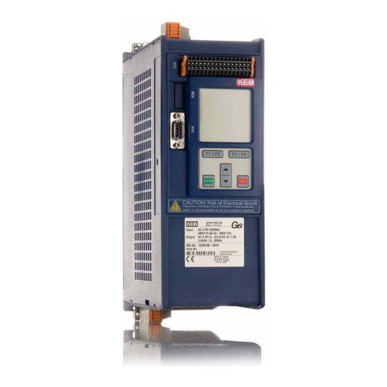
KEB Combivert G6 Manual
Open loop
Hide thumbs
Also See for Combivert G6:
- Programming manual (326 pages) ,
- Instructions for use manual (54 pages) ,
- Instructions for use and installation (52 pages)

Related Manuals for KEB Combivert G6


Summary of Contents for KEB Combivert G6
- Page 1 C O M B I V E R T Customer parameters v/f operation Translation of original manual Document Part version Date 20096630 1214...
-
Page 3: Table Of Contents
Table of contents Table of contents Preface ......................4 Information on special measures ..................4 Documentation ........................4 Validity and liability ......................4 Copyright ..........................5 1.5 Specified application ......................6 Product description ......................6 1.6.1 Corresponding documentation ....................6 Parameter Description ................... 7 Selection of the customer parameter menu ..............7 Password input in CP mode ....................8 CP-Parameter for open-loop operation ................9 Troubleshooting ................... -
Page 4: Preface
Precondition for all further steps is the knowledge and observance of the safety and operating instructions. This is provided accompanied by the de- vice or by the download site of www.keb.de. Non-observance of the safety and operating instructions leads to the loss of any liability claims. -
Page 5: Copyright
Karl E.Brinkmann GmbH agency. Copyright The customer may use the instruction manual as well as further documents or parts from it for internal purposes. Copyrights are with KEB and remain valid in its entirety. , COMBIVERT , COMBICONTROL... -
Page 6: Specified Application
The used semiconductors and components of the Karl E.Brinkmann GmbH are developed and dimensioned for the use in industrial products. If the KEB COMBIVERT G6 is used in machines, which work under exceptional conditions or if essential functions, life-supporting measures or an extraordinary safety step must be fulfilled, the necessary reliability and secu- rity must be ensured by the machine builder. -
Page 7: Parameter Description
Parameter Description Parameter Description On delivery the KEB COMBIVERT G6 is assigned with an user menu, the customer parame- ters (CP-Parameters). These represent a selection of important parameters for the operation. Up to a maximum of 48 customer parameters can be defined from over 500 parameters. -
Page 8: Password Input In Cp Mode
Parameter Description Password input in CP mode CP00 Password input Ex works the frequency inverter is supplied without password protection, this means that all changeable parameters can be adjusted. After parameterizing the unit can be barred against unauthorized access. The adjusted mode is stored. Following password levels are possible: Password level Val- Password Explanation... -
Page 9: Cp-Parameter For Open-Loop Operation
CP-Parameter for open-loop operation CP-Parameter for open-loop operation Resolu- based Default Unit Flag Parameter Range tion CP00 Password input 0…9999 Ud01 CP01 Actual value display -400…400 0,0125 0 Hz ru07 CP02 Set frequency display -400…400 0,0125 0 Hz ru01 CP03 Inverter state 0…255 ru00 CP04 Apparent current... - Page 10 CP-Parameter for open-loop operation CP00 Password input see chapter 2.2 CP01 Actual value display Co-domain Description 0…±400 Hz Display of the actual output frequency in Hz. The rotation of the inverter is displayed by the sign. Examples: 18.3 Output frequency 18,3 Hz, rotation forward -18.3 Output frequency 18,3 Hz, rotation reverse CP02 Set frequency display...
- Page 11 CP-Parameter for open-loop operation CP04 Apparent current Co-domain Description 0…±6553.5 A Display of the actual apparent current in ampere. CP05 Apparent current peak value Co-domain Description 0…±6553.5 A CP05 makes is possible to recognize the max. apparent current. For that the highest value of CP04 is stored in CP05.
- Page 12 CP-Parameter for open-loop operation CP08 DC-link voltage/peak value Co-domain Description 0…1000 V CP08 makes it possible to recognize short-time voltage rises within an operating cycle. For that the highest value of CP07 is stored in CP08. The peak value memory can be cleared by pressing the UP, DOWN or ENTER key or via bus by writing any value you like to the address of CP08.
- Page 13 CP-Parameter for open-loop operation CP12 acc. time forward CP13 dec. time forward (-1 = CP12) Co-domain Setting Description 0.00…300.00 s 5.00 s The parameter determines the time needed to accelerate from 0 Hz to100 Hz or to decelerate from 100 Hz to 0 Hz. The actual acceleration-/ deceleration time is proportion- al to the frequency change (∆f).
- Page 14 CP-Parameter for open-loop operation CP14 S-curve time acceleration forward Co-domain Setting Description 0.00 (off)…5.00 s 0.00 s For some applications it is of advantage when the drive (off) starts and stops jerk-free. This is achieved through a straightening of the acceleration and deceleration ramps. The straightening time, also called S-curve time, can be adjusted with CP14.
- Page 15 CP-Parameter for open-loop operation CP16 Rated frequency Co-domain Setting Description 0.00…400.00 Hz 50 Hz With the adjusted frequency the inverter reaches in controlled operation a maximal output voltage. The adjustment of the rat- ed motor frequency is typical in this case. In order to drive defined ramps with ac- tivated S-curve time, the preset accel- Attention...
- Page 16 CP-Parameter for open-loop operation CP18 Switching frequency Co-domain Setting Description 2 / 4 / 8 / 12 / The switching frequency with which the power modules are 16 kHz clocked can be changed depending on the application. The max.possible switching frequency as well as the factory setting are specified by the power circuit.
- Page 17 CP-Parameter for open-loop operation DC-braking at switch off of the direction of rotation and upon reaching 4 Hz. DC-braking when the real frequency falls below 4 Hz and the drives decelerates DC-braking as soon as the set value falls below 4 Hz. DC braking if prog.
- Page 18 CP-Parameter for open-loop operation CP25 Stall level This function protects the frequency inverter against switch off through overcurrent during constant output frequency. When exceeding the adjusted value, the output frequency is re- duced until the value drops below the adjusted value. "stall" is displayed (CP03) when the function is active.
- Page 19 CP-Parameter for open-loop operation CP27 Response Description Quick stopping, Fast stop - switch off of modulation after reaching modulation off, 0 Hz. Correct the error for the restart and activate restart after reset reset. The drive remains in condition fast stop until Status message „Warning! …“...
- Page 20 CP-Parameter for open-loop operation CP30 ANOUT1 function CP30 defines the function of analog output 1. The output at the analog output is made in a range of 0…±10 V. Value Function Scaling factor 0…100 % (0…±100 %) Absolute actual frequency (CP01) 0…100 Hz Absolute set frequency (CP02) 0…100 Hz...
- Page 21 CP-Parameter for open-loop operation Value Function act. utilization (CP06) > switching level Amount actual active current > switching level DC link voltage (CP07) > switching level Actual value (CP01) > switching level Setpoint (CP02) > switching level Actual torque > switching level Absolute value AN1 >...
- Page 22 CP-Parameter for open-loop operation CP34 comparison level 2 Co-domain Setting Description -30000,00…30000,00 4,00 This parameter determines the switching level for relay output 1. After the switching of the relay, the value can move within a window (hysteresis), without the relay dropping off.
- Page 23 CP-Parameter for open-loop operation CP37 Display Response Restart Immediate disabling of modulation Quick stopping / disabling of modulation after reach- Remove fault; reset ing speed 0 Quick stopping / holding torque at speed 0 Immediate disabling of modulation Quick stopping / disabling of modulation after reach- Autoreset, if no fault ing speed 0 is present...
- Page 24 CP-Parameter for open-loop operation Co-domain Setting Description KEBdef/cust.par/sel.sets. Default values are copied in all parameters of set 0 (exception: system and security parameters). If the target set is > 0 only programmable parameters are copied. KEBdef/cust.par/all sets. Default values are copied in all parameters of all sets (exception: system and security parameters).
-
Page 25: Troubleshooting
Error Messages and their Cause The status display is divided at COMBIVERT G6 in status, error and warning messages. Sta- tus messages display the actual operating condition of the unit.They have no special identifi- cation and are used for information only. - Page 26 Troubleshooting Display Value Meaning The setpoint must be above the level Pn86. If the actual value is below the level, the counter starts. A blockade is recognized if the counter reaches the blockade detected adjusted time in Pn86. The output function do00…07 = 96 (blockade active) is set.
- Page 27 Troubleshooting Display Value Meaning Modulation is switched off after DC braking (see chapter low speed / DC brake brake control). calc. drive data ready 127 Calculation drive data ready base block Power modules for motor de-excitation locked Motor temperature switch or PTC at the terminals T1/T2 no ERROR drive over- is again in the normal operating range.
- Page 28 Troubleshooting Display Value Meaning Error messages Error: During the automatic motor stator resistance mea- ERROR calc. drive data surement. ERROR output phase fail. Phase loss detection at the output A blockade was recognized.Pn85 Bit 4 is at error, no Error blockade auto-reset.
- Page 29 Troubleshooting Display Value Meaning It has been attempted to select a locked parameter set. ERROR set Programmed response “Error, restart after reset”. One phase of the input voltage is missing (ripple-detec- ERROR phase failure tion) Error in a function that is monitored by the optional safety module.
- Page 30 Troubleshooting Display Value Meaning Overtemperature of power module. The error can only be reset at "no E. overheat pow.mod.". Causes: ERROR overheat pow. • insufficient air flow at the heat sink (soiled) mod. • ambient temperature too high • ventilator clogged Error: Undervoltage (DC link circuit).
- Page 31 Troubleshooting Display Value Meaning This warning is output when the defined level is exceed- A.STOP overheat pow. ed. Furthermore the response to this warning can be programmed. Watchdog for the communication between control board and PC (on an optional fieldbus interface) or control ABN.STOP bus board and power unit has responded.
- Page 32 +39 02 3353531 • fax: +39 02 33500790 net: www.keb.de • mail: kebitalia@keb.it KEB Power Transmission Technology (Shanghai) Co.,Ltd. KEB Japan Ltd. No. 435 Qianpu Road, Chedun Town, Songjiang District, CHN-Shanghai 201611, P.R. China 15–16, 2–Chome, Takanawa Minato-ku fon: +86 21 37746688 • fax: +86 21 37746600...
Need help?
Do you have a question about the Combivert G6 and is the answer not in the manual?
Questions and answers