KEB COMBIVERT G6 Installation Manual
Control circuit io-link
Hide thumbs
Also See for COMBIVERT G6:
- Programming manual (326 pages) ,
- Instructions for use manual (54 pages) ,
- Instructions for use and installation (52 pages)

Subscribe to Our Youtube Channel
Related Manuals for KEB COMBIVERT G6


Summary of Contents for KEB COMBIVERT G6
- Page 1 C O M B I V E R T GB Installation Manual IO-link Control Circuit Original manual Mat.No. Rev. 00G6NES-E001...
-
Page 3: Table Of Contents
Table of Contents Preface ......................5 General ..........................5 Safety instructions ......................5 Validity and liability ......................5 Copyright ..........................6 1.5 Specified application ......................6 Product description ......................6 Part code ..........................7 Control circuit IO-Link ..................9 Overview ..........................9 2.1.1 Inverter status LED1 ...................... - Page 4 Table of Contents GB - 4...
-
Page 5: Preface
1). This is provided accompanied by the device tions or by the download site of www.keb.de. Non-observance of the safety and operating instructions leads to the loss of any liability claims. The warnings and safety instructions in this manual work only supplementary. This list is not exhaustive. -
Page 6: Copyright
The used semiconductors and components of KEB are developed and dimensioned for the use in industrial products. If the KEB COMBIVERT F5 is used in machines, which work under exceptional conditions or if essential functions, life-supporting measures or an extraordinary safety step must be fulfilled, the necessary reliability and security must be ensured by the ma- chine builder. -
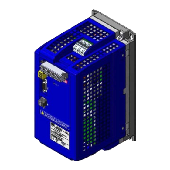
Page 7: Part Code
Preface This accompanying instruction manual contains only information for the installa- tion and connection of the IO-Link control of the KEB COMBIVERT G6. Further parts of the installation manual are required depending on the ordered type: • Connection and adjustments of the power unit •... - Page 8 Preface xx G6 x x x - x x x x without filter, without braking transis- like 0 with like A with tor, f=0Hz without safety function STO without filter, with braking transistor, like 1 with like B with without safety function STO f=0Hz internal filter;...
-
Page 9: Control Circuit Io-Link
Control circuit Control circuit IO-Link The control provides the following functions: • IO-link device interface • Hardware allocation of digital inputs and outputs • Diagnostic interface (parameter display, scope mode) • Hardware of the control circuit „safely separated“ according to EN 61800-5-1 (base TN- C/-S mains) •... -
Page 10: Io-Link Device Interface
3. Plug cable into the round slot, that no wires can be seen from the outside. 4. Remove screw driver and check if cables are fixed. A safe clamping can not be guaranteed when using shorter wire-end ferrules. KEB generally recommends the use of wire-end ferrules in industrial environments. GB - 10... -
Page 11: Diagnosis/Visualisation
Telegram DIN66019II is used as communication protocol. Die RS232/485- Schnittstelle liegt auf dem gleichen Potential wie die Steuerkarte. The correct configuration and language file must be loaded for the operation with COMBIVIS. The download can be done via the KEB homepage. Interface Standard... -
Page 12: Connection Of The Rs485 Interface
Control circuit 2.1.4.3 Connection of the RS485 interface The following instructions must be observed in order to prevent interferences at the RS485 interface: • use in pairs, twisted and shielded cable • Ground outer shield at one side (prior at interference-free side) •... -
Page 13: Wiring Rs485 Half Duplex
Control circuit 2.1.4.5 Wiring RS485 half duplex COMBIVERT COMBIVERT 5 4 3 2 1 5 4 3 2 1 R=120Ω 9 8 7 6 9 8 7 6 Master RXD/TxD-A RXD/TxD-B 1) The ground connection is used to reduce communication disturbances Although the functional earth is connected correctly potential differences be- tween the bus nodes can occur at long lines which disturb the communica- tion. -
Page 14: Control Terminal Strip X2A
1.00 mm². Front view Side view a) Pusher b) Connecting wire hole A safe clamping can not be guaranteed when using shorter wire-end ferrules. KEB generally recommends the use of wire-end ferrules in industrial environments. GB - 14... -
Page 15: Assignment Of The Terminal Strip X2A
Control circuit 2.1.5.2 Assignment of the terminal strip X2A Name Description Specifications Digital mass; Reference potential for digital inputs/outputs and U Input external voltage supply U=24 VDC +20 %/-15 % =400 mA like pin 1 Voltage output for the control of the digital U=24 VDC ±25 % inputs =100 mA... -
Page 16: Connection Of The Digital Inputs
Control circuit Name Description Specifications Analog mass; Reference potential for analog inputs and outputs ANOUT1 Analog output 1 U=0…±10 VDC (max. 11.5 VDC) =10 mA Ri = 100 Ω Resolution= 11Bit + sign like Pin 21 ANOUT2 Analog output 2 like Pin 22 R2-C Relay 2... -
Page 17: Connection Of The Digital Outputs
Control circuit Input Factory setting of the digital inputs Name open-loop operation closed-loop operation reset Control release Direction of rotation reverse Direction of rotation forward Fixed frequen- Fixed value 1 cy 1 Fixed frequency Fixed value 3 Fixed frequen- Fixed value 2 cy 2 External error input (E.EF) Activates the DC braking... -
Page 18: Connection Of The Analog Inputs
Control circuit 2.1.5.5 Connection of the analog inputs Examples for the connection of the analog setpoint input R = 0…3/5/10kΩ 2022 2022 0…±20mA 4…20mA 0…±10Vdc *) Connect potential equalizing line only if a potential difference of >30 V exists between the controls. The internal resistance is reduced to 30 kΩ. Input Factory setting of the setpoint inputs Name... -
Page 19: Connection Of The Relay Outputs
Control circuit 2.1.5.7 Connection of the relay outputs Connection of the relay outputs Specification: U = max. 30 Vdc I = 0.01…1 A 262830 Ohmic load 252729 Output Factory setting of the relay outputs Name open-loop operation closed-loop operation 26/28/30 Fault relay 25/27/29 Frequency-dependent switch... -
Page 20: Parameter Description
Parameter Description Parameter Description On delivery the KEB COMBIVERT G6 is assigned with an user menu, the customer parame- ters (CP-Parameters). These represent a selection of important parameters for the operation. Up to a maximum of 48 customer parameters can be defined from over 500 parameters. - Page 21 Notes GB - 21...
- Page 22 Notes GB - 22...
- Page 23 Notes GB - 23...
- Page 24 +39 02 3353531 • fax: +39 02 33500790 net: www.keb.it • mail: kebitalia@keb.it KEB Power Transmission Technology (Shanghai) Co.,Ltd. No. 435 Qianpu Road, Chedun Town, Songjiang District, KEB Japan Ltd. CHN-Shanghai 201611, P.R. China 15–16, 2–Chome, Takanawa Minato-ku fon: +86 21 37746688 • fax: +86 21 37746600...
Need help?
Do you have a question about the COMBIVERT G6 and is the answer not in the manual?
Questions and answers