KEB COMBIVERT G6 Programming Manual
Hide thumbs
Also See for COMBIVERT G6:
- Programming manual (326 pages) ,
- Instructions for use manual (54 pages) ,
- Instructions for use and installation (52 pages)

Subscribe to Our Youtube Channel
Related Manuals for KEB COMBIVERT G6


Summary of Contents for KEB COMBIVERT G6
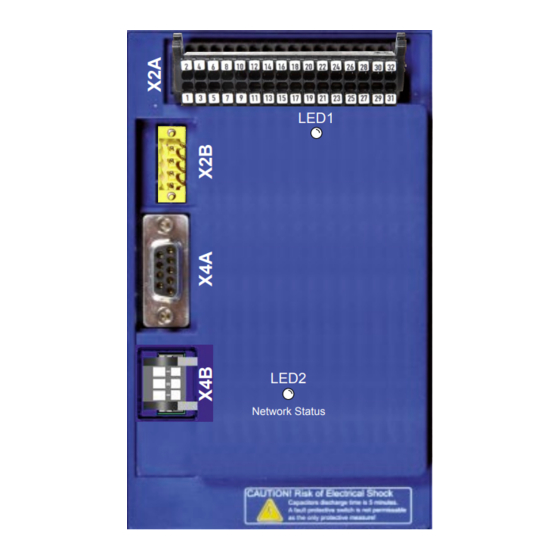
- Page 1 C O M B I V E R T LED1 LED2 Network Status Programming manual COMBIVERT G6 Control unit IO Link Translation of the original manual Document Part Version 20100117...
-
Page 3: Preface
Preface Preface The described hard- and software are developments of the KEB Automation KG. The enclosed documents correspond to conditions valid at printing. Misprint, mistakes and technical changes reserved. Signal words and symbols Certain operations can cause hazards during the installation, operation or thereafter. -
Page 4: Laws And Guidelines
Copyright The customer may use the instruction manual as well as further documents or parts from it for internal purposes. Copyrights are with KEB Automation KG and remain valid in its entirety. Other wordmarks or/and logos are trademarks (™) or registered trademarks (®) of their... -
Page 5: Table Of Contents
Table of Contents Table of Contents Preface ..............................3 Signal words and symbols ......................3 More symbols ..........................3 Laws and guidelines ........................4 Warranty 4 Support 4 Copyright ............................4 Table of Contents ........................... 5 List of Figures ............................7 List of Tables ............................8 Glossary .............................. - Page 6 Table of Contents 4.2 Input process data (client => manager) ..................34 5 Description file (IODD) ..........37 6 Fieldbus Watchdog ............38 7 Events ................39 8 General Control Card Parameters (Operator Functionality) .............. 41 9 LC Display Operation ..........49 9.1 Control elements ...........................
-
Page 7: List Of Figures
List of Figures List of Figures Figure 1: Interleaved mode ......................28 Figure 2: Start-up assistant: PD Mapping ..................37 Figure 3: Control elements ......................49 Figure 4: Power-on indicator ......................50 Figure 5: Main menu ........................51 Figure 6: Basic settings ........................52 Figure 7: Change language......................52 Figure 8: Set start mode........................53... -
Page 8: List Of Tables
List of Tables List of Tables Table 1: assignment of the function keys..................50... -
Page 9: Glossary
OSSD Output switching element; - an output signal that is checked in COMBIVERT KEB drive converters regular intervals on its shutdown. COMBIVIS KEB start-up and parameterizing (safety technology) software Protective earth DC current or voltage PELV Protective Extra Low Voltage... - Page 10 Glossary Synchronous serial interface for encoder Safety function „Safe Torque Off“ in accordance with IEC 61800-5-2 Incremental signal with an output voltage up to 5 V Universal serial bus VARAN Real-time Ethernet bus system...
-
Page 11: Used Standards
Used standards Used standards DGUV regulation 3 Electrical systems and equipment DIN 46228-1 Wire-end ferrules; Tube without plastic sleeve DIN 46228-4 Wire-end ferrules; Tube with plastic sleeve DIN IEC 60364-5-54 Low-voltage electrical installations - Part 5-54: Selection and erection of electrical equipment - Earthing arrangements, protective conductors and protec- tive bonding conductors EN 55011... - Page 12 Used standards drive systems (VDE 0160-102, IEC 61800-2) EN 61800-3 Speed-adjustable electrical drives. Part 3: EMC requirements and specific test methods (VDE 0160-103, IEC 61800-3) EN 61800-5-1 Electrical power drive systems with adjustable speed. Part 5-1: Requirements on the safety - electrical, thermal and energy requirements (VDE 0160-105-1) EN 61800-5-2 Electrical power drive systems with adjustable speed.
-
Page 13: Basic Safety Instructions
Hazards and risks through ignorance. ► Read the instruction manual ! ► Observe the safety and warning instructions ! ► If anything is unclear, please contact KEB Automation KG ! 1.1 Target group This instruction manual is determined exclusively for electrical personnel. Electrical per- sonnel for the purpose of this instruction manual must have the following qualifications: •... -
Page 14: Installation
Basic Safety Instructions Drive converters contain electrostatic sensitive components. ► Avoid contact. ► Wear ESD-protective clothing. Do not store drive converters • in the environment of aggressive and/or conductive liquids or gases. • with direct sunlight. • outside the specified environmental conditions. 1.3 Installation DANGER Do not operate in an explosive environment! ►... -
Page 15: Electrical Connection
Basic Safety Instructions 1.4 Electrical connection DANGER Voltage at the terminals and in the device ! Danger to life due to electric shock ! ► Never work on the open device or never touch exposed parts. ► For any work on the unit switch off the supply voltage and secure it against switching on. -
Page 16: Emc-Compatible Installation
Accordng to EN 60204-1 it is permissible to disconnect already tested com- ponents. Drive converters of the KEB Automation KG are delivered ex works voltage tested to 100% according to product standard. 1.4.3 Insulation measurement An insulation measurement (in accordance with chapter 18.3) with DC... -
Page 17: Start-Up And Operation
Basic Safety Instructions 1.5 Start-up and operation The drive converter must not be started until it is determined that the installation com- plies with the machine directive; Account is to be taken of 60204-1. WARNING Software protection and programming ! Hazards caused by unintentional behavior of the drive! ►... -
Page 18: Maintenance
For applications that require cyclic switching on and off of the drive converter, main- tain an off-time of at least 5 min. If you require shorter cycle times please contact KEB Automation KG. Short-circuit proof The drive converters are conditional short-circuit proof. After resetting the internal pro- tection devices, the function as directed is guaranteed. -
Page 19: Disposal
Drive converters with safety function are limited to a service life of 20 years. Then the devices must be replaced. Drive converters of the KEB Automation KG are professional, electronic devices exclu- sively for further industrial processing (so-called B2B devices). Thus the marking does not occur with the symbol of the crossed-out wheeled bin, but by the word mark and the date of manufacture. -
Page 21: Product Description
The used semiconductors and components of the KEB Automation KG are developed and dimensioned for the use in industrial products. Limitation If the KEB COMBIVERT G6 is used in machines, which work under exceptional condi- tions or if essential functions, life-supporting measures or an extraordinary safety step must be fulfilled, the necessary reliability and security must be ensured by the machine... -
Page 22: Residual Risks
Product Description 2.1.1 Residual risks In spite of the intended use, the drive converter can reach unexpected operating condi- tions in error case, wrong parameterisation, incorrect connection or unauthorized inter- ventions and repairs. This can be: • wrong direction of rotation •... -
Page 23: Type Code
Product Description 2.3 Type code xx G6 x x x - x x x x Cooling (not valid for customer-/special version) Air-cooling (housing C, E), air-cooling/flat rear (housing A, B) Flat rear Control/keyboard/display (not valid for customer-/special version) G6L-G Open-loop without keyboard/display G6L-G Open-loop with keyboard/display G6P-S SCL (Sensorless Closed Loop) without keyboard/display G6P-S SCL (Sensorless Closed Loop) with keyboard/display ASCL (Asynchronous Sensorless Closed Loop) G6L-M... - Page 24 Product Description xx G6 x x x - x x x x Control type Analog/digital (standard) ® 1 IO-Link ® 2 EtherCAT ® 3 reserved VARAN G6 unit type Inverter size...
-
Page 25: Io-Link Interface
IO-Link Interface 3 IO-Link Interface An IO-Link slave (device) interface is implemented according to the IO-Link specifi- cation V1.0. Cyclic process data (PDO) and acyclic parameter data (SPDU - service protocol data unit) are supported for accessing the parameters of the device. The device does not support the standard IO mode (SIO mode). - Page 26 IO-Link Interface Individual values are displayed as COMBIVIS parameters: Id-Text Name Parameter index fb03 Unit identification 0x2183 Meaning Unit identification number Type Variable Data length 32 bit Access read Coding 0...FFFFFFh Standard value: 0 Note Any combination of G6 power unit config ID and control card config ID has its own deviceID (reference table) Id-Text Name Parameter index fb05 IO-Link baud rate 0x2185 Meaning Baud rate IO-Link bus...
-
Page 27: Io-Link Status And Error Message
IO-Link Interface 3.2 IO-Link status and error message The status of the IO-Link state machine is shown in the following parameters. Id-Text Name Parameter index fb01 DLState + MasterCommand 0x2181 Meaning Display for DLState + MasterCommand Type Variable Data length 8 bit Access read... -
Page 28: Frame Types
IO-Link Interface 3.3 Frame types The IO-Link specification defines different telegram types, which differ by the size of the process input and process output data. For the buildup of the communication, the master must determine the communication parameters of the device. One of the relevant informations is the length of the process data. Based on this information, the IO-Link master decides which type of telegram for cyclic data exchange is used.In the phase of the communication setup the master uses the telegram type 0. -
Page 29: Parameterization Data (Spdu)
IO-Link Interface 3.4 Parameterization data (SPDU) The device parameters can be addressed via a 16-bit index plus 8-bit sub-index. About the subindex with the values 1...n each subindices or sets of parameters can be ad- dressed. About the subindex 0, all subindices 1...n addressed simultaneously. If at write access a value can not be written (e.g. -
Page 30: Process Data
IO-Link Interface 3.5 Process data There are each 4 bytes of process data available per direction. The number can not be changed. For each process data object a maximum of 4 objects can be mapped. The data direction is described from the view of the process control (PLC, IPC, ...). Process output data (PD out) are data from the control to G6. -
Page 31: Process Data Mapping
Process Data Mapping 4 Process Data Mapping The setting of the process data assignment is possible via the KEB-specific parameters (fb10-fb19). After successful adjustment of the process data mapping the process data can be processed by the G6 device. After loading of the default values, a standard process data mapping is already set. The number of each mapped parameters (fb14, fb19) has to be written once (default value 2) to activate the process data. - Page 32 Process Data Mapping Id-Text Name Parameter index fb11 PD out subindex 0x218B Type Array Subindex 0 Meaning Number of subindices of this object Data length 8 bit Access read Coding Standard value: 4 Note Subindex 1...4 Meaning The value of the subindex determines the parameter set of the selected PD parameter.
- Page 33 Process Data Mapping Id-Text Name Parameter index fb13 PD out type 0x218D Type Array Subindex 0 Meaning Number of subindices of this object Data length 8 bit Access read Coding Standard value: 4 Note Subindex 1...4 Meaning The value specifies the parameter type of the selected PD pa- rameter. Data length 8 bit Access read / write...
-
Page 34: Input Process Data (Client => Manager)
Process Data Mapping 4.2 Input process data (client => manager) Id-Text Name Parameter index fb15 PD in index 0x218F Type Array Subindex 0 Meaning Number of subindices of this object Data length 8 bit Access read Coding Standard value: 4 Note Subindex 1...4 Meaning... - Page 35 Process Data Mapping Id-Text Name Parameter index fb16 PD in subindex 0x2190 Type Array Subindex 0 Meaning Number of subindices of this object Data length 8 bit Access read Coding Standard value: 4 Note Subindex 1...8 Meaning The value of the subindex determines the parameter set of the selected PD parameter.
- Page 36 Process Data Mapping Id-Text Name Parameter index fb18 PD in type 0x2192 Type Array Subindex 0 Meaning Number of subindices of this object Data length 8 bit Access read Coding Standard value: 4 Note Subindex 1...4 Meaning The value specifies the parameter type of the selected PD pa- rameter. Data length 8 bit Access read / write...
-
Page 37: Description File (Iodd)
Description file (IODD) 5 Description file (IODD) Combivis 6 allows the creation of IO-link device descriptions (IODDs) for the G6 devices with IO-Link interface. The IODDs comply with the specification of version 1.0.1. For this purpose, the process data mapping is set at the startup wizard. After that use the button "device description" to start the IO-Link IODD export: Figure 2: Start-up assistant: PD Mapping... -
Page 38: Fieldbus Watchdog
Fieldbus Watchdog 6 Fieldbus Watchdog The fieldbus watchdog is a function in the IO-Link control card. It is used to trigger an error or warning in the inverter, if certain events are not cyclically repeated within a cer- tain time. The activation of the watchdog is set by the control card parameters fb04 and fb05. The monitoring time and the at exceeding of the monitoring time executed function is set by parameter in the inverter (pn05, pn06). -
Page 39: Events
During the reading of an event, no service data can be exchanged. By this way it is possible to transfer events or states of a device via the IO-Link master to the PLC or visualization. The COMBIVERT G6 supports detailed events. The following events are supported: Cur-... - Page 40 Events Id-Text Name Parameter index fb27 synchronization state 0x219B Meaning State of synchronization to the fieldbus cycle Type Variable Data length 8 bit Access read Coding 0: off (device not synchronous) 1: on (device synchronous) Standard value: 0 Note Id-Text Name Parameter index fb28 pd access time 0x219C Meaning Processing time, which is required, to process the PD data (from...
-
Page 41: General Control Card Parameters (Operator Functionality)
General Control Card Parameters (Operator Functionality) 8 General Control Card Parameters (Operator Function- ality) The operator parameters determine the configuration of the G6 IO-Link control. Further- more, the software version as well as the current state can be read. Id-Text Name Parameter index os00 operator identifier 0x2080 Meaning Displays the control card type, as well as the software version. Type Variable Data length... - Page 42 General Control Card Parameters (Operator Functionality) Id-Text Name Parameter index os04 diag error count 0x2084 Meaning Specifies the number of errors occurred on the diagnostic inter- face. Type Variable Data length 8 bit Access read / write Coding 0...255 Standard value: 0 Note Id-Text Name Parameter index os05 diag response delay time 0x2085 Meaning Sets the minimum response delay time for requests on the diag-...
- Page 43 General Control Card Parameters (Operator Functionality) Id-Text Name Parameter index os07 node ID 0x2087 Meaning This parameter specifies the inverter address for the diagnostic interface (DIN 66019). The parameter is an image of the system parameter Sy06. Type Variable Data length 8 bit Access read / write Coding 0...239 Standard value: 1 Note...
- Page 44 General Control Card Parameters (Operator Functionality) Id-Text Name Parameter index os09 PU max invbusy retries 0x2089 Meaning Number of repetitions that are sent on the internal bus from the power module to the controller if it rejects "inverter busy" error. Type Variable Data length...
- Page 45 General Control Card Parameters (Operator Functionality) Id-Text Name Parameter index os13 operator state 0x208D Meaning Displays the state of the power unit, as well as the image of the power unit parameter of the control card. Type Variable Data length 8 bit Access read...
- Page 46 General Control Card Parameters (Operator Functionality) Id-Text Name Parameter index os15 store mode 0x208F Meaning The memory type of non-volatile parameters must be adjust- ed with this parameter. The parameters will not be stored if the value is "0", the device automatically changes to value "1" after the next "power down".
- Page 47 General Control Card Parameters (Operator Functionality) Id-Text Name Parameter index os19 safety software version 0x2093 Meaning Displays the software version of the safety module. Type Variable Data length 32 bit Access read Coding 0.0.0.0...255.255.255.255 If no safety module is installed, the value "0: no safety function- ality“...
- Page 48 General Control Card Parameters (Operator Functionality) Id-Text Name Parameter index os21 safety information 0x2095 Meaning Displays the error code of the safety module Type Variable Data length 32 bit Access read Coding 0...65535 Standard value: 0 Note Id-Text Name Parameter index os23 current PU ID 0x2097...
-
Page 49: Lc Display Operation
LC Display Operation 9 LC Display Operation For optional assembly of the LC display. 9.1 Control elements Name Function ① Menu bar Inverter parameter ② Function bar ① CP mode Function key 1 Operator parameter Function key 2 Settings Function key 3 Function key 4 ▲... -
Page 50: Function Keys And Toolbar
LC Display Operation 9.1.1.2 Function keys and toolbar The function keys F1...F4 are variable assigned depending on the menu item. The tool- bar displays current assignment of the function keys F1 ... F4. The keys can have the following assignment: Display Function DecHex... -
Page 51: Main Menu
LC Display Operation 9.2.2 Main menu The main menu is the top-level menu. With the keys <▲> and <▼> select the desired submenu. Press <ENTER> to Inverter parameter jump to the selected submenu. CP mode Operator parameter Settings Figure 5: Main menu... -
Page 52: Basic Settings
Basic settings 10 Basic settings To adjust the display to the individual needs select "Settings" in the main menu and confirm with <ENTER>. Language english Start mode CP Mode Font size With the keys <▲> and <▼> select the Font size 2 desired function. Contrast 21 Lightning Auto Press <ENTER>... -
Page 53: Startup Mode
Basic settings 10.2 Startup mode The startup mode determines which display appears at switch on. Language english Press <ENTER> to switch into the input Start mode CP Mode mode to change the parameter value. Font size Font size 2 Contrast 21 With the keys <▲> and <▼> select one Startup mode Lightning... -
Page 54: Contrast Settings
Basic settings The font size 2 determines the display size of the parameter values in CP mode. Language english Press <ENTER> to switch into the input Start mode Mode mode to change the parameter value. Font size Font size 2 Contrast With the keys <▲> and <▼> select one Font size 2... -
Page 55: Setting The Backlight Of The Display
Basic settings 10.5 Setting the backlight of the display The menu item "Lighting" defines the be- havior of the backlight of the LC Display. Language english Press <ENTER> to switch into the input Start mode mode to change the parameter value. Font size Font size 2 Contrast... -
Page 56: Operator Parameter
Operator parameter 11 Operator parameter Use the operator parameters to configure the control card, the fieldbus (if available) and the display. Inverter parameter CP mode With the keys < ▲> and <▼> select Operator parameter Settings "Operator parameter" and confirm with <ENTER>. Figure 14: Operator parameter The control card parameters at the analog / digital control are divided into two groups: Operator parameter... -
Page 57: Parameters For Lc Display Setting
Operator parameter 11.1 Parameters for LC display setting The settings of the LC parameters are completely accepted from the LC display only after restarting the device. Id-Text Name Parameter index dp00 language 0x2780 Meaning A language is selected for the menu and the parameters. If the selected language is not available the parameters are dis- played in English. - Page 58 Operator parameter Id-Text Name Parameter index dp02 font size 0x2782 Meaning It can be selected between font sizes 8.10.13.16 and 24 in the display. Exception: see parameter „font size 2“ Type Variable Data length 8 bit Access read / write Coding 8: 8dpi 10: 10dpi...
- Page 59 Operator parameter Id-Text Name Parameter index dp04 contrast 0x2784 Meaning The contrast settings of the LC display can be changed to opti- mize readability. Type Variable Data length 8 bit Access read / write Coding 0...50 Standard value: 21 Note Id-Text Name Parameter index...
- Page 60 Headquarter KEB Automation KG KEB Antriebstechnik GmbH • Getriebemotorenwerk Südstraße 38 • 32683 Barntrup Wildbacher Straße 5 • 08289 Schneeberg Telefon +49 5263 401-0 • Telefax 401-116 Telefon +49 3772 67-0 • Telefax 67-281 Internet: www.keb.de • E-Mail: info@keb.de Internet: www.keb-drive.de • E-Mail: info@keb-drive.de...
Need help?
Do you have a question about the COMBIVERT G6 and is the answer not in the manual?
Questions and answers