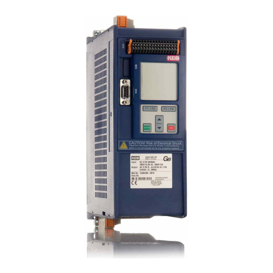
KEB Combivert G6 Instructions For Use And Installation
Housing a
Hide thumbs
Also See for Combivert G6:
- Programming manual (326 pages) ,
- Instructions for use manual (54 pages) ,
- Manual (33 pages)

Subscribe to Our Youtube Channel
Related Manuals for KEB Combivert G6


Summary of Contents for KEB Combivert G6
- Page 1 COMBIVERT G6 INSTRUCTIONS FOR USE | INSTALLATION G6 HOUSING A Translation of the original manual Document 20086425 EN 01...
-
Page 3: Preface
PrefAce Preface The described hard- and software are developments of the KEB Automation KG. The enclosed documents correspond to conditions valid at printing. Misprint, mistakes and technical changes reserved. Signal words and symbols Certain operations can cause hazards during the installation, operation or thereafter. -
Page 4: Laws And Guidelines
The customer may use the instruction manual as well as further documents or parts from it for internal purposes. Copyrights are with KEB Automation KG and remain valid in its entirety. Other wordmarks or/and logos are trademarks (™) or registered trademarks (®) of their... -
Page 5: Table Of Contents
TAbLe Of cONTeNTS Table of contents Preface ..............................3 Signal words and symbols ......................3 More symbols ..........................3 Laws and guidelines ........................4 Warranty ............................4 Support ............................4 Copyright ............................4 Table of contents ........................... 5 List of figures ............................8 List of Tables ............................9 Glossary .............................. - Page 6 3.5.2 Accessories for installation ....................33 3.5.2.1 Mounting kit for G6 housing A ..................33 4 Installation and connection ........34 4.1 Overview of the cOMbIVerT G6 ....................34 4.2 connection of the power unit ....................... 35 4.2.1 Connection of the voltage supply ..................35 4.2.1.1 Wiring instructions ......................
- Page 7 TAbLe Of cONTeNTS 5.2 Storage ............................45 6 Certification ..............46 6.1 ce-Marking ............................. 46 6.2 functional safety ........................... 46 6.2.1 UL Marking .........................46 6.3 further information and documentation ..................49 7 revision History ............50...
-
Page 8: List Of Figures
Figure 4: Mounting distances ......................32 Figure 5: Control cabinet ventilation....................32 Figure 6: Overview of the COMBIVERT G6 ..................34 Figure 7: Input circuit / drive converter type ..................35 Figure 8: Line terminal strip X1A ..................... 36 Figure 9: Connection of the mains supply 230 VAC / 1-phase ............ -
Page 9: List Of Tables
LIST Of TAbLeS List of Tables Table 1: Part code..........................23 Table 2: Climatic ambient conditions ..................... 24 Table 3: Mechanical ambient conditions ..................25 Table 4: Chemical/mechanical active substances ................. 25 Table 5: Equipment classification ....................26 Table 6: Electromagnetic compatibility ..................26 Table 7: Technical data 230V class .................... -
Page 10: Glossary
Overcurrent Fieldbus system Overheat COMBIVERT KEB drive converters Overload COMBIVIS KEB start-up and parameterizing software OSSD Output signal swithching device; - an output signal that is checked in regu- DC current or voltage lar intervals on its shutdown. (safety Demineralized water, also referred to... - Page 11 GLOSSAry The security integrity level is a measure for quantifying the risk reduction. Term used in the safety technology (EN 61508 -1...7). Safety function „Safe stop 1“ in ac- cordance with IEC 61800-5-2 Synchronous serial interface for encoder Safety function „Safe Torque Off“ in accordance with IEC 61800-5-2 Incremental signal with an output voltage up to 5 V...
-
Page 12: Standards For Drive Converters / Control Cabinets
STANDArDS fOr DrIVe cONVerTerS / cONTrOL cAbINeTS Standards for drive converters / control cabinets Product standards that apply directly to the drive converter EN 61800-2 Adjustable speed electrical power drive systems - Part 2: General requirements - Rating specifications for low voltage adjustable frequency a.c. power drive systems (VDE 0160-102, IEC 61800-2) EN 61800-3 Speed-adjustable electrical drives. Part 3: EMC requirements and specific test methods (VDE 0160-103, IEC 61800-3) -
Page 13: Standards That Are Used In The Environment Of The Drive Converter
STANDArDS fOr DrIVe cONVerTerS / cONTrOL cAbINeTS EN 61000-4-4 Electromagnetic compatibility (EMC) - Part 4-4: Testing and measurement techniques - Electrical fast transient/burst immunity test (IEC 61000-4-4); German version EN 61000-4-4 EN 61000-4-5 Electromagnetic compatibility (EMC) - Part 4-5: Testing and measurement techniques - Surge immunity test (IEC 61000-4-5);... -
Page 14: Basic Safety Instructions
Hazards and risks through ignorance. ► Read the instruction manual ! ► Observe the safety and warning instructions ! ► If anything is unclear, please contact KEB Automation KG ! 1.1 Target group This instruction manual is determined exclusively for electrical personnel. Electrical per- sonnel for the purpose of this instruction manual must have the following qualifications: •... -
Page 15: Installation
bASIc SAfeTy INSTrUcTIONS Drive converters contain electrostatic sensitive components. ► Avoid contact. ► Wear ESD-protective clothing. Do not store drive converters • in the environment of aggressive and/or conductive liquids or gases. • with direct sunlight. • outside the specified environmental conditions. 1.3 Installation DANGer Do not operate in an explosive environment! ►... -
Page 16: Electrical Connection
bASIc SAfeTy INSTrUcTIONS 1.4 electrical connection DANGer Voltage at the terminals and in the device ! Danger to life due to electric shock ! ► Never work on the open device or touch exposed parts. ► For any work on the unit switch off the supply voltage and secure it against switching on. -
Page 17: Emc-Compatible Installation
Accordng to EN 60204-1 it is permissible to disconnect already tested com- ponents. Drive converters of the KEB Automation KG are delivered ex works voltage tested to 100% according to product standard. 1.4.3 Insulation measurement An insulation measurement (in accordance with EN 60204-1 chapter 18.3) with DC... -
Page 18: Start-Up And Operation
Never touch terminals, busbars or cable ends. Observe the following instructions if the drive converter for more than one year was not in operation before start-up. https://www.keb.de/fileadmin/media/Manuals/knowledge/04_techinfo/00_ general/ti_format_capacitors_0400_0001_gbr.pdf Switching at the output Switching between motor and drive converter is prohibited for single drives during op- eration as this may trigger the protection gear of the device. -
Page 19: Maintenance
For applications that require cyclic switching on and off of the drive converter, maintain an off-time of at least 5 min after the last switch on. If you require shorter cycle times please contact KEB Automation KG. Short-circuit proof The drive converters are conditional short-circuit proof. After resetting the internal pro- tection devices, the function as directed is guaranteed. -
Page 20: Disposal
Drive converters with safety function are limited to a service life of 20 years. Thereafter the devices must be replaced. Drive converters of the KEB Automation KG are professional, electronic devices exclu- sively for further industrial processing (so-called B2B devices). Thus the marking does not occur with the symbol of the crossed-out wheeled bin, but by the word mark and the date of manufacture. -
Page 21: Product Description
PrODUcT DeScrIPTION 2 Product Description The unit series COMBIVERT G6 concerns to drive converters, which have been devel- oped for the universal use at open-loop three-phase drives. The COMBIVERT is opti- mized for the operation at synchronous and asynchronous motors and equipped with an integrated EMC filter. -
Page 22: Product Features
0.75...1.5 kW / 230 V 0.75...2.2 kW / 400 V Housing size: The COMBIVERT G6 is characterized by the following features: • Operation of three-phase asynchronous motors and three-phase synchronous motors, in operating modes open-loop or closed-loop without speed feedback •... -
Page 23: Part Code
L: like D with f=0 Hz C: Analog/digital (standard) D: CAN® Control type E: IO-Link® F: EtherCAT® I: VARAN Series COMBIVERT G6 Unit size 07…19 Table 1: Part code Not valid at customer/special versions SCL = Sensorless Closed Loop ASCL = Asynchronous Sensorless Closed Loop CANopen®... -
Page 24: Technical Data
3 Technical Data 3.1 Operating conditions 3.1.1 climatic conditions Storage Standard class Notes Surrounding temperature EN 60721-3-1 -25…55 °C Relative humidity 5…95 % (without condensation) EN 60721-3-1 Storage height – – max. 3000 m above sea level Transport Standard class Notes Surrounding temperature EN 60721-3-2... -
Page 25: Mechanical Ambient Conditions
3.1.2 Mechanical ambient conditions Storage Standard class Notes Vibration amplitude 0.3 mm (2…9 Hz) Vibration limits EN 60721-3-1 Acceleration amplitude 1 m/s² (9…200 Hz) Shock limit values EN 60721-3-1 40 m/s²; 22 ms Transport Standard class Notes Vibration amplitude 3.5 mm (2…9 Hz) Vibration limits EN 60721-3-2 Acceleration amplitude 10 m/s²... -
Page 26: Electrical Operating Conditions
3.1.4 electrical operating conditions 3.1.4.1 Equipment classification requirement Standard class Notes – EN 61800-5-1 Overvoltage category EN 60664-1 – Non-conductive pollution, occasional conden- Pollution degree EN 60664-1 sation when PDS is out of service. Table 5: Equipment classification 3.1.4.2 Electromagnetic compatibility The specified values are valid only for devices with external filter. -
Page 27: Technical Data G6 230V Class
5) The voltage at the motor is dependent on the series-connected units and on the control method, see „Calculation of the motor voltage“. The technical data are for 2/4-pole standard motors. With other pole numbers the drive converter must be dimensioned onto the motor rated current. Contact KEB for special or medium frequency motors. -
Page 28: Technical Data G6 400V Class
6) The voltage at the motor is dependent on the series-connected units and on the control method, see „Calculation of the motor voltage“. The technical data are for 2/4-pole standard motors. With other pole numbers the drive converter must be dimensioned onto the motor rated current. Contact KEB for special or medium frequency motors. -
Page 29: Overload And Derating
„hard“ power systems or when under permanent drive load (continuous duty). For con- tinuous duty (S1) drives with a medium duty of > 60%, KEB provided the use of mains chokes with a terminal voltage (Uk) of 4%. -
Page 30: Figure 2: Overload Characteristic
TecHNIcAL DATA G6 400V cLASS t / s N / % 105 110 115 120 125 130 135 140 145 150 160 170 180 190 200 210 220 Figure 2: Overload characteristic On exceeding a load of 105% the overload integrator starts. When falling below the integrator counts backwards. -
Page 31: Dimensions And Weights
DIMeNSIONS AND WeIGHTS 3.5 Dimensions and weights Housing size Weight 1.3 kg Dimensions All dimensions in mm Figure 3: Dimensions and weights for G6 housing A... -
Page 32: Control Cabinet Installation
DIMeNSIONS AND WeIGHTS 3.5.1 control cabinet installation The power dissipation for the control cabinet dimension is to be taken from the technical data. Mounting distances Dimension Distance in mm Distance in inch 1) Distance to preceding elements in the control cab- inet door. -
Page 33: Accessories For Installation
DIMeNSIONS AND WeIGHTS 3.5.2 Accessories for installation 3.5.2.1 Mounting kit for G6 housing A A mounting kit is available for large surface of the shieldings of the connecting cables and as strain relief: Material number Name B0G6T88-0001 Mounting kit for G6 housing A... -
Page 34: Installation And Connection
OVerVIeW Of THe cOMbIVerT G6 4 Installation and connection 4.1 Overview of the cOMbIVerT G6 Housing A Name Description Terminal strip for three-phase motor , braking resistor and DC supply Temperature monitoring; Connection for external PTC or temperature switch Diagnostic interface;... -
Page 35: Connection Of The Power Unit
4.2 connection of the power unit 4.2.1 connection of the voltage supply The COMBIVERT G6-A corresponds to the drive converter type A1. This type can be supplied both by mains and via DC terminals. The starting current limiting is arranged before the DC link. When using as... -
Page 36: Line Terminal Strip X1A
cONNecTION Of THe POWer UNIT 4.2.1.2 Line terminal strip X1A Tightening Name function cross-section torque mm² without with wire-end wire-end Mains 0.5…0.6 A ferrule ferrule L1, N connection 5…6 lb-inch 1-phase 24...14 0.2…2.5 Stranded wire mm² without with wire-end wire-end Mains 0.5…0.6 A ferrule... -
Page 37: Ac Connection
RCMA with separator or RCD type B Insulation monitor Mains fuses Type gG or MCCB Mains contactor Mains choke 07 or 09Z1B02-1000 KEB COMBIVERT Figure 9: Connection of the mains supply 230 VAC / 1-phase 4.2.2.2 AC supply 400V / 3-phase T1 T2 Legend Mains voltage... -
Page 38: Cross-Section Of The Supply Cable
T1 T2 230V class: 275…373 Vdc DC voltage 400V class: 480…746 Vdc Type aR Fuses Pay attention to the permissible voltage range ! KEB COMBIVERT Figure 11: Connection at DC voltage supply 4.2.3.1 Terminal strip X1B DC connection Name function cross-section Tightening torque mm²... -
Page 39: Cable-Fed Disturbances Depending On The Motor Line Length At Ac Supply
25 m 50 m 50 m 100 m < 5 mA The line length can be extend significant by using motor chokes or filters. KEB recommends the use of motor chokes or filters for a line length upto 50 m. Motor chokes or filters are absolutely necessary upto 100 m. 4.2.4.3 Motor line length at operation with DC voltage The maximum motor line length at DC operation is basically dependent on the capacity of the motor cable. The internal filter is not active at DC operation. External measures must be taken here, if necessary. The following data apply for operation under nominal rating conditions. -
Page 40: Terminal Strip X1B Motor Connection
11 lb inch Figure 13: Terminal strip X1B motor connection 4.2.4.8 Wiring of the motor KEB COMBIVERT Apply motor cable, shielding on both sides over a large surface on the function earth Three-phase motor T1 T2 Temperature monitoring (optional) „Connection of a temperature detection“... -
Page 41: Connection Of A Braking Resistor
Wiring of an intrinsically safe braking resistor ATTENTION Only "intrinsically safe" braking resistors are permissible for this oper- ation, since these resistors interrupt themselves at fault such as safety fuse without fire risk. Technical data and design for intrinsically safe braking re- sistors. www.keb.de/fileadmin/media/Manuals/dr/ma_dr_safe-braking-resis- tors-20106652_en.pdf... -
Page 42: Connection Of A Temperature Detection
4.2.6 connection of a temperature detection 4.2.6.1 Temperature detection terminals T1, T2 The KEB COMBIVERT G6 is delivered with a PTC evaluation. The function corresponds to DIN EN 60947-8 and works in accordance with the following table: function of T1, T2... -
Page 43: Use Of The Temperature Detection
cALcULATION Of THe MOTOr VOLTAGe 4.2.6.3 Use of the temperature detection The temperature detection provides the user all possibilities within the resistance range specified in „Temperature detection terminals T1, T2“ . This can be: Thermal contact (NC contact) e.g. at the brake resistor Temperature sensor (PTC) e.g. -
Page 44: Maintenance
Examine and clean extracted air filter and cooling air filter of the con- Monthly trol cabinet. Examine function of the fans of the KEB COMBIVERT. The fan must be replaced in case of audible vibrations or squeak. Make a visual leak test of the cooling circuit for water-cooled drive converters. Table 10:... -
Page 45: Storage
If the capacitor starts running with rated voltage, it is tried to build the oxide film abrupt again. This causes heat and gas and leads to the destruction of the capacitor. In order to avoid defectives, the KEB COMBIVERT must be started up depending on the storage period in accordance with the following specification: Storage period < 1 year •... -
Page 46: Certification
EN 61800-5-1 used. 6.2.1 UL Marking Acceptance according to UL is marked at KEB drive converters with the adjacent logo on the nameplate. To be conform according to UL for use on the North American and Canadian Market the following additionally instructions must be observed (original text of the UL-File): •... - Page 47 fUNcTIONAL SAfeTy • ”Integral solid state short circuit protection does not provide branch circuit protec- tion. Branch circuit protection must be provided in accordance with the Manufacturer Instructions, National Electrical Code and any additional local codes”. • Wiring terminals are marked to show a range of values or a nominal value of tighten- ing torque in pound-inches to be applied to the clamping screws as shown below: Input/Output terminals: 5…7 lb-in (0.56…0.79 Nm) •...
- Page 48 fUNcTIONAL SAfeTy II) Listed (DIVQ, DIVQ7/CSA Certified ) Circuit Breakers, Type, manufacturer and elec- trical ratings as specified below: Cat. No. Housing Type Manufacturer Ratings 5SJ4 318-8HG42 Siemens S203UP-K 15 07G6 480Y/277V, 15A FAZ D15/3-NA Eaton 1489 A3D 150 Allen Bradley 5SJ4 318-8HG42 Siemens S203UP-K 15 09G6 480Y/277V, 15A FAZ D15/3-NA Eaton 1489 A3D 150 Allen Bradley 5SJ4 318-8HG42 Siemens...
-
Page 49: Further Information And Documentation
INfOrMATION AND DOcUMeNTATION 6.3 further information and documentation You find supplementary manuals and instructions for the download under www.keb.de/service/downloads General instructions • EMC and safety instructions • Manuals for further control boards Service notes • Download of parameter lists • Error Messages Instruction and information for construction and development •... -
Page 50: Revision History
Type code extended to VARAN: Technical data have been adapted; Voltages for DC 2014-04 operation; UL certification adapted Version Date Description 2014-04 Changed to document number. Revision 1G is identical to version 00 2018-03 Insertion of dimensions. Conversion to new KEB corporate identity optics... - Page 51 Tel: +55 16 31161294 E-Mail: roberto.arias@keb.de Room 1709, 415 Missy 2000 725 Su Seo Dong Gangnam Gu 135- 757 Seoul Republic of Korea Tel: +82 2 6253 6771 Fax: +82 2 6253 6770 E-Mail: vb.korea@keb.de Société Française KEB SASU france Z.I.
Need help?
Do you have a question about the Combivert G6 and is the answer not in the manual?
Questions and answers