KEB COMBIVERT G6 Instructions For Use Manual
Installation g6 control analog/digital
Hide thumbs
Also See for COMBIVERT G6:
- Programming manual (60 pages) ,
- Instructions for use manual (54 pages) ,
- Instructions for use and installation (52 pages)

Related Manuals for KEB COMBIVERT G6


Summary of Contents for KEB COMBIVERT G6
- Page 1 COMBIVERT G6 INSTRUCTIONS FOR USE | INSTALLATION G6 CONTROL ANALOG / DIGITAL Translation of the original manual Document 20138187 EN 00...
-
Page 3: Preface
PRefACe Preface The described hard- and software are developments of the KEB Automation KG. The enclosed documents correspond to conditions valid at printing. Misprint, mistakes and technical changes reserved. Signal words and symbols Certain operations can cause hazards during the installation, operation or thereafter. -
Page 4: Laws And Guidelines
Copyright The customer may use the instruction manual as well as further documents or parts from it for internal purposes. Copyrights are with KEB Automation KG and remain valid in its entirety. Other wordmarks or/and logos are trademarks (™) or registered trademarks (®) of their... -
Page 5: Table Of Contents
TAbLe Of CONTeNTS Table of Contents Preface ..............................3 Signal words and symbols ......................3 More symbols ..........................3 Laws and guidelines ........................4 Warranty ............................4 Support ............................4 Copyright ............................4 Table of Contents ........................... 5 List of figures ............................6 List of Tables ............................6 Glossary .............................. -
Page 6: List Of Figures
LIST Of fIGUReS List of figures Notes 26 Figure 1: Overview ..........................15 Figure 2: Keyboard and display ...................... 16 Figure 3: Assignment of the interface X4A ..................17 Figure 4: Serial cable to connect the control board with a PC ............17 Figure 5: Wiring RS485 full duplex.................... -
Page 7: Glossary
Fieldbus system regular intervals on its shutdown. COMBIVERT KEB drive converters (safety technology) COMBIVIS KEB start-up and parameterizing Protective earth software PELV Protective Extra Low Voltage DC current or voltage Term used in the safety technolo- German Institut for standardization gy (EN 61508-1...7) for the size of... - Page 8 GLOSSARy Safety function „Safe Torque Off“ in accordance with IEC 61800-5-2 Incremental signal with an output voltage up to 5 V Universal serial bus VARAN Real-time Ethernet bus system...
-
Page 9: Used Standards
USeD STANDARDS Used standards DGUV regulation 3 Electrical systems and equipment DIN 46228-1 Wire-end ferrules; Tube without plastic sleeve DIN 46228-4 Wire-end ferrules; Tube with plastic sleeve DIN IEC 60364-5-54 Low-voltage electrical installations - Part 5-54: Selection and erection of electrical equipment - Earthing arrangements, protective conductors and protec- tive bonding conductors EN 55011... - Page 10 USeD STANDARDS EN 61800-3 Speed-adjustable electrical drives. Part 3: EMC requirements and specific test methods (VDE 0160-103, IEC 61800-3) EN 61800-5-1 Electrical power drive systems with adjustable speed. Part 5-1: Requirements on the safety - electrical, thermal and energy requirements (VDE 0160-105-1) EN 61800-5-2 Electrical power drive systems with adjustable speed. Part 5-2: Requirements on the safety –...
-
Page 11: Basic Safety Instructions
DGUV regulation 1.2 Validity of this manual This manual describes the control part of the COMBIVERT G6 Analog/Digital. The manual • contains only supplementary safety instructions. • is only valid in connection with the power unit manual of COMBIVERT G6. -
Page 12: Electrical Connection
bASIC SAfeTy INSTRUCTIONS 1.3 electrical connection DANGeR Voltage at the terminals and in the device ! Danger to life due to electric shock ! ► For any work on the unit switch off the supply voltage and secure it against switching on. ►... -
Page 13: Product Description
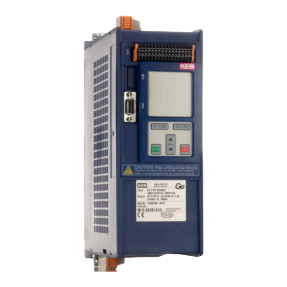
PRODUCT DeSCRIPTION 2 Product Description The product family COMBIVERT G6 has been developed for the universal use at open- loop three-phase drives. The COMBIVERT G6 can be operated open-loop or encoder- less speed or torque-controlled. The units are equipped with an integrated EMC filter. ATTENTION This accompanying instruction manual contains only information for the installation and connection of the control of the KEB COMBIVERT G6. -
Page 14: Table 1: Part Code
® 5 Control type F: EtherCAT ® 6 H: Reserved I: VARAN Series COMBIVERT G6 Inverter size 07…19 Table 1: Part code Not valid for customer / special versions SCL = Sensorless Closed Loop ASCL = Asynchronous Sensorless Closed Loop CANopen®... -
Page 15: Control Circuit Analog/Digital
CONTROL CIRCUIT ANALOG/DIGITAL 3 Control Circuit Analog/Digital The control circuit provides the following analog and digital functions: • Hardware allocation of digital and analog inputs and outputs. • Diagnostic interface (parameter display, scope mode) • Hardware of the control circuit „safely separated“ according to EN 61800-5-1 (base TN-C/-S mains) •... -
Page 16: Keyboard And Display
CONTROL CIRCUIT ANALOG/DIGITAL 3.1.2 Keyboard and display Depending on the ordered variant the COMBIVERT G6 is equipped with or without key- board/display. LCD display, 160 x 160 pixel, 32 levels of grey The LCD display offers a clear display of the information with plain text display. -
Page 17: Assignment Of The Interface X4A
CONTROL CIRCUIT ANALOG/DIGITAL 3.2 Assignment of the interface X4A reserved reserved TxD (RS232) DGND (reference potential) RxD (RS232) TxD-A (RS485) RxD-A (RS485) TxD-B (RS485) RxD-B (RS485) Figure 3: Assignment of the interface X4A 3.2.1 Connection of the RS232 interface A RS232 cable is required to connect the control board with a PC. Transmission rate of 1.2…100 kBaud is possible. -
Page 18: Wiring Rs485 Full Duplex
CONTROL CIRCUIT ANALOG/DIGITAL 3.2.3 Wiring RS485 full duplex COMBIVERT COMBIVERT 5 4 3 2 1 5 4 3 2 1 R=120Ω 9 8 7 6 9 8 7 6 TxD-A TxD-B Master RxD-A RxD-B 1) The ground connection is used to reduce communication disturbances Figure 5: Wiring RS485 full duplex 3.2.4 Wiring RS485 half duplex... -
Page 19: Control Terminal Strip X2A
Side view a) Pusher b) Connecting wire hole Figure 7: Assembly of the wires ATTENTION A safe clamping can not be guaranteed when using shorter wire-end ferrules. KEB generally recommends the use of wire-end ferrules in industrial environments. -
Page 20: Assignment Of The Terminal Strip X2A
CONTROL CIRCUIT ANALOG/DIGITAL 3.3.2 Assignment of the terminal strip X2A Name Description Specifications Digital mass; Reference potential for digital inputs/out- puts and U Input external voltage supply U=24 VDC +20 %/-15 % =400 mA like pin 1 Voltage output for the control of the digital inputs U=24 V ±25 % =100 mA =Pin 4+32) -
Page 21: Figure 8: Assignment Of The Terminal Strip X2A
CONTROL CIRCUIT ANALOG/DIGITAL Name Description Specifications U=0…±10 VDC (max. 11.5 VDC) Analog output 1 =10 mA Ri = 100 Ω Resolution= 11Bit + sign like pin 21 Analog output 2 like pin 22 R2-C Relay 2 Switching contact = 30 V DC I = 0.01…1 A R1-C Relay 1 Switching contact... -
Page 22: Connection Of The Digital Inputs
CONTROL CIRCUIT ANALOG/DIGITAL 3.3.3 Connection of the digital inputs With internal voltage supply With external voltage supply 6 8 10 6 8 10 Input factory setting of the digital inputs Name Open-loop operation Closed-loop operation Reset Control release Reverse direction of rotation Forward direction of rotation Fixed frequency 1 Fixed value 1... -
Page 23: Connection Of The Analog Inputs
CONTROL CIRCUIT ANALOG/DIGITAL 101214 9 11 13 Output factory setting of the digital outputs Name Switches at actual value=setpoint Ready signal Figure 11: Examples for the connection of the digital outputs 3.3.5 Connection of the analog inputs R = 0…3/5/10kΩ 2022 2022 0…±20mA... -
Page 24: Connection Of The Analog Outputs
CONTROL CIRCUIT ANALOG/DIGITAL 3.3.6 Connection of the analog outputs 0…±10Vdc 0…±10Vdc 10mA 10mA max= max= 2224 Output factory setting of the analog outputs Name Open-loop operation Closed-loop operation Actual value display (CP01) Actual value display (CP01) 0…±400 Hz 0…±4000 rpm Apparent current 0…2•IoutN Figure 14: Connection of the analog outputs... -
Page 25: Parameter Description
PARAMeTeR DeSCRIPTION 4 Parameter Description On delivery the KEB COMBIVERT G6 is assigned with an user menu, the customer parameters (CP-Parameters). These represent a selection of important parameters for the operation. Up to a maximum of 48 customer parameters can be defined from over 500 parameters. Only parameter CP00 password input is predefined and can not be modified or deleted. CP48 software version Value range Setting Description 0.0.0.0 …... -
Page 26: Notes
NOTeS Notes... - Page 27 Tel: +55 16 31161294 E-Mail: roberto.arias@keb.de Room 1709, 415 Missy 2000 725 Su Seo Dong Gangnam Gu 135- 757 Seoul Republic of Korea Tel: +82 2 6253 6771 Fax: +82 2 6253 6770 E-Mail: vb.korea@keb.de Société Française KEB SASU france Z.I.
Need help?
Do you have a question about the COMBIVERT G6 and is the answer not in the manual?
Questions and answers