Table of Contents
Advertisement
Advertisement
Table of Contents

Summary of Contents for JS Automation YPV-040
- Page 1 Mokon Series Driver User’s Manual V2.1 健昇科技股份有限公司 JS AUTOMATION CORP. 新北市汐止區中興路 100 號 6 樓 6F., No.100, Zhongxing Rd., Xizhi Dist., New Taipei City, Taiwan TEL:+886-2-2647-6936 FAX:+886-2-2647-6940 http://www.automation.com.tw http://www.automation-js.com/ E-mail:control.cards@automation.com.tw...
- Page 2 Correction record Version Record Add CN1-9 TLM+ Torque limit command 1 Adjust 5. I/O Signal Definitions and CN1 Pin Assignments 2 Add 20. Wiring of MPC3024 wiring board to Mokon driver 3 Modify description of CN1 Pin16 Hold 1. Chapter 5 I/O Signal Definitions and CN1 Pin Assignments Pin5,6,7,13,14,15,16,30,31,34 descriptions—rewrite for more detail Pin1,2 description—rewrite for more detail 1.
- Page 3 Contents 1. Checking Mokon series products on delivery 1.1 Servomotor nameplate descriptions 1.2 Servomotor model 1.3 Servo drive nameplate descriptions 1.4 Servo drive model 1.5 Servo drive part names 2. Servo drive installation precautions 2.1 Prevent foreign object intrusion 3. Servo drive wiring precautions 3.1 Main wiring 3.2 Wiring for the controller and the encoder 4.
- Page 4 12.8 VCMD+ and TCMD+ inputs (CN1-1 and CN1-8) 12.9 TLCMD+ Torque limit analog command input (CN1-9) +PPCMD –PPCMD, +NPCMD -NPCMD Position command inputs (CN1-26~29) 12.10 12.11 SPD1 SPD2 SPD3 Internal speed switching inputs (CN1-32~35) 13. Descriptions of Mokon servo drive Output signals 13.1 Output Signal definitions and CN1 pin assignments 13.2 ALM Servo alarm output (CN1-10) 13.3 Brake motor brake release output (CN1-17)
- Page 5 Customer’s right to recover damages caused by fault or negligence on the part of JS automation Corp. shall be limited to the amount theretofore paid by the customer. JS automation Corp. will not be liable for damages resulting from loss of data, profits, use of products, or incidental or consequential damages, even if advised of the possibility thereof.
-
Page 6: Checking Mokon Series Products On Delivery
1. Checking Mokon series products on delivery Follow the procedure below to check Mokon Series products upon delivery Check the following items when Mokon Series products are delivered: Check the packed products for damages that may have occurred during shipping. Check whether the name and number of the delivered products are the same as those on the delivery sheet. -
Page 7: Servomotor Model
1.2 Servomotor model YBL13S75 - L Z Servomotor Serial Number Design Revisions: K Shaft length 20mm Servomotor Pole Number S Shaft length 15mm and Encoder Resolution B With brake C 8P1024 P/R Q Special shaft D 8P2048 P/R U Terminal box type E 4P2500 P/R V Oblique shaft F 4P5000 P/R... -
Page 8: Servo Drive Model
1.4 Servo drive model YPV - 300-V YPV Series Servo drive Servodrive Capacity 040 0.4 KW 600 6 KW 055 0.55 KW 750 7.5 KW 075 0.75 KW 860 8.6 KW 100 1 KW 1100 11 KW 150 1.5 KW 1500 15 KW 200 2 KW 2200 22 KW... -
Page 9: Servo Drive Part Names
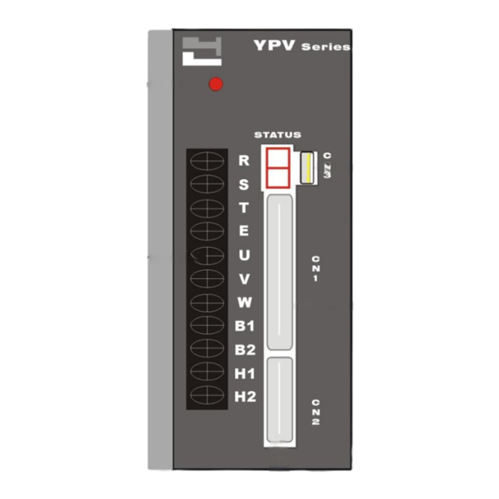
1.5 Servo drive part names The figure below shows the part names of the servo drive. CN3 Communication Connector Used to communicate with a personal computer (RS-232) or a control panel Charge Indicator Lights when the main circuit power supply is ON and stays as long as the main circuit power supply capacitor remains charged. -
Page 10: Servo Drive Installation Precautions
2. Servo drive installation precautions The servo drive should be stored in the environment with ambient temperature range of 0-55 C (no freezing) and relative humidity under 90% RH (no condensation). Installation Orientation and Spacing: When installing the servo drive, make the front panel containing connectors face outward and take into consideration the easy connection/disconnection of CN1 and CN2 connectors for measurement. - Page 11 Extra Notices: 1. Do not install the servo drive in locations likely to be affected by oil and dust. If unavoidable, please install the Servo drive in the airtight control cabinet and consider using ventilation filter. Also use a protective cover over the Servomotor. 2.
-
Page 12: Servo Drive Wiring Precautions
3. Servo drive wiring precautions Wiring precautions 3.1 Main wiring 1. Apply three-phase 220V AC mains through the NFB to the magnetic contactor, then connect to the servo drive RST terminals. Consider installing a reactor and linear noise filter if the local power supply quality is poor. -
Page 13: Wiring For The Controller And The Encoder
3.2 Wiring for the controller and the encoder 1. Each pin of CN1 and CN2 must be soldered and checked carefully for correct pin number Check the adjacent pins after soldering to avoid being incidentally shorted circuit by the solder or unused leads. 2. -
Page 14: Servomotor Installation Precautions
4. Servomotor installation precautions 4.1 Installation precautions Try to avoid water and oil exposure since the servomotor contains no water-proof structure. Install a water-proof cover if it is used in a location that is subject to water or oil. 1. Servomotor cable line facing downward can prevent the oil and water from entering the servomotor via cable line. -
Page 15: Alignment
Avoid violent collision and vibration of servomotor when mounting a belt wheel or a clutch! The encoder connecting with the shaft is vulnerable under intense vibration which may adversely affect the resolution and service life of the servomotor. 5. Do not change the encoder wiring direction. 6. -
Page 16: Handling Oil And Water
4.4 Handling oil and water Install a protective cover over the servomotor if it is used in a location subject to water or oil mist. Also use a servomotor with an oil seal to seal the through shaft section. 4.5 Cable stress Make sure there are no bends or tension on the power lines. -
Page 17: Encoder Wiring And Cn2 Pin Assignments Of The Servo Drive
5. Encoder wiring and CN2 pin assignments of the servo drive Motor RSO Motor Side Name of the Servo drive Connector Cable Color Signal Side Pin No. Green White Grey Gray White Gray Yellow White Yellow Brown White Brown Orange White Orange Blue White Blue... -
Page 18: Position Command Input Circuit
6. Position command input circuit 6.1 From differential type line driver 6.2 From open-collector output: Example 1: Using an external power supply provided by the user Note: Mokon Servo drive can be only connected with 24V external power supply. Example 2: Using power supply built in the servo drive... -
Page 19: Analog Command Input Circuit
7. Analog command input circuit Analog command input circuit Digital input circuit interface... -
Page 20: Output Interface Circuits
8. Output interface circuits Digital output interface Example 1: Connecting to a relay output circuit Example 2: Connecting to a photo coupler output circuit... -
Page 21: Encoder Digital Output Interface Circuit
Encoder digital output interface circuit... -
Page 22: Position Control Interface
9. Position control interface... -
Page 23: Speed Control Interface
10. Speed control interface... -
Page 24: Torque Control Interface
11. Torque control interface... -
Page 25: Descriptions Of Mokon Servo Drive Input Signals
12. Descriptions of Mokon servo drive input signals 12.1 Input Signal definitions and CN1 pin assignments Signal Function Descriptions Type Name ±15V volt with allowable 50mA output , spare for Common +15V +15V voltage output external analog use. -15V -15V voltage output Common power ground for user control interface. - Page 26 Signal Type Pin Name Pin No. Function Descriptions SPEED VCMD+ Speed command During driver set at speed mode: Enable the motor to run at speed proportional to the speed command voltage . At ±10V input , the motor runs ±3000rpm , or ±2000rpm .
- Page 27 Signal Type Pin Name Pin No. Function Descriptions Position External Power +24V External Power input for open collector input pulse driver. Command (If TTL or line driver pulse source, the EPI power input is no need) Ref 7. Position Command Input Circuit +PPCMD Forward rotation Forward rotation pulse Input+...
- Page 28 12.2 Servo ON input (CN1-6) This signal is used to turn on and off the power to the servomotor. Note: 1. Contact this input to ground will make the Mokon driver ready to receive the command pulse or analog voltage input. 2.
- Page 29 12.5 PRIH Forward rotation inhibited and NRIH reverse rotation inhibited inputs (CN1-14~15) These two signals force the moving part of the apparatus to stop if they travel over the allowable range of motion. Connect the overtravel limit-switch signals to the correct pins (PRIH for forward overtravel, NRIH for reverse overtravel) of the servo drive CN1 connector.
-
Page 30: Mdo Operation Mode
12.7 MDO Operation mode If the CNTL parameter is set in the “Common Parameter” menu as S/P (speed/Position), P/T (Position/Torque), or S/T (Speed/Torque) mode, this input signal enables the switching between operation modes. For example: If CNTL is set as S/P mode, when CN-34 and 24G is not connected, the servo drive is in Speed operation mode, when connected;... -
Page 31: Ppcmd –Ppcmd, +Npcmd -Npcmd Position Command Inputs (Cn1-26
12.9 TLCMD+ Torque limit analog command input (CN1-9) This signal is used as analog torque limit command input when CN1-13 is connected with 24G. If the input voltage is 10V, the limit range corresponds to 300% of the rated torque of the motor. 12.10 +PPCMD –PPCMD, +NPCMD -NPCMD Position command inputs (CN1-26~29) When the servo drive is in P Mode or switched to Position operation mode, these signals are used as position command inputs. - Page 32 12.11 SPD1 SPD2 SPD3 Internal speed switching inputs (CN1-32~35) ELGN1 ELGN2 ELGN3 Electronic Gear Numerator Switching Inputs (CN1-32~35) When the servo drive is in S Mode or switched to Speed operation mode, and if the internal speed is enabled, the internal speed command can be selected by properly connecting one among CN1-32 (SPD1), CN1-33(SPD2) and CN1-35(SPD3) to 24G.
-
Page 33: Descriptions Of Mokon Servo Drive Output Signals
13. Descriptions of Mokon servo drive Output signals 13.1 Output Signal definitions and CN1 pin assignments Signal Type Pin Name Pin No. Function Descriptions Common Servo Alarm Digital signal for alarm BRAKE Motor Brake Digital signal for releasing the motor Release Signal brake Speed... - Page 34 13.2 ALM Servo alarm output (CN1-10) This signal indicates that an abnormal state of the servo drive occurs. 13.3 Brake motor brake release output (CN1-17) If CN-17 is programmed as the brake release signal, when the driver is enabled through the contact of SON (CN 1-6) and 24G, the brake release signal will be issued after a delay time defined by the MBR parameter in the “Common Parameter”menu.
- Page 35 13.4 Zero servo speed zero output (CN1-36) This signal is used to indicate that the speed of the servomotor is lower than or equal to the ZSPD parameter set in the “Speed Parameter” menu and issued by connecting CN1-36 to 24G. 13.5 ITLM In torque limit output (CN1-37) When the servo drive CN1-13 (TLM) is connected with 24G or if the output torque is saturated at the limit set by the driver, CN1-37 will be connected with 24G to issue the In Torque Limit signal.
- Page 36 13.7 MON1 MON2 Analog monitor outputs (CN1-11~12) These output signals are for monitoring the dynamic states of the servo drive and can be selected in the “Common Parameter” menu, in which the scale, offset and resolution of the output signals are also defined MON1: as Monitor Channel A defined the “Common Parameter”...
-
Page 37: User Parameter Settings And Functions
14. User parameter settings and functions 14.1 Parameter settings and functions YPV driver parameter definitions parameter register function/data mode initial unit range remark EEPW 0:write parameters into EEPROM S、P、T CNTL Servo control mode 0 ~ 5 0 = Torque mode 1 = Speed mode 2 = Position mode 3 = Speed/Position mode... - Page 38 profile, if use external profile generator set this parameter to deceleration time for speed mode S acceleration profile. 10000 Note: internal generated profile, if use external profile generator set this parameter to PACC Pulse mode control acceleration time. 10000 Note: internal generated profile, if use external profile generator set this parameter to 0: internal speed generator...
- Page 39 speed/torque mode ZSPD zero speed range Note: when motor speed rated equivalent voltage less than the setting voltage the CN1-37 (ZERO) will make. speed agreed range. 2000 Note: when motor speed rated equivalent voltage less than the setting voltage the CN1-18 (INS) will make.
- Page 40 rated KPP1 proportional gain for position loop 30000 Not available SSPD speed loop gain switch level (speed lower than SSPD, switch from gain1 to gain2) CNTR Refer appendix 1 S、P、T 0~1 DO17 function configuration of CN1-17 0: active while servo ready 1: brake release while P037 (MBR) time out...
- Page 41 MONT2 source of monitor output2 0 ~ 2 0:servo motor current 1:speed 2:position error counter MONL speed monitor output voltage 0 ~ 10 of rated speed ±10V =±2000 OR ±3000 ±8V = ±2000 OR ±3000 RPM MTYP Motor pole number pole 2 ~ 48 Motor rated RPM...
- Page 42 0: positive command voltage in CCW direction 1: positive command voltage in CW direction S、P DI-16 CN1-16 DI function selection 0 ~ 1 0 = CN1-16 works as HOLD function 1 = CN1-16 works as PI and P compensation switch not available 0~1 TSLO...
-
Page 43: Driver Setup Via Pc Communication
15. Driver setup via PC communication 15.1 Setup communication protocol 2. Select ―Hardware‖ -> ―Device manager‖ 1. Right click the mouse on my computer icon, Choose the ―Properties‖ item 3. Select ―Ports (COM & LPT) and choose the com 4. Select ―Port Settings‖ to change parameters port you are connecting to. -
Page 44: Communication Port To Link With The Servo Driver
15.2 Communication port to link with the servo driver Start -> Program Files-> JS Automation->YPV The figure left shows the display of ComPort Setting, please choose the Communication Port used by your computer first. 15.3 Basic functions Mokon Servo drive has the following five menus for parameter setting: 1. -
Page 45: Common Parameter
15.4 Common parameter Select control mode Mokon servo drive has six operation modes for selection T Mode: Torque mode, which is a single mode and cannot be switched through CN1-34 (MDO) S Mode: Speed mode, which is a single mode and cannot be switched through CN1-34 (MDO) P Mode: Position mode, which is a single mode and cannot be switched through CN1-34 (MDO) S/P Mode:... - Page 46 Electromagnetic brake release time (MBR) MBR is effective only when CN1-17 is programmed as the Motor Brake Release function. Available range: 0~ 1000 ms Monitor voltage (MOVL)
- Page 47 This field is used to set the maximum output voltage of the monitoring signals for both channel A and channel B, default value is 10V. If S Monitoring is selected, the maximum output voltage corresponds to the motor rated speed. If I Monitoring is selected, the maximum output voltage corresponds to the motor 300% rated current.
- Page 48 You can choose CN1-16 as 1. Hold function input, when the input active will hold the servo immediately and clear the error counter in position mode. 2. PI/P Speed Loop Control Mode Switch input, when the input active, the driver will enter a P speed control mode.
- Page 49 Output logic selection Define the logic of CN1-10, CN1-17, CN1-18, CN1-36, CN1-37 output signals 1. Positive logic 0, the secondary side of the photocoupler is closed when the output signal is issued. 2. Negative logic 1, the secondary side of the photocoupler is open when the output signal is issued. Logic for positive and negative limit Logic for positive and negative limit: Define the input logic of CN1-14 (Forward/Positive Rotation Inhibited PRIH) and CN1-15...
- Page 50 Upload The input parameters will be transmitted and stored in the registers of the servo drive. (The input parameters will not be maintained in the servo drive after the power is turned off.) Upload and Program After entering the parameters, it is necessary to press this button to write these parameters stored in the registers onto the FLASH ROM in the servo drive.
-
Page 51: Speed Mode Menu
15.5 Speed mode menu Voltage Command Input voltage (VMDL) Allowable range: ±2V ~ ±10V Used to scale the input voltage command (CN1-1 or CN1-8). Set the maximum input voltage of the speed command, and this maximum voltage corresponds to the rated speed of the servomotor. Offset voltage(SPDO) Allowable range: -1024 ~ +1024 mV Used to compensate for the offset of the voltage command. - Page 52 Lowest speed (SPDB) The servo drive will work only when the speed command is higher than the minimum motor speed setting. If controlled by the numerical controller, set this value to 0. Minimum speed command can be set under the following situations: * The servomotor cannot be stopped at zero analog command.
- Page 53 Linear acceleration time(Ta) Linear deceleration time(Td) Setting the linear deceleration/ deceleration time constant S curve acceleration time(Tsa) S curve deceleration time(Tsd) Setting the S curve deceleration/ deceleration time constant If controlled by a host numerical controller, set all the acceleration/deceleration time to 0. Before setting S-type acceleration/deceleration time, linear acceleration/deceleration time must be set;...
-
Page 54: Position Mode Menu
15.6 Position mode menu Position Command Command Type Mokon servo drive can accept the following three types of command Filter frequency Filter frequency is only valid if the ―Command type‖ is selected as ―A+B WITH FILTER‖ Pulse command trigger type To select the polarity of the command pulse, Hi to Low trigger or Low to Hi trigger. - Page 55 In position range To set the range when the error count pulse is less than the value driver will take it as complete of positioning the CN1-18 will be engaged. Electronic Gear Denominator The common denominator of the 4 numerator. Numerator Available range: 0 ~ 32767 If the servo motor feedback encoder is 2500ppr (2500 x 4 pulse per revolution) and the Denominator...
- Page 56 Encoder Output Divider Ratio Numerator of divider Denominator of divider The encoder output is divided from the original encoder signal and the output pulse rate will be Output pulse = Original pulse * (Numerator / Denominator) Say your servo system encoder is quadrature pulse 2500ppr, the equivalent pulse is 10,000 pulses per revolution, if you want to get the out put at 2000 ppr (equivalent pulse), you must set the Denominator to 10,000 and Numerator to 2000.
-
Page 57: Torque Mode
15.7 Torque mode Torque mode Settings Torque command input filter time Range available: 0~100us Torque command is filtered, if the time constant is small, response will be fast but noise may come into system, large filter time constant will filter out high speed command or noise. Percent of torque limitation Range available: 0~ 300 % Internal torque limit. - Page 58 Torque speed limit option There are 2 type of torque speed limit 1. Internal torque speed limit, choose this option, the Torque speed limitation will be effective. 2. External analog torque speed limit, choose this option, the CN1-8 speed input will be the speed limit of torque command (CN1-1) Torque limit command option There are 2 type of torque limit...
-
Page 59: Motor Parameter Settings
15.8 Motor Parameter Settings Motor Parameter Settings Pole : the servo motor poles according to the motor specifications Rated speed: the servo motor rated speed according to the motor specifications Encoder type: the feedback encoder pulse per revolution according to the motor specifications Max current: the 3 * rated current of servo motor, less is possible but will limit the motor instantaneous torque. -
Page 60: Advanced Parameters
15.9 Advanced Parameters There are 4 sub functions of Advanced Parameters 1. Speed Loop Gain 1 2. Speed Loop Gain 2 3. Monitor 4. Unit Conversion 15.10 Speed Loop Gain 1 The KVI,KVP of speed loop gain1 is used as the speed is higher than SSPD setting value. KVI : Speed loop integral constant KVP : Speed loop proportional gain KPP : Position loop proportional gain... -
Page 61: Speed Loop Gain 2
15.11 Speed Loop Gain 2 The KVI,KVP of speed loop gain2 is used as the speed is lower than SSPD setting value. KVI : Speed loop integral constant KVP : Speed loop proportional gain SSPD : speed loop gain1 and speed loop gain2 switching level at speed of % rated speed Note: KVI: corresponds to the static stiffness of the speed loop, and is the inverse of the integral time constant of the speed compensator. - Page 62 Tuning procedure for the speed loop. 1. Set all the Acceleration/Deceleration Time settings (Ta, Td, Tsa, Tsd) to zeros in the “Speed Parameter” menu. 2. Set the Torque Filter Time Constant (TQCA) to zero in the “Torque Parameter” menu. 3. Set the initial value of KVI as zero and use the default value (3000) for KVP in the “Speed Parameter”...
-
Page 63: Online Monitor
15.12 Online Monitor Use Read button to read the under monitoring data and stop to exit. -
Page 64: Alarm Display Table
16. Alarm display table Status Display Description Solution READY Servo system is ready. The main power The servomotor can start a normal cable and the encoder cable from the operation servomotor are connected correctly. An abnormally big instantaneous current Check whether the load exceeds the triggers the OC alarm. -
Page 65: Connector Pin Assignments Diagram
17. Connector pin assignments diagram MS3102A24-11P Rs0 and D-15P Pin Table green White grey White yellow White red black brown White orange White blue White shielding signal green grey yellow brown orange blue +5V 0V D-15P case 2E20-29P and D-15P Pin Table 2E20-29P signal green White... -
Page 66: Servo Drive Dimension
18. Servo drive dimension Dimension (mm) Weight (kg) Model YPV-040 YPV-055 YPV-075 YPV-100 YPV-150 YPV-200 YPV-300 YPV-450 YPV-600... - Page 67 Dimension (mm) Weight (kg) Model W1 W3 YPV-750 YPV-860 18.6 270 253 235 460 445 429 7.5 2.5 300 100 185 YPV-1100 YPV-1500 19.5 YPV-2200 440 419 275 685 660 629.5 15 360 170 205 YPV-3000...
-
Page 68: Regenerate Brake Resistor Selection Guide
19. Regenerate brake resistor selection guide Model (Motor Wattage) Resistance (Ohm) Power Rating 400W 550W-1KW 1.5KW-2KW 4.5KW 8.6KW 11KW 15KW 1500 22KW 1500 30KW 3000 The resistance can be parallel or series to get a closed value. -
Page 69: Wiring Of Mpc3024 Wiring Board To Mokon Driver
20. Wiring of MPC3024 wiring board to Mokon driver... -
Page 70: Appendix
21. Appendix YPV RS232-USB Connector USB Connector D-TYPE 9PIN Name Pin No. Wire Color Pin No. White Green Black 4,5,6,7,8 Supplemental to new error codes: A lower than 240V DC Bus triggers the Check whether the AC Mains voltage PF alarm. The machine will stop. is too low or the filtering capacitor in the main circuit is damaged.
Need help?
Do you have a question about the YPV-040 and is the answer not in the manual?
Questions and answers