Table of Contents
Advertisement
Available languages
Available languages
Quick Links
Advertisement
Chapters
Table of Contents

Related Manuals for ADInstruments AD2817C


Summary of Contents for ADInstruments AD2817C
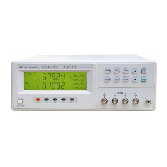
- Page 1 MANUAL DE USUARIO Medidor LCR modelo AD2817...
-
Page 2: Table Of Contents
Contenido CAPÍTULO 1 INTRODUCCIÓN GENERAL ............ 1 1.1 Prólogo ............................... 1 1.2 Condiciones de funcionamiento ....................... 3 Requisitos de alimentación ....................3 1.2.1 Temperatura de funcionamiento y humedad ..............3 1.2.2 Tiempo de calentamiento inicial..................3 1.2.3 Precauciones ........................3 1.2.4 1.3 Dimensiones y Peso ........................... - Page 3 Medida de los parámetros de los transformadores ........... 12 2.3.4 LCZ automático ....................... 12 2.3.5 Prueba de descarga ....................... 12 2.3.6 Memoria..........................12 2.3.7 Interfaces.......................... 13 2.3.8 CAPÍTULO 3 INTRODUCCIÓN A LOS PANELES ........14 3.1 Recorrido por el panel frontal ....................... 14 3.2 Recorrido por el panel trasero .......................
- Page 4 Funciones del bus GPIB ....................49 5.2.4 Formato de Datos ......................50 5.2.5 CAPÍTULO 6 INTERFAZ HANDLER ............. 51 6.1 Información general ........................51 6.2 Definición de las Señales ........................ 52 6.3 Características eléctricas ....................... 55 DC Isolated Outputs ....................... 55 6.3.1 Entrada DC aisolada ......................
-
Page 5: Capítulo 1 Introducción General
Manual de usuario AD2817 Capítulo 1 Introducción General Gracias por la compra de nuestro producto. El contenido del envío deberá ser el que está listado en la nota de entrega. Si el contenido no está completo, si detecta algún daño mecánico o defecto, o el instrumento no pasa los tests de arranque, por favor notifíquelo a nuestra empresa. - Page 6 Manual de usuario AD2817 la impedancia residual y otros errores. La función de corrección tiene dos métodos de funcionamiento. Con el primer método las correcciones de abierto y corto se realizan en todos los puntos de frecuencia, y con el segundo método, las correcciones se pueden efectuar en los puntos de frecuencia que se especifiquen.
-
Page 7: Condiciones De Funcionamiento
Manual de usuario AD2817 1.2 Condiciones de funcionamiento 1.2.1 Requisitos de alimentación Tensión: 220V (1±10%) Frecuencia: 50Hz/60Hz (1±5%) Consumo: <50VA 1.2.2 Temperatura de funcionamiento y humedad Temperatura: 0qC 40qC Humedad: <90%HR 1.2.3 Tiempo de calentamiento inicial Más de 20 minutos después de encender el equipo. 1.2.4 Precauciones No trabaje con el equipo en lugares polvorientos, con vibraciones, bajo luz solar, o en áreas en donde el aire sea corrosivo. -
Page 8: Compatibilidad Electromagnética
Manual de usuario AD2817 Para evitar descargas eléctricas, el chasis del instrumento debe de estar conectado a tierra a través del cable de alimentación. NO trabaje con el instrumento en una atmósfera explosiva. No haga funcionar al instrumento en presencia de gases o humos inflamables. EL funcionamiento de cualquier instrumento eléctrico en este tipo de entornos constituye un riesgo de la seguridad. - Page 9 Manual de usuario AD2817 BINn número bin COMP comparar capacidad serie equivalente capacidad paralela equivalente factor de disipación borrado del dispositivo DCHR descarga resistencia DC DELIM delimitador directo dispositivo bajo prueba externo fin de la medida final de la identificación resistencia serie equivalente FREQ frecuencia...
- Page 10 Manual de usuario AD2817 PARA B parámetro B porcentaje primario alto primario bajo factor de calidad resistencia, pare real de la impedancia resistencia DC para la medida de 2-hilos control remoto resistencia serie equivalente recomendación estándar resistencia paralelo equivalente SCPI Instrucciones estándar para instrumentos programables borrado del dispositivo seleccionado parámetro secundario...
-
Page 11: Capítulo 2 Especificaciones Básicas
AD2817 Operation Manual Capítulo 2 Especificaciones básicas 2.1 Funciones de medida 2.1.1 Parámetros de medida L: inductancia C: capacidad R: resistencia Z: impedancia X: reactancia D: disipación θ: ángulo de fase Q: factor de calidad DCR: resistencia DC Parámetros de transformadores: L2A: inductancia primaria L2B: inductancia secundaria N,1/N: relación de vueltas... -
Page 12: Rango
AD2817 Manual de usuario Cp=Cs/(1+D D=2SFCsRs=1/Q Rp=Rs(1+D Q=Xs/Rs, D=Rs/Xs, Xs=1/2πFCs=2πFLs Nota: Sufijo “s” significa serie; sufijo “p” significa paralelo. En el mundo real, los condensadores, resistencias e inductancia no son ideales, sino que son un combinación compleja en forma de conexiones serie o paralelo. El instrumento calcula los valores necesarios de acuerdo al circuito equivalente en serie o paralelo. -
Page 13: Retardo De La Medida
AD2817 Manual de usuario Manual: Cuando el disparo se ajusta al modo MANual, el instrumento realiza una única medida cada vez que se pulsa la tecla TRIGGER en el panel frontal. 2.1.6 Retardo de la medida Tiempo de espera después de que la medida se completa. Si se ha definido un borrado del interfaz HANDLER, la señal en el interfaz HANDLER se cancelará... -
Page 14: Señal De Prueba
AD2817 Manual de usuario 2.2 Señal de prueba 2.2.1 Frecuencia de la señal de prueba 10 frecuencias típicas: 50Hz, 60Hz, 100Hz, 120Hz, 1kHz, 10kHz, 20kHz, 40kHz, 50kHz, 100kHz. Precisión de frecuencia: 0.02% 2.2.2 Nivel de la señal de prueba 3 niveles de prueba: 0.1V, 0.3V, 1V Precisión: ±(10%×valor ajustado+2mV) 2.2.3 Impedancia de salida 30 ±5%, 100±5% (Impedancia fuente fijada 100 en el modo bias) -
Page 15: Función
AD2817 Manual de usuario 2.3 Función 2.3.1 Corrección Corrección en abierto (Open): Para eliminar los errores de medida debidos a las pérdidas parásitas en la entrada (C, G) del conjunto de pruebas. Corrección en corto (Short): Para eliminar los errores de medida debidos a las impedancias parásitas (L, R) del conjunto de pruebas. -
Page 16: Medida De Los Parámetros De Los Transformadores
AD2817 Manual de usuario 2.3.4 Medida de los parámetros de los transformadores El AD2817 dispone de la función de la medida de los parámetros básicos de un transformador mediante el modo de 2-hilos. Para la medida de los transformadores deberá usarse un conjunto de pruebas especial. El modo de medida de 2-hilos tiene menos precisión que el modo de medida de 4-hilos. -
Page 17: Interfaces
AD2817 Manual de usuario 2.3.8 Interfaces Interfaz IEEE488: También llamado interfaz GPIB es igual que el interfaz IEC625, pero con diferente sistema de enlaces. La comunicación tiene el formato SCPI y todas las instrucciones y datos en el BUS se envían en código ASCII. El interfaz soporta FETCH automático, y tiene las funciones de SH1, AH1, T5, L4, RL1, DC1, DT1, C0, y E1. -
Page 18: Capítulo 3 Introducción A Los Paneles
AD2817 Manual de usuario Capítulo 3 Introducción a los paneles 3.1 Recorrido por el panel frontal Figura 3-1 Panel Frontal Figura 3-2 Teclado Marca y modelo Nombre de la empresa y modelo del instrumento. Pantalla de 240×64 puntos matricial de cristal líquido (LCD) que muestra los resultados de las medidas, condiciones de las pruebas, etc. - Page 19 AD2817 Manual de usuario Interruptor on/off Interruptor encendido/apagado. En la posición “I” todas las tensiones están activas en el instrumento. En la posición “O” no se aplica ninguna tensión al instrumento. Teclado Permiten seleccionar las funciones mediante tres niveles: a) Funciones que se ejecutan pulsando directamente en las teclas PARA A: Seleccionar parámetros primarios PARA B: Seleccionar parámetros secundarios FREQ: Ajustar la frecuencia...
-
Page 20: Recorrido Por El Panel Trasero
AD2817 Manual de usuario Terminales “desconocidos” Estos terminales se usan para conectar un conjunto de pruebas de cuatro terminales o puntas de prueba para efectuar la medida del dispositivo bajo prueba. HD(H ): Drive de alta corriente HS(H ): Sensor de alto potencial LS(L ): Sensor de bajo potencial LD(L... -
Page 21: Descripción De La Pantalla
AD2817 Manual de usuario Terminal para la tensión de monitoreado del bias Equipado internamente con una tensión de bias ajustable de -5V +5V, el instrumento puede monitorear la tensión actual de bias mediante el medidor de bias DC. Ajuste de la tensión de bias El instrumento está... - Page 22 AD2817 Manual de usuario El AD2817 dispone de los siguientes parámetros primarios: L , Z, L2A, L2B. Visualización del resultado de la medida Muestra el resultado de la medida del dispositivo bajo prueba. Visualización de de la unidad de los parámetros primarios y secundarios Muestra la unidad de los parámetros primarios y secundarios.
-
Page 23: Capítulo 4 Instruciones De Manejo
AD2817 Manual de usuario 11) Indicador del comparador “COMP” on: La función del comparador está activa. “COMP” off: La función del comparador está desactivada. 12) Modo de visualización del parámetro primario Indica el modo actual de visualización del parámetro primario: “DIR”... -
Page 24: Configuración Del Parámetro Secundario
AD2817 Manual de usuario L2B. Pulse la tecla PARA A para cambiar el parámetro primario. O pulsePARA A, y a continuación▲ para cambiar de parámetro. Si se cambia un parámetro primario, el parámetro secundario también cambia: Ls, Lp —— Q; Cs, Cp ——... -
Page 25: Velocidad De Medida
AD2817 Manual de usuario 4.2.5 Velocidad de medida El AD2817 cuenta con tres velocidades de medida: F (rápida), M (media), S (lenta). Rápida: alrededor de 20 medidas por segundo. Media: alrededor de 10 medidas por segundo. Lenta: alrededor de 2 medidas por segundo. Pulse la tecla SPEED para cambiar la velocidad. -
Page 26: Corrección En Abierto
AD2817 Manual de usuario 100k 100k ∞ 100k Pulse la tecla RANGE para cambiar entre AUTO y HOLD. Pulse UP o DOWN para seleccionar manualmente el rango. El número del rango se mostrará en su zona correspondiente de la pantalla LCD. El AD2817 dispone también de la función de medida de resistencias en corriente continua DC. -
Page 27: Corrección En Corto
AD2817 Manual de usuario Figura 4-2 Corrección en abierto puntual 3. Seleccione para realizar una corrección puntual o una corrección de barrido mediante las teclas ▲ o ▼ , como se muestra en la figura 4-3. Figura 4-3 Corrección en abierto de barrido “SPOT”... -
Page 28: Modo De Visualización
AD2817 Manual de usuario 4.2.10 Modo de visualización Pulse SHIFT + DISP para cambiar el modo de visualización. El instrumento tiene tres modos de visualización: Visualización directa (DIR) --- El valor actual medido se muestra en la pantalla; Visualización de la desviación absoluta ( ) –... -
Page 29: Comparador
AD2817 Manual de usuario 4.2.11 Comparador Pulse SHIFT + COMP para activar o desactivar el comparador. Una vez que el comparador se desactiva, el símbolo indicador desaparece, la alarma no suena, los resultados de la comparación no produce ninguna salida a través del interfaz HANDLER , la señal de final de medida EOM no se produce, pero la señal IDX de desplazamiento AD y la entrada de disparo TRIG son todavía válidas. -
Page 30: Configuración De Las Medidas
AD2817 Manual de usuario 4.2.13 Configuración de las medidas Siga los siguientes pasos para acceder a la página de configuración de las medidas: 1. Pulse SHIFT en el modo de espera, y el símbolo “SHIFT” se mostrará en la esquina izquierda de la pantalla. - Page 31 AD2817 Manual de usuario GPIB. Este modo de disparo no puede configurarse desde el panel frontal. Debe de enviar la instrucción TRIGger:SOURce BUS vía GPIB o RS232C para definir el modo de disparo como BUS. Manual: Cuando el modo de disparo se configura como MANual, el instrumento efectúa una única medida cada vez que se pulsa la tecla TRIGGER en el panel frontal.
- Page 32 AD2817 Manual de usuario Figura 4-11 Configuración de la profundidad del filtro SRES Siga los siguientes pasos para seleccionar la resistencia fuente: Seleccione “SERS” mediante ▲ o ▼ , como se ve en la figura 4-12. b) Pulse para seleccionar “100 ” o “30 ”. Pulse ENTER o ESC para salir.
- Page 33 AD2817 Manual de usuario Figura 4-14 Selección de bias b) Pulse para seleccionar “+2DCV”, “-2DCV”, “EXDCV” o “OFF”. Pulse ENTER o ESC para salir. DCHR Siga los siguientes pasos para activar o desactivar el test de descarga: Seleccione “DCHR” mediante ▲ o ▼ , como muestra la figura 4-15. b) Pulse para seleccionar “ON”...
-
Page 34: Configuración De La Lista De Límites
AD2817 Manual de usuario 10) CABLE Siga los siguientes pasos para definir la longitud del cable: Seleccione “CABLE” mediante ▲ o ▼ , como muestra la figura 4-18. b) Pulse para seleccionar “om”, “1m” o “CUST”. Pulse ENTER o ESC para salir. Figura 4-18 ajuste de la longitud del cable 11) ZERO Siga los siguientes pasos para activar o desactivar la función de corrección:... - Page 35 AD2817 Manual de usuario Comparación del comparador y ordenación: Medida completa Parámetro primario mayor (PHI) Comparación parámetro primario Parámetro primario menor (PLO) Primero comparación con el BIN 1; Si falla, comparación con el BIN 2; No pasa bins FALLA BIN (Salida) Si falla, comparación con el BIN 3 Parámetro primario pasa algún bin AUX BIN off...
- Page 36 AD2817 Manual de usuario BIN2L: límite inferior del parámetro primario 2; BIN2H: límite superior del parámetro primario 2; BIN3L: límite inferior del parámetro primario 3; BIN3H: límite superior del parámetro primario 3; SEC L: límite inferior del parámetro secundario; SEC H: límite superior del parámetro primario secundario;...
- Page 37 AD2817 Manual de usuario a ser modificado. Pulse ▲ o ▼ para seleccionar el dato que necesita modificarse. d) Pulse para modificar el valor a 0,1,2,3,4,5,6,7,8,9; el primer valor podría ser también “-”. Si necesita reposicionar el punto decimal, pulse para seleccionar el punto decimal de forma que parpadee, y a continuación pulse para moverlo.
-
Page 38: Operaciones Con Archivos
AD2817 Manual de usuario Configuración de los límites de los parámetros superior e inferior (SEC L, SEC H) No existen valores nominales para los parámetros secundarios, por lo que sólo el límite absoluto de la no desviación puede ajustarse. En la pantalla de configuración de los límites, seleccione SEC L o SEC H mediante ▲ o ▼... -
Page 39: Configuración De Las Funciones Del Sistema
AD2817 Manual de usuario como se muestra en la figura 4-28. b) Pulse para seleccionar el archivo con un número entre 0-9. Si aparece “Y” significa que el archivo existe y podrá cargarse, mientras que si aparece “N” significa que el archivo no existe. - Page 40 AD2817 Manual de usuario KBEEP: sonido de la teclas activado/desactivado; KLOCK: bloqueo de las teclas activado/desactivado; SAVE: Guardado de la configuración del sistema Siga los siguientes pasos para acceder a la pantalla de configuración del sistema: En la pantalla de test, pulse SHIFT , y verá “SHIFT” en la esquina izquierda. Pulse SYSTEM para acceder a la pantalla de configuración del sistema, como ve en la figura 4-30.
- Page 41 AD2817 Manual de usuario Figura 4-31 Configuración de la dirección de comunicaciones GPIB BAUD El RS232C del AD2817 soporta 8 velocidades: 4800bps, 9600bps, 11520bps, 12800bps, 14400bps, 19200bps, 28800bps, y 38400bps. Siga los siguientes pasos para seleccionar la velocidad: En la pantalla de configuración del sistema, seleccione “BAUD” mediante ▲ o ▼ , como se muestra en la figura 4-32.
- Page 42 AD2817 Manual de usuario b) Pulse para seleccionar el modo de fetch. Pulse ENTER o ESC para salir. Figura 4-34 Modo de Fetch TRGEG Se dispone de dos tipos de flancos de disparo: RISE: La medida comienza con el flanco de subida del pulso de disparo; FALL: La medida comienza con el flanco de bajada del pulso de disparo.
- Page 43 AD2817 Manual de usuario Siga los siguientes pasos configurar la alarma: En la pantalla de configuración del sistema, seleccione “ALARM” mediante ▲ o ▼ , como se muestra en la figura 4-37. b) Pulse para seleccionar el modo de alarma. Pulse ENTER o ESC para salir.
- Page 44 AD2817 Manual de usuario Figura 4-39 Activar/desactivar el sonido de las teclas 11) KLOCK Siga los siguientes pasos para configurar el bloqueo de las teclas. En la pantalla de configuración del sistema, seleccione “KLOCK” mediante ▲ o ▼ , como se muestra en la figura 4-40. b) Pulse para activar o desactivar el bloqueo de las teclas.
-
Page 45: Capítulo 5 Control Remoto
AD2817 Manual de usuario Capítulo 5 Control Remoto El AD2817 dispone del interfaz serie RS232C y opcionalmente del intefaz paralelo GPIB. Ambos interfaces pueden usarse para controlar de forma remota al AD2817, pero no pueden usarse al mismo tiempo. Los dos interfaces comparten las mismas instrucciones de programación, pero tienen distinta configuración de hardware y diferentes protocolos de comunicaciones. -
Page 46: Comunicación Con Un Ordenador
AD2817 Manual de usuario se enumeran a continuación. Función Cód. Nº Pin Conector de 9 pines Transmitted Data Received Data Signal Ground Common El interfaz RS232 del AD2817 puede parecer diferente al estándar RS232C. La configuración de los pines en el conector es la siguiente. 5.1.2 Comunicación con un ordenador Diagrama de conexiones a un ordenador. - Page 47 AD2817 Manual de usuario Bits de parada 1 Bit Bit paridad Ninguno Fin de Secuencia NL (Código ASCII) Conector Protocolo de Software El controlador (PC) envía la instrucción usando el código ASCII con NL como carácter final. El AD2817 ejecuta la instrucción después de recibir el carácter NL. El carácter recibido por el AD2817 se enviará...
- Page 48 AD2817 Manual de usuario que se haya devuelto. Al mismo tiempo, el controlador (PC) deberá recibir el último carácter devuelto antes de recibir la respuesta a la consulta. Para algunas instrucciones que necesitan bastante tiempo para ejecutarse, como por ejemplo la instrucción Correction, el controlador (PC) deberá mantenerse a la espera para evitar que la siguiente instrucción se pierda mientras el AD2817 está...
- Page 49 AD2817 Manual de usuario int m,n; while( check_stat(PORT) & 256 ) read_port( PORT );/* lee datos hasta llegar al nulo */ for( m = 1000;m;m-- ) /* protocolo de comunicación: espera hasta que esté listo*/ { send_port( PORT,0xaa ); for( n = 100;n;n-- ) delay( 2 );...
- Page 50 AD2817 Manual de usuario c = read_port( PORT ); if( c == 0xcc ) continue;/*saltar los demás caracteres del protocolo de comunicación*/ if( c == '\n' ) break; *ps = c; ps++; *ps = 0; /* envía un carácter al puerto serie */ void send_port( int port,char c ) union REGS r;...
-
Page 51: Introducción Al Interfaz Gpib
AD2817 Manual de usuario int86( 0x14,&r,&r ); return r.x.ax; /* ax.7 muestra la operación serie, ax.8 muestra que está listo para recibir el puerto serie */ /* inicializa el puerto serie */ void port_init( int port,unsigned char code ) { union REGS r; r.x.dx = port;... - Page 52 AD2817 Manual de usuario Típica interconexión GPIB Nº 1 Figura 5-2 Interconexión GPIB típica Nº 1 Típica interconexión GPIB Nº 2 Figura 5-3 Interconexión GPIB típica Nº 2...
-
Page 53: Funciones Del Interfaz Gpib
AD2817 Manual de usuario 5.2.2 Funciones del interfaz GPIB Las funciones del GPIB del AD2817 se listan en la siguiente tabla. Código Función Complete Source Handshake capability Complete Acceptor Handshake capability Basic Talker; Talk-Only; unaddressed if MLA; no serial poll Basic Listener;... -
Page 54: Formato De Datos
AD2817 Manual de usuario de disparo debe de estar configurado en BUS antes de que se envía la instrucción de disparo. Esta instrucción es igual que la instrucción SCPI TRIG+FETCh? o la instrucción común *TRG. 5.2.5 Formato de Datos El AD2817 saca los resultados de las medidas mediante código ASCII a través del bus GPIB. MeasDisplay BinNo. -
Page 55: Capítulo 6 Interfaz Handler
AD2817 Manual de usuario Capítulo 6 Interfaz Handler 6.1 Información general El interfaz handler produce señales para indicar que la medida se ha completado, resultados de ordenación de los bin producidos por la función del comparador, y resultados Go/No-Go de la lista de barrido del comparador. El interfaz handler dispone también de una entrada para una señal externa de disparo. -
Page 56: Definición De Las Señales
AD2817 Manual de usuario 6.2 Definición de las Señales Pin No. Nombre Señal Descripción /BIN1 Decisiones de salida de la ordenación de los bin. /BIN2 Todas las señales de salida de los bin están opto-aisladas y /BIN3 de colector abierto. Sin conexión Sin conexión Sin conexión... - Page 57 AD2817 Manual de usuario señales aisladas, /BIN1-/BIN3, /AUX, /OUT, /PHI, /PLO, /SREJ. La configuración de los puentes internos deberá cambiarse cuando se use una tensión interna. Sin conexión /IDX Se produce la señal /IDX cuando se completa una medida analógica y el AD2817 queda listo para que el siguiente DUT se conecte a los terminales desconocidos.
- Page 58 AD2817 Manual de usuario T1 T2 /TRIG /IDX /EOM Result previous valid data valid data hold or clea one measurement period next period Time delay measurem calculating & display measurem triggger setup ent time comparing time ent delay Tiempo Valor Min. Valor Máx.
-
Page 59: Características Eléctricas
AD2817 Manual de usuario 6.3 Características eléctricas 6.3.1 Salidas DC aisladas Cada salida DC (pines 1 al 11, pines 19 al 21, pines 30 al 31) están aislados una salida opto acoplada de colector abierto. La tensión de salida de cada línea se ajusta mediante una resistencia de la placa del interfaz handler. - Page 60 AD2817 Manual de usuario Figura 6-5 Posición y configuración de los jumpers del interfaz HANDLER HANDLER interface board HANDLER interface connector 14,15 EXV2 internal +5V power J203 pull-up resistance 4.7k /IDX /EOM 32,33 COM2 J204 grounding *Posición por defecto Figura 6-6 Diagrama simplificado de las señales de salida de control HANDLER interface board HANDLER interface connector 27,28...
-
Page 61: Entrada Dc Aisolada
AD2817 Manual de usuario 6.3.2 Entrada DC aislada HANDLER interface board HANDLER interface connector Iternal +5V power 14,15 EXV2 J203 12,13 /TRIG 1.2k 2.2k trigger resistance with J205 limit current 32,33 COM2 J204 grounding * Posición por defecto Figura 6-8 Diagrama simplificado de las señales de entrada de disparo del interfaz HANDLER internal +5V power EXV2... -
Page 62: Capítulo 7 Embalaje Y Garantía
AD2817 Manual de usuario Capítulo 7 Embalaje y Garantía 7.1 Embalaje El contenido del embalaje es el siguiente: Descripción Cantidad AD2817 LCR instrumento AD26005 conjunto de pruebas AD26011 cable para pruebas Kelvin AD26010 placa para cortos AD26038 conjunto de pruebas para transformadores Cable de alimentación AC Fusible 1A Manual de usuario... - Page 63 AD2817 Manual de usuario OPERATION MANUAL AD2817C LCR Meter...
- Page 64 AD2817 Manual de usuario Content CHAPTER 1 GENERAL INTRODUCTION..................1 1.1 Foreword ..........................1 1.2 Operating Conditions ......................2 1.2.1 Power requirements ....................2 1.2.2 Opearing temperature and humidity ................2 1.2.3 Warm-up time ......................3 1.2.4 Notices ........................3 1.3 Dimensions &...
- Page 65 AD2817 Manual de usuario CHAPTER 4 OPERATION INSTRUCTIONS ................20 4.1 Turning on the Instrument ....................20 4.2 Function Operations ......................20 4.2.1 Primray parameter setup ................... 20 4.2.2 Secondary parameter setup ..................20 4.2.3 Frequency setup ....................... 21 4.2.4 Signal voltage ......................
-
Page 66: Chapter 1 General Introduction
AD2817C is a precision LCR meter with high accuracy, good stability, and wide measurement range. Controlled by a 16 bits MPU, AD2817C can be used for evaluating LCR components, materials and semiconductor devices over a wide range of frequencies (50 Hz to 100 kHz) and test signal levels (0.1V, 0.3V, 1V). -
Page 67: Operating Conditions
AD2817C has the file function to store the set parameters, limit parameters and list sweep parameters as a file in the internal nonvolatile memory, so that the setups can be easily reloaded, and the defult file will be automatically reloaded when AD2817C is turned on. -
Page 68: Warm-Up Time
AD2817C Operation Manual Humidity: <90%RH 1.2.3 Warm-up time More than 20 minutes after the instrument is turned on. 1.2.4 Notices Please do not operate the instrument in the place that is vibrative, dusty, under direct sunlight, or where there is corrosive air. -
Page 69: Electromagnetic Compatibility
AD2817C Operation Manual disconnect power and discharge circuits before touching them. DO NOT attempt service or adjustment alone Do not attempt internal service or adjustment unless another person, capable of rendering first aid and resuscitation, is present. DO NOT substitute parts or modify instrument Because of the danger of introducing additional hazards, do not install substitute parts or perform unauthorized modifications to the instrument. - Page 70 AD2817C Operation Manual end or identify equivalent serial resistance FREQ frequency go to local group execution trigger GPIB general-purpose interface Bus Handler interface index interface clear internal KBEEP kep beep KLOCK key lock primary inductance by 2-wire measurement secondary inductance by 2-wire measurement...
- Page 71 AD2817C Operation Manual secondary parameter surface mount devices SREJ secondary reject SRES source resistor TRGEG trigger edge TRIG trigger reactance, imaginary part of impedance impedance phase angle θ 4-terminal pair...
-
Page 72: Chapter 2 Basic Specifications
AD2817C Operation Manual Chapter 2 Basic Specifications 2.4 Measurement Functions 2.1.1 Measurement parameters L: inductance C: capacitance R: resistance Z: impedance X: reactance D: dissipation Q: quality factor θ: phase angle DCR: DC resistance Transformer parameters: L2A: primary inductance L2B: secondary inductance... -
Page 73: Range
When the trigger mode is set to BUS trigger mode, the instrument performs a single measurement every time the *TRG common command is sent to AD2817C via GPIB. The BUS trigger mode cannot be set on the front panel. Send the TRIGger:SOURce BUS command via GPIB or RS232C to set the trigger mode to the BUS trigger mode. -
Page 74: Measuremetn Delay
AD2817C Operation Manual a single measurement every time when TRIGGER key on the front panel is pressed. 2.1.6 Measuremetn delay Waiting time after measurement completes. If HANDLER interface clear has been set, signal on HANDLER interface will be cancelled after delay. -
Page 75: Test Signal
AD2817C Operation Manual 2.5 Test Signal 2.2.1 Test singal frequency 10 typical frequencies: 50Hz, 60Hz, 100Hz, 120Hz, 1kHz, 10kHz, 20kHz, 40kHz, 50kHz, 100kHz. Frequency accuracy: 0.02% 2.2.2 Test signal level 3 test levels: 0.1V, 0.3V, 1V Accuracy: (10% set value+2mV) 2.2.3 Output impedance... -
Page 76: Function
Percentage deviation between measured result and nominal value is displayed. 2.3.4 Transformer parameter measurement AD2817C has the function of measuring basic parameters of single transformer through 2-wire mode. And special test fixture should be used at the time of transformer... -
Page 77: Automatic Lcz
AD2817C Operation Manual 2-wire measurement mode has less accuracy than 4-wire measurement mode. 2.3.5 Automatic LCZ The instrument automatically selects L, C, Z and equivalent mode according to impedance characteristics of the device under test, to automatically recogonize unkown and mixing components. - Page 78 AD2817C Operation Manual RS232C interface: It uses standard minimum subclass of RS232C and doesn’t support hardware connection. The interface has transfer baud rate: 4800bps, 9600bps, 11520bps, 12800bps, 14400bps, 19200bps, 28800bps, and 38400bps, signal logic level of 8V and maximum transfer distance of 15m. The communication command is in the format of SCPI, and all commands and data on BUS are sent in ASCII code.
-
Page 79: Chapter 3 Panel Introductions
AD2817C Operation Manual Chapter 3 Panel Introductions 3.4 A Tour of Front Panel Figure 3-1 Front panel overview Figure 3-2 Softkeys Brand and Model The registered brand of our company and model of the instrument are printed. 240×64 dot-matrix Liquid Crystal Display (LCD) displays measurement results, test conditions, etc. - Page 80 AD2817C Operation Manual Power on/off switch. In the “I” position all operating voltages are applied to the instrument. In the “O” position NO operating voltages are applied to the instrument. Softkeys They have functions of three levels: a) Functions by directly pressing softkeys...
-
Page 81: A Tour Of Rear Panel
AD2817C Operation Manual These are the UNKNOWN Terminals used to connect a four-terminal pair test fixture or test leads for measuring the device under test. HD(H ): High current drive HS(H ): High potential sense LS(L ): Low potential sense... -
Page 82: Display Description
LINE input receptacle AC power cord receptacle. Fuse holder Fuse holder for AD2817C line fuse, 220Vac, 1A. Name plate Name plate is used to provide the information of date, model, lot number and manufacturer etc. Grounding If the power cord doesn’t ground or isn’t reliably grounding, please connect grounding line! - Page 83 Secondary parameter indicator It indicates secondary parameters of the currently measured component. AD2817C has the following secondary parameters: θ° (angle), θr (radian), R, X, DCR, Q, D, N, 1/N, M, R2. 16) Bias indicator “BIAS” on: Bias function is turned on.
- Page 84 AD2817C Operation Manual “DIR” on: direct mode. “ ” on: absolute deviation mode. “%” on: percentage deviation mode. 12) RMT RMT means the instrument is at the status of remote communication when only LOCAL key can be operated on panel.
-
Page 85: Chapter 4 Operation Instructions
L2A, L2B —— N 4.2.2 Secondary parameter setup AD2817C has the following common secondary parameters: θ° (angle), θr (radian), R, X, Q, AD2817C also has the function of measuring DC resistance and transformer parametersw. Secondary parameters differ with parimary parameters:... -
Page 86: Frequency Setup
TRIGGER key once. 4.2.7 Range setup AD2817C totally has 9 ranges: 10 , 30 , 100 , 300 , 1k , 3k , 10k , 30k , 100k. Please select range accoding to the impedance of the device under test. -
Page 87: Open Correction
4.2.8 Open correction Press SHIFT + OPEN to enter open correction menu. AD2817C’s open correction function can eliminate the effect of test cable, test fixture and stray admittance in parallel with the device under test, such as stray capacitance. Perform the following steps to perform open correction: 1. -
Page 88: Short Correction
4.2.9 Short correction Press SHIFT + SHORT to enter short correction menu. AD2817C’s open correction can eliminate the effect of test cable, test fixture and stray impedance in series with the device under test, such as lead resistance or lead inductance. -
Page 89: Display Mode
AD2817C Operation Manual 5. Press ENTER key to start correction. 4.2.10 Display mode Press SHIFT + DISP to change display mode. The instrument has three display modes: Direct display (DIR) --- Actual measured value is displayed; Absolute deviation display ( ) –... -
Page 90: Bias
AD2817C Operation Manual 3. Press SHIFT key, and “SHIFT” at left corner is on. 4. Press COMP key, “COMP” is displayed on LCD, which means comparison function has been turned on, as shown in Figure 4-7. Figure 4-7 Comparison function on/off 4.2.12 Bias... - Page 91 When the trigger mode is set to BUS trigger mode, the instrument performs a single measurement every time the *TRG common command is sent to AD2817C via GPIB. The BUS trigger mode cannot be set on the front panel. Send the TRIGger:SOURce BUS command via GPIB or RS232C to set the trigger mode to the BUS trigger mode.
- Page 92 Figure 4-12 Resistance selection 10) BIASM (bias mode) 11) BIAS (bias source) AD2817C has internal bias voltage of -5V +5V and internal bias current of -50mA +50mA. Before using bias function, bias mode should be selected: d) Select “BIASM” through...
- Page 93 Press ENTER key or ESC key to exit. AD2817C has the following bias sources to be selected: OFF: oV bias source +2DCV: internal fixed +2V bias source -2DCV: internal fixed -2V bias source...
- Page 94 AD2817C Operation Manual 13) RANGE Perform the following steps to set different range types: key, as shown in Figure4-16. Select “RANGE” through d) Press ▲ or ▼ key to select “LCR” or “DCR”. e) Press ENTER key or ESC key to exit.
-
Page 95: Limit List Setup
AD2817C Operation Manual Figure 4-19 Correction switch 4.2.14 Limit list setup AD2817C can set 3-bin limit data of primary parameter, and 1-bin limit data of secondary parameter. The comparison result can be indicated through sorting indicators: OUT: fail; pass bin 1;... - Page 96 AD2817C Operation Manual Measurement completes Higher primary parameter (PHI) Primary parameter comparison Lower primary parameter (PLO) BIN 1 comparison first; If fails, BIN 2 comparison; No pass bins FAIL BIN (OUT) If fails, BIN 3 comparison Primary parameter passes some bin...
- Page 97 AD2817C Operation Manual BIN3L: low limit of primary parameter 3; BIN3H: high limit of primary parameter 3; SEC L: low limit of secondary parameter; SEC H: high limit of secondary parameter; At limit setup page, press key to select item, press ▲ or ▼...
- Page 98 AD2817C Operation Manual point to twinkle, then press ▲ or ▼ key to move it. If multiple needs modifying, press key to select the unit and multiple to twinkle, then press ▲ or ▼ key to modify multiple. g) After setting, press ENTER key to ensure the modification, or ESC key to cancel it.
-
Page 99: File Operation Function
AD2817C Operation Manual Figure 4-26 Limit setup of secondary parameter 4.2.15 File operation function Perform the following steps to enter file operation page: At test status, press SHIFT key, and “SHIFT” at left corner is on. Press FILE key to enter file operation page, and the instrument first displays currently-used file No., (if no file is loaded, the default setup of file No. -
Page 100: System Function Setup
AD2817C Operation Manual Figure 4-28 Loading file ERASE Perform the following steps to erase file: Select “ERASE” at file operation page through key, as shown in Figure4-29. b) Press ▲ or ▼ key to select erasing file No. Displayed “Y” means the file has existed, and “N”... - Page 101 ESC key to exit. Figure 4-31 Communication address setup BAUD AD2817C’s RS232C supports 8 common baud rates: 4800bps, 9600bps, 11520bps, 12800bps, 14400bps, 19200bps, 28800bps, and 38400bps. Perform the following steps to select baud rate: At system setup page, select “BAUD” through key, as shown in Figure 4-32.
- Page 102 AD2817C Operation Manual Figure 4-32 Baud rate setup DELIM AD2817C supports to send several common ending symbols: line change symbol (ASCII ode 100); enter symbol (ASCII code 13); CR+LF: enter to change line Perform the following steps to select: At system setup page, select “DELIM” through key, as shown in Figure 4-33.
- Page 103 ▲ or ▼ key to select HOLD or CLEAR. Press ENTER key or ESC key to exit. Figure 4-36 HANDLER interface’s signal hold ALARM AD2817C provides alarm function for sorting result. OFF: alarm off; NOGO: alarm at fail (no good);...
- Page 104 AD2817C Operation Manual There are 6 sounds available: LO.SHT: low and short; LO.LON: low and long; LO.TWO: two short and low; HI.SHT: high and short; HI.LON: high and long; HI.TWO: two short and high Perform the following steps to set sound: At system setup page, select “SOUND”...
- Page 105 AD2817C Operation Manual Figure 4-40 Keylock on/off setup After keylock is set, function keys on panel can’t be available. Press SHIFT, then SYSTEM to enter “KLOCK” operation, press ▲ or ▼ to unlock. 12) SAVE Perform the following steps to save setups: Select “SAVE”...
-
Page 106: Chapter 5 Remote Control
AD2817C has the RS232C serial interface and the parallel GPIB (optional) interface. Both interfaces can be used to remotely control AD2817C, but they can not be used at the same time. The two interfaces share the same program commands, but they have different hardware configurations and different communication protocols. -
Page 107: Communication With A Computer
9 Pin Connector Pin Number Transmitted Data Received Data Signal Ground Common AD2817C’s RS232 interface may be different with the standard RS232C. The pin configuration is shown as follows. 5.1.2 Communication with a computer Diagram of connection to a controller. DTR(4) - Page 108 AD2817C executes the command after the end character NL is received. 10) The character received by AD2817C will be sent back to the controller again. The controller will not send the next character until the last return character is received correctively from AD2817C.
- Page 109 16) For some commands that will take a long time to execute, for example Correction command, the controller should keep waiting to avoid the next command being lost when AD2817C is executing the former command. Sample Program for Serial Interface The following is a C language sample program under DOS environment.
- Page 110 & 256 ) { c = read_port( PORT ); break; if( n ) break;/*AD2817C/C not ready for receive*/ if( c != 0xcc )/*check receive*/ { printf( "\nE10:Serial Port HandShake Failure!" ); exit(1); /*handshake success,begin send string */ for( ;*ps;...
- Page 111 AD2817C Operation Manual if( c == '\n' ) break; *ps = c; ps++; *ps = 0; /* send a character to serial port */ void send_port( int port,char c ) union REGS r; r.x.dx = port; /* serial port */ r.h.ah = 1;...
-
Page 112: Gpib Interface Introduction
AD2817C Operation Manual { union REGS r; r.x.dx = port; /* serial port */ r.h.ah = 0; /* int14 function0:initial serial port */ r.h.al = code; /* initialization code */ int86( 0x14,&r,&r ); 5.3 GPIB Interface Introduction 5.2.1 GPIB connection When configuring a GPIB system, the following restrictions must be adhered to. - Page 113 AD2817C Operation Manual Typical GPIB System Interconnection-1 Figure 5-2 Typical GPIB System Interconnection-1 Typical GPIB System Interconnection-2 Figure 5-3 Typical GPIB System Interconnection-2...
-
Page 114: Gpib Interface Functions
AD2817C's GPIB address is stored in non-volatile memory and can be set to any address from 0 to 30 by front panel key entry in the System Config page. When AD2817C is shipped from the factory, the default GPIB address is 8. For more information, refer to “... -
Page 115: Data Format
AD2817C Operation Manual 5.2.5 Data format AD2817C outputs the measurement results using the ASCII via the GPIB bus. The Format 1 MeasDisplay BinNo. Disp Bin Count is used by page, page and page, while Format 2 is List Sweep used by page. -
Page 116: Chapter 6 Handler Interface
The handler interface also has an input for an external trigger signal. Using these signals, AD2817C can easily be combined with a component handler and a system controller to fully automate component testing, sorting, and quality control data processing to increase production efficiency. - Page 117 AD2817C Operation Manual No Connection No Connection /OUT Bin sorting judgments. /AUX All bin sorting signal outputs are opto-isolated open collector. /TRIG External Trigger: /TRIG AD2817A is triggered on the rising edge of a pulse applied to this pin when the trigger mode is set to EXT mode.
- Page 118 AD2817C Operation Manual COM2 COM1 Common for EXTV1 COM1 COM1 Table 6-2 Pin assignments for comparator function PHI OUT Primary BIN 1 Parameter BIN 2 SREJ AUX SREJ AUX BIN 3 PLO OUT Secondary Parameter Figure 6-1 /PHI, /PLO, /SREJ signal’s area example...
-
Page 119: Electrical Characteristics
AD2817C Operation Manual T1 T2 /TRIG /IDX /EOM Result previous valid data valid data hold or clea one measurement period next period Time delay measurem calculating & display measurem triggger setup ent time comparing time ent delay Time Min. value Max. - Page 120 AD2817C Operation Manual the internally supplied voltage (+5V), or to an externally applied voltage ( EXTV: +5V to +24V) by setting jumpers. The electrical characteristics of the DC isolated outputs are divided into two types (See Table 6-4). Since the power source for the Comparison Output and Control Output signals are different, two circuit commons (COM1, COM2) are made available.
- Page 121 AD2817C Operation Manual HANDLER interface board HANDLER interface connector 14,15 EXV2 internal +5V power J203 pull-up resistance 4.7k /IDX /EOM 32,33 COM2 J204 grounding *Defult Jump wire position Figure 6-6 Simplified diagram of the control output signals HANDLER interface board...
-
Page 122: Dc Isolated Input
AD2817C Operation Manual 6.3.2 DC Isolated Input HANDLER interface board HANDLER interface connector Iternal +5V power 14,15 EXV2 J203 12,13 /TRIG 1.2k 2.2k trigger resistance with J205 limit current 32,33 COM2 J204 grounding * Defult Jump wire position Figure 6-8 Simplified digram of HANDLER interface’s trigger input signals... -
Page 123: Chapter 7 Packing & Warranty
Chapter 7 Packing & Warranty 7.1 Packing The contents are listed as follows: Description Quantity 12. AD2817C LCR Meter 13. AD26005 Test Fixture 14. AD26011 Kelvin Test Cable 15. AD26010 Shorting Plate 16. AD26038 Transformer Test Fixture 17. Three-Wire Power Cord 18.
Need help?
Do you have a question about the AD2817C and is the answer not in the manual?
Questions and answers