
Subscribe to Our Youtube Channel
Related Manuals for Icom MR-1210RII


Summary of Contents for Icom MR-1210RII
- Page 1 INSTRUCTION MANUAL MARINE RADAR MR-1210R™ (Radome type) MR-1210T™ (Open array type: 4 kW) MR-1210T (Open array type: 6 kW)
-
Page 2: Supplied Accessories
SYSTEM COMPONENTS MODEL NAME DISPLAY UNIT SCANNER UNIT MR-1210RII EX-2714 (Radome type) MR-1210TII 12.1-inch Color LCD EX-2780 (Open array type: 4 kW) MR-1210TIII EX-2780 (Open array type: 6 kW) SUPPLIED ACCESSORIES • EX-2714 (Radome type unit) • 12.1-inch Color LCD display unit... -
Page 3: Important
The MR-1210RII/MR-1210TII/MR-1210TIII are supplemental aids to navigation and are not intended to be a substitute for accurate and current nautical charts. Thank you for choosing this Icom product. The MR- BE CAREFUL! 1210RII, MR-1210TII, MR-1210TIII marine ra are designed and built with Icom's state of the art... -
Page 4: Precautions
PRECAUTIONS However, if it is dropped, splash resistance cannot be For Display unit: guaranteed because of possible damage to the case R WARNING! NEVER let metal, wire or other or the waterproof seals. objects contact the inside of the display unit, or make incorrect contact with connectors on the rear panel. -
Page 5: Table Of Contents
TABLE OF CONTENTS ■ Plotting marks ............33 SYSTEM COMPONENTS .......... i ■ Course and speed vector .........33 SUPPLIED ACCESSORIES ........i ■ Plots (ATA) ...............33 IMPORTANT ...............ii FEATURES ..............ii 7. AIS OPERATION ......... 34–38 EXPLICIT DEFINITIONS ..........ii ■ AIS (Automatic Identification System) ......34 PRECAUTIONS ............iii ■... -
Page 6: Panel Description
PANEL DESCRIPTION ■ Front panel GAIN MARINE RADAR MR-1210 SAVE GAIN RAIN SAVE AUTO RAIN ENTER CLEAR TRAILS MENU MODE ENTER CLEAR OFF CENT EBL1 EBL2 VRM1 VRM2 TRAILS ZOOM BRILL MENU MODE HL OFF OFF CENT EBL1 EBL2 VRM1 VRM2 ZOOM BRILL... - Page 7 PANEL DESCRIPTION i OFF CENTER FUNCTION [OFF CENT]/[ ] (p. 19) !4 EBL1 (VRM1) KEY [EBL1 (VRM1)]/ ] (pp. 26–28) Simultaneously push [MENU]/[ ] and [MODE]/ ] to turn the OFF CENTER function ON or OFF. ➥ Push to display the EBL1 (Electronic Bearing •...
-
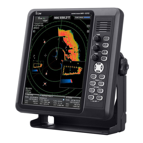
Page 8: Screen
PANEL DESCRIPTION ■ Screen This Display example is set to Wide in the “PPI Area” item of the Display menu. q HEADING INDICATOR t VECTOR INDICATOR (p. 7) Shows the heading readout. ➥ Shows the ATA, AIS and Own vector type. •... - Page 9 PANEL DESCRIPTION !0 LONG PULSE ICON (p. 20) !9 EBL1 (pp. 26–28) @0 EBL2 (pp. 26–28) Displayed when the long pulse is used. Used to measure bearing. !1 NORTH MARK When a target is selected, the EBL/VRM1 readouts The north mark indicates the true north direction. (!5 ) or the EBL/VRM2 readouts (!8 ) display its bear- ing.
-
Page 10: Menu Screen
MENU SCREEN ■ Entering Menu screen D Heading Line Brill Sets the Heading line brilliance to 1 (dark), 2 (normal), or 3 (bright). D Ring Brill* • OFF: The fixed range rings are not displayed, and the scale is displayed in dark, the same as 1 (dark). -
Page 11: Trail Menu
MENU SCREEN ■ Trail menu ■ Display menu D Reset D Own Vector q Push [ENTER]/[ • OFF: Does not display your own ship’s vector. • The dialog box “Sure?” is displayed. • ON: Displays your own ship’s vector. w Push [ENTER]/[ ] again to clear the trail. -
Page 12: Target Menu
MENU SCREEN ■ Target menu ■ ATA menu D Vector Mode D Function • True: Selects the true vector mode. • OFF: Turns OFF the ATA (Automatic Tracking Aid) • Relative: Selects the relative vector mode. function. • ON: Turns ON the ATA function. D Vector time D Track Sets the vector length (time) to 30 seconds, 1 minute,... -
Page 13: Ais Menu
MENU SCREEN ■ AIS menu D New Target Warning Sets whether or not to alert when the Auto Activate function automatically turns the sleeping AIS target into an activated target. • OFF: Does not give a warning when the Auto Acti- vate function activates the target. - Page 14 MENU SCREEN ■ AIS menu (Continued) The criteria to become a Lost target • Class A/B Nominal reporting Lost target maximum Lost target Nominal re- interval Class B * interval Class B * maximum Vessel type porting interval interval Class A Class A CS * SO *...
-
Page 15: Video Menu
MENU SCREEN ■ Video menu D Pulse Width • SP: Sets the pulse width to narrow. • LP: Sets the pulse width to wide. “ ” is displayed in the upper left corner of the screen. D SEA Curve • The SEA knob can be used to fine tune the sea clut- ter of the display after one of four main levels are se- lected, depending on the sea conditions. - Page 16 MENU SCREEN ■ System menu (Continued) D Zone Alarm1 D Bearing Reference D Zone Alarm2 Sets the direction for the EBL (Electronic Bearing Line) or cursor. Sets the Zone Alarm1 and Zone Alarm2 settings. • True: True or magnetic direction •...
-
Page 17: Initial Menu
MENU SCREEN ■ Initial menu D TX Inhibit Selects whether or not to use the TX inhibit. D TX Inhibit Start • 0 to 359°: Enters the start point of the TX inhibit area. D TX Inhibit Angle • 1 to 90°: Enters the TX inhibit area. -
Page 18: Ais List Menu
MENU SCREEN ■ AIS List menu ■ Initial menu (Continued) D Setting Reset Resets the settings in the Menu screen other than the settings in the Initial menu. You can reset only in the Standby mode. (p. 58) q Push [ENTER]/[ •... -
Page 19: Ais Own Menu
MENU SCREEN ■ AIS Own menu • The display is automatically updated by new status. • Push [ENTER]/[ ] to pause the display update. Push again to restart. Displays own AIS information. • Push [p] or [q] to scroll the window. e Push [CLEAR]/[ ] to close the window. -
Page 20: Basic Operation
BASIC OPERATION ■ Checking the installation D Checklist Before turning ON the power, be sure all the connec- q The four bolts securing the scanner unit must be tions are complete. The checklist to the right may be firmly tightened. helpful for necessary confirmation. -
Page 21: Basic Operation
BASIC OPERATION ■ Basic operation q Turn ON the power. w Push [TX (SAVE)]/[ ] on the Standby screen GAIN after the Warm-up is completed. • See “Turning power ON/OFF” on page 15. e Push [+]/[ ] one or more times to select the SAVE maximum display range. -
Page 22: Brilliance/Color Adjustment
BASIC OPERATION ■ Brilliance/Color adjustment D Adjusting the Display Brilliance D Selecting the Display color The intensity of the screen can be adjusted. When you Three display colors can be memorized and selected require continuous operation, but not constant view- between the Day, Night, and User settings. -
Page 23: Rain Function
BASIC OPERATION The following are typical basic operation examples that may hinder radar reception (sea clutter, precipitation in- terference and echoes from other radar). ■ SEA function This function serves to eliminate echoes from waves at close range. Reduce the receiver gain for close objects within a radius of approximately 8 NM to eliminate sea clutter. -
Page 24: Ir Function
BASIC OPERATION ■ OFF CENTER function The scanning area can be shifted in a desired direction and can be partially enlarged. This is useful when the Head-up screen is selected, and you want to enlarge the bow direction display, or the center of the screen shifts in the direction of the intersection. -
Page 25: Zoom Function
BASIC OPERATION ■ Zoom function The Zoom function expands the target to two times normal size. q Push [p], [q], [t], or [u] to move the cursor to the desired target. w Push [EBL1(VRM1)]/[ ] and [EBL2(VRM2)]/ ] simultaneously to toggle between the Zoom function ON and OFF. -
Page 26: Trail Function
BASIC OPERATION ■ Trail function The trail function memorizes echoes continuously or D Customizing the trail settings at constant intervals. This is useful for watching other You can customize the trail settings in the Trail menu in vessels’ tracks, approximate relative speed, and so on. the Menu screen. -
Page 27: Power Save Function
BASIC OPERATION ■ Power save function The power save function conserves the boat’s bat- tery power by pausing the transmission. The standby (pausing) times are selectable (rotation number is fixed to 10). For example, when 1 minute is selected, the scanner rotates 10 revolutions;... -
Page 28: Ship Speed Indication
BASIC OPERATION ■ Ship speed indication (MENU > Initial > Speed Unit) When the ship speed data in NMEA 0183 format is ap- plied, the radar can display the ship speed. q Push [MENU]/[ ], and then push [t] or [u] to select the Initial menu. -
Page 29: Bearing Setting
BASIC OPERATION ■ Bearing setting (MENU > System > Bearing Mode) The radar bearing interface accepts NMEA, N+1, AUX, T: True north or COG data format and the bearing can use a mag- M: Magnetic north netic or true north type. When a true north type bear- ing is used, the variation from magnetic north can be adjusted on 0.1˚... -
Page 30: Distance And Direction Measurements
DISTANCE AND DIRECTION MEASUREMENTS ■ Distance measurement Various way to measure the distance are provided with this radar. • The distance unit, nautical miles (NM), kilometers (kn), or miles (SM) is selected in the Initial menu of the Menu screen (p. 12). TYPE DESCRIPTION Displays fixed rings. - Page 31 DISTANCE AND DIRECTION MEASUREMENTS D Using the Parallel index lines D Using the variable range marker q Simultaneously hold down [EBL1(VRM1)]/ q Push [EBL1 (VRM1)]/[ ] to display the ] and [EBL2(VRM2)]/[ VRM1 and EBL1; then push [p] or [q] to set the for 1 second to display the Parallel index lines.
-
Page 32: Bearing And Distance Measurement
DISTANCE AND DIRECTION MEASUREMENTS ■ Bearing and Distance measurement This radar has two Electronic Bearing Lines (EBL) to indicate the target direction from your ship or a target. D Using both the EBL and VRM EBL1 q Push [p], [q], [t], or [u] to move the cursor onto the desired target. - Page 33 DISTANCE AND DIRECTION MEASUREMENTS D Measuring the relative speed and course of a target q Simultaneously push [ENTER]/[ ] and [CLEAR]/ ] to turn ON the Trail function, and then the trail extends until it reaches to the preset trail time. (pp. 6, 21) •...
-
Page 34: Alarm Function
ALARM FUNCTION The unit has an alarm function to protect your vessel from collisions. If other vessels, islands or other obstructions come into the preset alarm zone, the function alerts you with an alarm. You can set the desired range and bearing for up to two alarm zones. -
Page 35: Setting Zone Alarm Type
ALARM FUNCTION ■ Setting Zone alarm type A zone alarm sounds when the target comes into the (MENU > System > Zone Alarm1) zone, or when the target goes out of the zone. (p. 11) (MENU > System > Zone Alarm2) q Push [MENU]/[ ], and then push [t] or [u] to Target (other ship, and so on) -
Page 36: Ata Operation
ATA OPERATION ■ ATA (Automatic Tracking Aid) By automatically tracking the target chosen with the cursor key, the closest point of approach (CPA) and the time to closest point of approach (TCPA) limit of your vessel and a target are calculated. ATA function is designed to sound an alarm when the CPA and TCPA fall below a set value (the approach watch area). -
Page 37: Related Settings
ATA OPERATION ■ Related settings D Target menu You can change the target settings for ATA operation. The settings of the Target menu are commonly used for the ATA and AIS operations. See page 7 for the Target menu details. These are the Target menu items and their default set- tings. -
Page 38: Plotting Marks
ATA OPERATION ■ ATA operation (Continued) D All Clear Target (MENU > ATA > All Clear Target) Releases all of the ATA targets at the same time. q Push [MENU]/[ ], and then push [t] or [u] to select the ATA menu. w Push [p] or [q] to select the “All Clear Target”... -
Page 39: Ais Operation
AIS OPERATION ■ AIS (Automatic Identification System) AIS is an acronym for “Automatic Identification System.” An AIS transponder is a short range data radio unit, used primarily for collision-risk management and navigation safety. It automatically transmits and receives vessel information such as the vessel name, MMSI code, vessel type, position data, speed, course, destination and more. -
Page 40: Related Settings
AIS OPERATION ■ AIS Setting (Continued) D Safety Message D Auto Activate - Angle Sets whether or not to display the message when the Sets the angle to automatically turn the sleeping AIS safety message is received. target into an activated target. •... -
Page 41: Description Of The Ais Display
AIS OPERATION ■ Description of the AIS display AIS target The AIS targets are displayed with the icons described AIS target AIS icon below. Icon Description Vessel The tip of the target triangle automatically points in the direction it’s heading. Base Station Search and Rescue (SAR) Aids to Navigation (AtoN) -
Page 42: Ais Operation
AIS OPERATION ■ AIS operation D Operation Select a target whose information you want to display on the screen. • AIS information box Turn ON the AIS display and set its settings. (pp. 34, MMSI number AIS classes/Target type Speed q Push [p], [q], [t] or [u] to move the “+”... -
Page 43: Status Of The Vessel Icon
AIS OPERATION ■ Status of the vessel icon There are 5 kinds of target vessel status. Sleeping target: The AIS signal has been updated (received), but the distance from your vessel is far, or you set it as ‘sleeping.’ The target is displayed as just a triangle without a heading or vector line. -
Page 44: Basic Radar Theory
BASIC RADAR THEORY Radar uses a form of electromagnetic radiation that can be reflected off a large vessel, bridge, or other metal ob- jects that are in proximity. Because of this property, unwanted reflections off some objects may cause false echoes to appear on the screen where in fact no actual targets exist. -
Page 45: Multiple Echoes
BASIC RADAR THEORY ■ Multiple echoes Multiple echoes may appear when a short-range Multiple echoes will appear beyond the target’s true and strong echo is received from a vessel, bridge, or echo point on the same bearing of a large target. They breakwater. -
Page 46: Blind And Shadow Sectors
BASIC RADAR THEORY ■ Blind and Shadow sectors Blind or Shadow sectors may exist because of obstruc- When tall and massive targets such as a large island tions such as masts, derricks or other metal objects. are located at close range also shadowed without pro- An obstruction may throw either a complete or partial ducing any echoes. -
Page 47: Installation And Connections
INSTALLATION AND CONNECTIONS ■ Connecting the units Display unit Power supply 10.2 to 42 V DC Black: _ Red: Supplied Scanner unit NEVER connect anything other than the supplied Scanner unit. NOTE: Use the ter mi- nals as shown below for Ground the cable connections. -
Page 48: Installing The Display Unit
INSTALLATION AND CONNECTIONS ■ Installing the display unit D Location D Mounting Select a place for installation that meets the following The mounting bracket supplied with the display unit al- important conditions: lows “dashboard” or “overhead” mounting. ➥ The display unit should be placed near the wheel q Hold the mounting bracket up to the selected lo- in the cabin so that an operator may easily view the cation and mark pilot holes for the five installation... - Page 49 INSTALLATION AND CONNECTIONS D Wall Mounting The display unit can be mounted to a flat surface, such as an instrument panel, using the M6 mounting bolts. The screw hole depth is 14.5 mm (0.57 inches). q Remove the four screw hole seals from the four cor- ners of the display unit.
-
Page 50: Mounting The Ex-2714 Scanner Unit
INSTALLATION AND CONNECTIONS ■ Mounting the EX-2714 scanner unit D Location D Mounting The scanner unit is designed for high-pressure water WARNING! BE SURE ] is OFF whenever jet resistance (except for the cable connectors). Select you are working with the scanner unit. a place for installation that meets the following impor- tant conditions. -
Page 51: Wiring The Ex-2714 System Cable
INSTALLATION AND CONNECTIONS ■ Wiring the EX-2714 system cable CAUTION: NEVER cut the supplied system cable. y Connect the power cable (black and red) to the pow- q Using a hex head wrench*, loosen the four bolts on er connector. (t) the bottom of the scanner unit, and open the unit. -
Page 52: Mounting The Ex-2780 Scanner Unit
INSTALLATION AND CONNECTIONS ■ Mounting the EX-2780 scanner unit D Location D Mounting The scanner unit is designed for high-pressure water WARNING! BE SURE ] is OFF whenever jet resistance (except for the cable connectors). Select you are working with the scanner unit. a place for installation that meets the following impor- tant conditions. -
Page 53: Wiring The Ex-2780 System Cable
INSTALLATION AND CONNECTIONS ■ Wiring the EX-2780 system cable CAUTION: NEVER cut the supplied system cable. q Loosen the four bolts on the bottom of the scanner unit body using the supplied allen wrench (q), and open the top cover. (w) w Loosen the sealing nut on the scanner unit and pass the system cable through the sealing nut and sealing tube. -
Page 54: Attaching The Ex-2780 Scanner Unit
INSTALLATION AND CONNECTIONS ■ Attaching the EX-2780 scanner unit NOTE: When using the optional system cable. q Put the scanner unit on the stay. w Attach the antenna rotor with the supplied bolts Peel back the outer sheath of the system cable when (M8×18 mm), flat and Belleville washers and a seal- using the optional OPC-2340 system cable. -
Page 55: Installing The Ux-234 Video Output Unit
INSTALLATION AND CONNECTIONS ■ Installing the UX-234 Video output unit When an optional UX-234 is installed, the MR-1210 can be connected to an external display or a PC moni- tor with a D-sub 15-pin connector (DE-15). • The monitor resolution of 800 × 600 pixels or higher Screw is required. - Page 56 INSTALLATION AND CONNECTIONS ■ Installing the UX-234 Video output unit (Continued) y Install the UX-234 on the display’s main board using the four screws supplied with the UX-234. (Fig. 4) • Before tightening the screws, be sure to connect the UX- 234’s connector to the display unit’s connector.
-
Page 57: Other Functions
OTHER FUNCTIONS ■ TLL function (MENU > System > TLL Mode) The TLL (Target Latitude and Longitude) function marks the target on the display or outputs its data to an external unit. D TLL setting q Push [MENU]/[ ] to enter the Menu screen. w Push [t] or [u] to select the System menu. -
Page 58: Select The Language
OTHER FUNCTIONS ■ Select the language (MENU > Initial > Language) q Push [MENU]/[ ] to enter the Menu screen. w Push [t] or [u] to select the Initial menu. e Push [p] or [q] to select the “Language” item. r Push [ENTER]/[ ] to enter the option selection mode. -
Page 59: Antenna Rotation Speed
OTHER FUNCTIONS ■ Antenna rotation speed (MENU > Initial > Antenna Rotation Speed) The antenna rotation speed can be selected between Normal (36 rpm) and Slow (24 rpm) in the 1/2, 1/4 or 1/8 range. q Push [MENU]/[ ] to enter the Menu screen. w Push [t] or [u] to select the Initial menu. -
Page 60: Heading Adjustment
OTHER FUNCTIONS ■ Heading adjustment (MENU > Initial > Heading Adjust) If the heading marker line differs from the exact bow direction, correct the heading marker line as follows. This function may be helpful when the scanner has not been mounted exactly in the line with the bow. q Line up the bow of the boat with an identifiable tar- get. -
Page 61: Range Selection
OTHER FUNCTIONS ■ Range selection You can customize the selectable range. (MENU > Initial > Range) q Push [MENU]/[ ] to enter the Menu screen. w Push [t] or [u] to select the Initial menu. e Push [p] or [q] to select the “Range” item. r Push [ENTER]/[ ] to enter the option selection mode. -
Page 62: Saving And Loading Settings
OTHER FUNCTIONS ■ Saving and loading settings The MR-1210 can save three different settings for dif- ferent operators or different situations, and immediate- ly change from one to another. The save or load settings are the settings of the items in the Color, Trail, Display, Target, ATA, AIS, Video, and (MENU >... -
Page 63: Resetting
OTHER FUNCTIONS ■ Resetting The MR-1210 has two reset types. One is ‘Setting Re- set’ and the other is ‘Factory Reset.’ ‘Setting Reset’ resets all settings other than the set- tings in the Initial menu. ‘Factory Reset’ resets all settings including the settings (MENU >... -
Page 64: Error Message
ERROR MESSAGE ■ Error message list Massage Condition Check Scanner Connection* The system cable may not be properly connected. The data from the Scanner unit can be received, but it is incorrect data. Communication error (Scanner) This is possibly a bad cable or bad connection, or a malfunction from other equipment noise. -
Page 65: Maintenance
MAINTENANCE Continued, reliable operation of the radar depends on how you care for it. The simple maintenance tips that follow can help you save time and money, and avoid premature equipment failure. ■ Periodic maintenance q Keep the equipment as clean as possible. WARNING! BE SURE ] is OFF before •... -
Page 66: Specifications
MR-1210TII/TIII, * MR-1210TIII • Preheat time: 90 seconds • Connection length between display and scanner unit: 15 m; 49.2 ft (MR-1210RII), 20 m; 65.6 ft (MR-1210TII/TIII, optional for MR-1210RII), 30 m; 98.4 ft (optional) ■ Display unit • LCD display: 12.1-inch TFT Color LCD display... -
Page 67: Options
• Weight: Approximately 20 kg; 44.1 lb (without cable) ■ Options • OPC-2339 SYSTEM CABLE (for only MR-1210RII) • UX-234 VIDEO OUTPUT UNIT Allows you to install the display unit and scanner up Allows you to connect an external display or a PC to 20 m (65.6 ft) apart. -
Page 68: External Data List
EXTERNAL DATA LIST The following external bearing, speed, position and waypoint data is (are) required, when you use the radar func- tions. EXTERNAL DATA INPUT [NMEA1]* connector [NMEA2]* connector “VDM”, “THS,” “HDG,” “RMC,” “GGA,” “GLL,” “GNS,” “ALR” “HDM,” “HDT” “VTG,” “WPL,” “BWC,” “BWR” “VDO”* N+1, AUX VARI-... - Page 69 92 mm (3 inch) 62 mm (2 inch) 31 mm inch)
- Page 71 In addition, Icom Inc. and the third party shall not be held liable for any guarantee regarding the salability of this software or the adaptability for any specific purpose of the purchaser/user.
- Page 72 OPEN SOURCE LICENSE ■ About "e2fsprogs" scribed by RFCs (Request for Comments) 1950 to 1952 in the files http://tools.ietf.org/html/rfc1950 (zlib format), rfc1951 (deflate for- This package, the EXT2 filesystem utilities, are made available un- mat) and rfc1952 (gzip format). der the GNU Public License version 2, with the exception of the lib/ All functions of the compression library are documented in the ext2fs and lib/e2p libraries, which are made available under the file zlib.h (volunteer to write man pages welcome, contact zlib@...
- Page 73 OPEN SOURCE LICENSE Permission is granted to anyone to use this software for any Redistribution and use in source and binary forms, with or without purpose, including commercial applications, and to alter it and modification, are permitted provided that the following conditions redistribute it freely, subject to the following restrictions: are met: 1.
- Page 74 OPEN SOURCE LICENSE ■ About "iana-etc" ■ About "firmware-imx & gpu-viv-bin-mx6q" ABOUT This is a legal agreement between you, as an authorized represen- tative of your employer (together "you"), and Freescale Semicon- The iana-etc package installs services(5) and protocols(5) using ductor, Inc.
- Page 75 OPEN SOURCE LICENSE For Freescale Licensed Software provided to you in source Your modifications to the Licensed Software, and all intellec- code form (human readable), Freescale further grants to tual property rights associated with, and title thereto, will be you a worldwide, personal, non-transferable, non-exclusive, the property of Freescale.
- Page 76 OPEN SOURCE LICENSE replace with the same or equivalent products that meet this matter hereof, and supersedes all prior communications, ne- warranty. This warranty does not apply to Licensed Software gotiations, understandings, agreements or representations, that has been subjected to improper testing, assembly, mis- either written or oral, by or among the parties regarding such handling, modification, or misuse, whether by you or by oth- subject matter.
- Page 77 OPEN SOURCE LICENSE uses, you will fully indemnify, defend, and hold harmless Microsoft does not provide support services for the components Freescale, its Affiliates, subsidiaries, officers and directors, provide to you through this Agreement. If you have any questions employees, and distributors from all liability related to such or require technical assistance, please contact Freescale.
- Page 78 MEMO...
- Page 79 MEMO...
- Page 80 A7155H-1EX-2 Printed in Japan 1-1-32 Kamiminami, Hirano-ku, Osaka 547-0003, Japan © 2014–2017 Icom Inc.
Need help?
Do you have a question about the MR-1210RII and is the answer not in the manual?
Questions and answers