Table of Contents

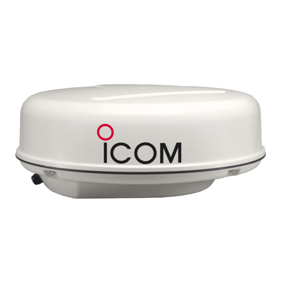
Summary of Contents for Icom MXR-5000R
- Page 1 INSTRUCTION MANUAL MARINE RADAR MXR-5000R (Radome type) MXR-5000T (Open array type) This device complies with Part 15 of the FCC Rules. Op- eration is subject to the condition that this device does not cause harmful interference.
-
Page 2: Foreword
Icom, Icom Inc. and the Icom logo are registered trademarks of Icom Incorporated (Japan) in Japan, the United States, the United Kingdom, Germany, France, Spain, Russia and/or other countries. -
Page 3: Precautions
However, if it is dropped, splash resistance cannot be For U.S.A. only guaranteed because of possible damage to the case CAUTION: Changes or modifications to this radar, or the waterproof seals. not expressly approved by Icom Inc., could void your authority to operate this device under FCC regulations. -
Page 4: Table Of Contents
RADAR OPERATOR WARNING Icom requires the radar operator to meet FAILURE TO OBSERVE THESE LIMITS MAY the FCC Requirements for Radio ALLOW THOSE WITHIN THE MPE RADIUS TO Frequency Exposure. A slotted wave- EXPERIENCE RF RADIATION ABSORPTION guide array antenna with gain not greater... -
Page 5: Panel Description
This terminal is not used. q DC POWER INPUT TERMINALS e MarineCommander™ CONNECTOR Connect the 12 V/24 V DC power supply through Connect this connector to the Icom MarineCom- the supplied DC power cable. mander™. w GROUND TERMINALS r SCANNER UNIT CONNECTOR... -
Page 6: Installation And Connections
INSTALLATION AND CONNECTIONS ■ Connection CAUTION: Before connecting, make sure discon- necting the radar unit’s DC power cable from the battery. Ground Radar unit Supplied scanner unit Terminal guard NEVER connect anything other Detach the terminal guard first. than the supplied scanner unit. MarineCommander™... -
Page 7: Mounting The Ex-2714 Scanner Unit
INSTALLATION AND CONNECTIONS ■ Mounting the EX-2714 scanner unit D Location D Mounting q Drill four holes of 12 mm (0.47 in) in diameter using R WARNING! BE SURE the radar’s power is OFF* the supplied template. whenever you are working with the scanner unit. w If the mounting surface or platform is metal, apply * The radar’s power automatically turns OFF approx. -
Page 8: Wiring The Ex-2714 System Cable
INSTALLATION AND CONNECTIONS ■ Wiring the EX-2714 system cable CAUTION: NEVER cut the supplied system cable. y Connect the power cable (black and red) to the q Using a hex head wrench*, loosen the four bolts on power connector. (t) the bottom of the scanner unit, and open the unit. -
Page 9: Mounting The Ex-2780 Scanner Unit
INSTALLATION AND CONNECTIONS ■ Mounting the EX-2780 scanner unit D Location y The mounting surface must be parallel with the R WARNING! BE SURE the radar’s power is OFF* boat’s waterline. whenever you are working with the scanner unit. u If the height is insufficient to install the scanner unit, * The radar’s power automatically turns OFF approx. -
Page 10: Wiring The Ex-2780 System Cable
INSTALLATION AND CONNECTIONS ■ Wiring the EX-2780 system cable CAUTION: NEVER cut the supplied system cable. q Loosen the four bolts on the bottom of the scan- ner body using the supplied allen wrench (q), and open the top cover (w). w Loosen the nut on the scanner unit and pass the system cable through the nut and sealing tube. -
Page 11: Attaching The Ex-2780 Scanner Unit
INSTALLATION AND CONNECTIONS ■ Attaching the EX-2780 scanner unit NOTE: When using the optional system cable. q Put the scanner unit on the stay, then attach the an- Peel the outer sheath of the system cable when tenna rotor with the supplied bolts (M8×18 mm ) , flat using the optional system cable OPC-1078. -
Page 12: Maintenance And Options
Allows you to install the radar unit and scanner unit an Icom transceiver in the event the Icom transceiver is up to 20 m (65.6 ft) apart. (For MXR-5000R only) used with equipment that is not manufactured or approved • OPC-1078 system cable by Icom. -
Page 13: Specifications
• DC input voltage : 10.8 V to 31.2 V DC • Power consumption : Less than 5.0 A at 12.0 V (MXR-5000R) Less than 5.5 A at 12.0 V (MXR-5000T) • Usable temperature range : –20°C to +60°C; –4˚F to 140˚F •... - Page 14 MEMO...
- Page 15 MEMO...
- Page 16 A-6752H-1EX-w Printed in Japan 1-1-32 Kamiminami, Hirano-ku, Osaka 547-0003, Japan © 2009–2011 Icom Inc.


Need help?
Do you have a question about the MXR-5000R and is the answer not in the manual?
Questions and answers