Icom MR-1000RII Instruction Manual
Radome type, open array type; 4 kw, 6 kw
Hide thumbs
Also See for MR-1000RII:
- Instruction manual (47 pages) ,
- Instruction manual (47 pages) ,
- Specifications (2 pages)

Subscribe to Our Youtube Channel
Related Manuals for Icom MR-1000RII


Summary of Contents for Icom MR-1000RII
- Page 1 INSTRUCTION MANUAL MARINE RADAR MR-1000R™ (Radome type) MR-1000T™ (Open array type; 4 kW) MR-1000T (Open array type; 6 kW)
-
Page 2: System Components
SYSTEM COMPONENTS MODEL NAME CRT DISPLAY SCANNER UNIT MR-1000RII SX-2713 (10-inch CRT) EX-2714 (Radome type) MR-1000TII EX-2780 (Open array type; 4 kW) SX-2779 (10-inch CRT) MR-1000TIII EX-2780 (Open array type; 6 kW) SUPPLIED ACCESSORIES • EX-2714 (Radome type unit) • SX-2713/SX-2779 (10-inch CRT display unit) Qty. -
Page 3: Important
The MR-1000RII/TII/TIII are supplemental aids to navigation and are not intended to be a substitute for accurate and current nautical charts. FOREWORD BE CAREFUL! Thank you for purchasing Icom’s MR-1000RII/TII/TIII SART signals may not be detected and may marine radar not be displayed on the screen depending The radar is designed especially for fishing boats. -
Page 4: Precautions
PRECAUTIONS For Display unit: For Scanner unit: WARNING! NEVER R DANGER: HIGH VOLTAGE! NEVER let metal, wire or other open objects touch any internal part of the display unit. This the scanner unit. The scanner unit contains high volt- may result in an electric shock. age that could be fatal. -
Page 5: Table Of Contents
TABLE OF CONTENTS SYSTEM COMPONENTS ......... i ■ Multiple echoes ..........21 SUPPLIED ACCESSORIES ........i ■ Minimum range ..........21 FOREWORD ............ii ■ Blind and Shadow sectors ......22 IMPORTANT ............. ii ■ Target resolution ..........22 EXPLICIT DEFINITIONS .......... ii 8 INSTALLATION AND CONNECTIONS .. -
Page 6: Panel Description
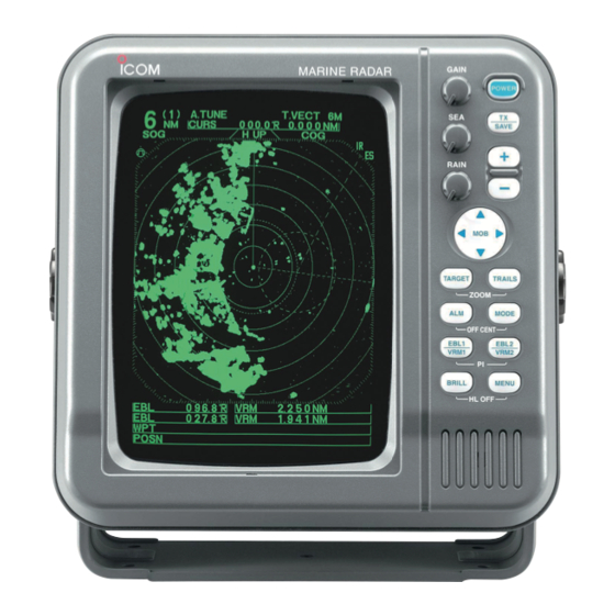
PANEL DESCRIPTION ■ Front panel GAIN POWER MARINE RADAR GAIN SAVE POWER SAVE RAIN RAIN TARGET TRAILS ZOOM MODE OFF CENT EBL1 EBL2 VRM1 VRM2 BRILL MENU TARGET TRAILS HL OFF ZOOM MODE OFF CENT EBL1 EBL2 VRM1 VRM2 BRILL MENU HL OFF Control panel (English) - Page 7 PANEL DESCRIPTION o EBL2 (VRM2) SWITCH [EBL2 (VRM2)]/ !6 MAN OVERBOARD [MOB]/[ ] (pp. 14, 15) Push to mark the man overboard point on the Push to display the electronic bearing line 2 (EBL2) screen. When a crew member falls overboard, hold and the variable range marker 2 (VRM2), and acti- down [MOB]/[ ] for 1 second to display the MOB...
-
Page 8: Screen
PANEL DESCRIPTION ■ Screen (0.25) MTUNE TVECT TRAILS 0 05 0174˚R 0649NM NM CURS H UP HDG2530˚T STW157 KT COMPASS ZOOM EBL1 1076˚ VRM1 0422NM 0 01 0 00 EBL2 0219˚ VRM2 0242NM 0 01 2834˚ 0632NM CURS 34˚ 39720N 135˚... - Page 9 PANEL DESCRIPTION #5 COMPASS INDICATOR (pp. 23, 38) $4 IR INDICATOR (p. 10) • GYRO : NMEA (gyro) is connected. Eliminates or reduces interference caused by other • COMPASS : NMEA (compass), N+1 or AUX data is radar operating nearby. connected.
-
Page 10: Menu
MENU ■ VIDEO ■ FUNCTION VIDEO MENU FUNCTIONMENU AUTO TUNE MANUAL RING MID. WIDE D.RANGE NAR. SHIP CURS POSN DISP DIST UNIT STRETCH TRUE PULSE EBL/PI TRUE ˚ PT/SB ZONE ALARM TRAIL TIME BEEP D TUNE D RING • AUTO : Automatic tuning. -
Page 11: Ata (Automatic Tracking Aid)
MENU ■ ATA (Automatic Tracking Aid) ■ INT. SETTING INT. SETTING A T A MENU AUTO MAG VAR MANUAL A T A ˚ No.DISP BRG INPUT NMEA VECT TRUE SPD INPUT OWN VECT TX INH START ˚ ALARM TX INH ANGLE ˚... -
Page 12: Basic Operation
BASIC OPERATION ■ Checking the installation D Checklist Before turning ON the power, be sure all the connec- tions are complete. The checklist at right may be help- q The four bolts securing the scanner unit must be ful for necessary confirmation. firmly tightened. -
Page 13: Basic Operation
BASIC OPERATION ■ Basic operation q Turn ON the power. GAIN w Push [TX]/[ ] after the countdown disap- POWER pears from the screen. • See “Turning power ON/OFF” on page at left. SAVE e Push [+]/[ ] or [–]/[ ] one or more times to select the display range. -
Page 14: Rain Function
BASIC OPERATION The following are typical basic operation examples, which may hinder radar reception (sea clutter, precipitation interference and echoes from other radar). ■ RAIN function This function eliminates echoes from rain, snow, fog etc. • Rotate the control fully counterclockwise to deactivate the control function. -
Page 15: Ir Function
BASIC OPERATION ■ IR function Radar interference may appear when another ship’s radar is operating on the same frequency band in close proximity. The IR function can eliminate this type of interference. (p. 5) q Push [MENU]/[ ] to call up VIDEO menu. w Hold down [q] until the “IR”... -
Page 16: Trails Function
BASIC OPERATION ■ TRAILS function • Setting the trail interval time The trails function memorizes echoes continuously or q Push [MENU]/[ ] to call up the VIDEO menu. at constant intervals. This is useful for watching other ships’ tracks, approximately relative speed, etc. •... -
Page 17: Ship Speed Indication
BASIC OPERATION ■ Ship speed indication ■ Long pulse function When the ship speed data in NMEA 0183 format is ap- To magnify the blips for easier viewing of small tar- plied, the radar can display the ship speed. Knots (KT) gets, the long pulse and echo stretch (p. -
Page 18: Distance And Direction Measurements
DISTANCE AND DIRECTION MEASUREMENTS ■ Distance measurement Two measurement procedures can be used with this TYPE DESCRIPTION radar. Use them separately or jointly is possible. Displays fixed rings. RING The distance unit, nautical miles (NM) or kilometers Suitable for rough estimations from your own ship to any target. -
Page 19: Bearing And Distance Measurement
DISTANCE AND DIRECTION MEASUREMENTS ■ Bearing and Distance measurement This radar has two Electronic Bearing Lines (EBL) to indicate the target direction from your ship or a target. D Using the EBL and VRM q Push [p] [q] [t] [u] to move the cursor onto the TVECT 3240R NM CURS... -
Page 20: Advanced Measurements
DISTANCE AND DIRECTION MEASUREMENTS ■ Advanced measurements Using both Electronic Bearing Lines (EBL) and both Variable Range Markers (VRM), the following ad- vanced measurements can be made: D Measuring the distance and direction between two targets q Push [p] [q] [t] [u] to move the cursor onto the MTUNE TVECT NM CURS\... -
Page 21: Alarm Function
ALARM FUNCTION The unit has an alarm function to protect your ship from collisions. If other ships, islands or other obstructions. come into the pre-programmed alarm zone, the function alerts you with an alarm. You can set the desired range and bearing for an alarm zone. -
Page 22: Ata (Automatic Tracking Aid)
ATA (Automatic Tracking Aid) ■ ATA (Automatic Tracking Aid) By automatically tracking the target chosen by the cursor key, the closest point of approach (CPA) and the time to closest point of approach (TCPA) limit of your ship and a target are calculated. ATA is the function to tell about to alarm sound, when both CPA and TCPA becomes below a setting value (the ap- proach watch area). -
Page 23: Ata Operation
ATA (Automatic Tracking Aid) ■ ATA operation Select the target on the display which you want to track. q Push [p] [q] [t] [u] to move the “+” cursor onto the DIST desired target. TCPA w Hold down [TARGET]/[ ] for 1 second to select the target for tracking. -
Page 24: Plots
ATA (Automatic Tracking Aid) ■ Plots Plot displays the target’s past positions of targets every 1 minute as 3 dots. q Target goes straight. w Target turns right. e Target reduces speed (dots are closer together behind the target). r Target increases speed (dots are father apart be- hind the target). -
Page 25: Basic Radar Theory
BASIC RADAR THEORY Radar uses a form of electromagnetic radiation which, like light, can be reflected. Because of this property, some objects may cause false echoes on the screen where in fact no targets actually exist. These echoes may appear if a large vessel, bridge, or other metal object is in proximity. Operators should be famil- iar with the effect of this phenomena. -
Page 26: Multiple Echoes
BASIC RADAR THEORY ■ Multiple echoes Multiple echoes will appear beyond the target’s true Multiple echoes may appear when a short-range and echo point on the same bearing of a large target. They strong echo is received from a ship, bridge, or break- can be reduced with proper adjustment of the [SEA]/ water. -
Page 27: Blind And Shadow Sectors
BASIC RADAR THEORY ■ Blind and Shadow sectors When tall and massive targets such as a large island Blind or Shadow sectors may exist because of obstruc- are located at close range also shadowed without pro- tions such as masts, derricks or other metal objects. ducing any echoes. -
Page 28: Installation And Connections
INSTALLATION AND CONNECTIONS ■ Connecting the units Power supply Display unit 10.2 to 42 V DC Red: Black: _ Supplied scanner unit NEVER connect anything other than the supplied Ground scanner unit. NMEA2: NMEA1: NMEA 0183 data input Bearing data input Speed sensor input NMEA1 connection (Rear panel view) NMEA2 connection (Rear panel view) -
Page 29: Installing The Display Unit
INSTALLATION AND CONNECTIONS ■ Installing the display unit D Mounting D Location The mounting bracket supplied with the display unit al- Select a place for installation which meets the follow- lows “dashboard” or “overhead” mounting. ing important conditions: q Hold the mounting bracket up to the selected lo- ➥... -
Page 30: Mounting The Ex-2714 Scanner Unit
INSTALLATION AND CONNECTIONS ■ Mounting the EX-2714 scanner unit D Location D Mounting The scanner unit is designed for high-pressure water WARNING! BE SURE [POWER]/[ jet resistance (except for the cable connectors). Select is OFF whenever you are working with the scanner a place for installation which meets the following im- unit. -
Page 31: Wiring The Ex-2714 System Cable
INSTALLATION AND CONNECTIONS ■ Wiring the EX-2714 system cable CAUTION: NEVER cut the supplied system cable. q Using a hex head wrench*, loosen the four bolts on y Connect the power cable (black and red) to the the bottom of the scanner unit, and open the unit. power connector. -
Page 32: Mounting The Ex-2780 Scanner Unit
INSTALLATION AND CONNECTIONS ■ Mounting the EX-2780 scanner unit D Location D Mounting The scanner unit is designed for high-pressure water WARNING! BE SURE [POWER]/[ jet resistance (except for the cable connectors). Select is OFF whenever you are working with the scanner a place for installation which meets the following im- unit. -
Page 33: Wiring The Ex-2780 System Cable
INSTALLATION AND CONNECTIONS ■ Wiring the EX-2780 system cable CAUTION: NEVER cut the supplied system cable. q Loosen the four bolts on the bottom of the scanner unit body using the supplied allen wrench (q), and open the top cover. (w) w Loosen the sealing nut on the scanner unit and pass the system cable through the sealing nut and seal- ing tube. -
Page 34: Attaching The Ex-2780 Scanner Unit
INSTALLATION AND CONNECTIONS ■ Attaching the EX-2780 scanner unit NOTE: When using the optional system cable. q Put the scanner unit on the stay, then attach the Peel the outer sheath of the system cable when antenna rotor with the supplied bolts (M8×18 mm), using the optional system cable OPC-1078A. -
Page 35: Other Functions
OTHER FUNCTIONS D Antenna rotation speed • MR-1000RII: [CHN], [CHN-01], [EXP], [EXP-01] • MR-1000TII, MR-1000TIII The antenna rotation speed can be selected between 48 rpm and 36 rpm. (Default: 48 rpm) Hold down [–]/[ ] for 1 second to select 36 rpm, hold down [+]/[ ] for 1 second to select 48 rpm. -
Page 36: Service Man Menu
SERVICE MAN MENU ■ Service man menu SERVICE MAN ENGLISH TIMING ADJ. OUTPUT VOLTAGE 3 0 . 0 CAUTION: The SERVICE MAN MENU is available HDG ADJ. ˚ 3 4 0 for service purposes only. DO NOT change any SPD ADJ. 2 4 0 0 0 MONITOR 0 . -
Page 37: Timing Adjustment
SERVICE MAN MENU ■ TIMING adjustment e Push [TX (SAVE)]/[ ] to display the target The system cable length affects the sweep timing. on the screen. When the cable length adjustment is not correct, a r Push [MENU]/[ ], [q] and [u] one or more times straight target is shown as a curved echo. -
Page 38: Spd Adjustment
SERVICE MAN MENU ■ SPD adjustment q Push [MENU]/[ ], [q] and [u] one or more times to display the “SERVICE MAN” menu. w Hold down [q] until the “SPD ADJ.” section be- comes highlighted. e Push [t] [u] to enter the pulse rate of the speed sensor unit (pulse numbers per one nautical mile). -
Page 39: Error Message
ERROR MESSAGE ■ Error message list Message Condition BRG INPUT FAIL* • The Azimuth signal is interrupted. An alarm sounds within 5 seconds and the display reverts to H UP mode in approximately 1 minute. TRIG SIGNAL FAIL* • If the TRIGGER signal is interrupted for more than 15 seconds, an alarm sounds. -
Page 40: Maintenance
MAINTENANCE Continued, reliable operation of the radar depends on how you care for it. The simple maintenance tips that follow can help you save time and money, and avoid premature equipment failure. ■ Periodic maintenance q Keep the equipment as clean as possible. WARNING: BE SURE [POWER]/[... -
Page 41: Specifications
: 25 m; 82 ft (when measurement range is ⁄ • Maximum range : 36 NM (MR-1000RII; when measurement range is 36 NM) 48 NM (MR-1000TII; when measurement range is 48 NM) 72 NM (MR-1000TIII; when measurement range is 72 NM) •... -
Page 42: Scanner Unit
SPECIFICATIONS D Scanner unit ◆ EX-2714 (Radome) • Type : 2 feet Slotted Waveguide Array, enclosed in a radome. • Rotation speed (typical) : 24 rpm, 36 rpm, 48 rpm* *only [CHN], [CHN-01], [EXP], [EXP-01] • Beam width (typical) : Horizontal beam 4˚... -
Page 43: External Data List
EXTERNAL DATA LIST The following external bearing, speed, position and waypoint data is (are) required , when you use the radar functions. EXTERNAL DATA INPUT NMEA1* NMEA2* “HDT”, “HDM” “RMC”, “GGA”, “GLL”, “VTG”, “WPL”, “BWC”, LOG, “GNS” N+1, AUX FUNCTION DISPLAY BEARING SPEED... - Page 45 100 mm (3 ⁄ 60 mm (2 ⁄ 30 mm (1 ⁄...
- Page 47 • EX-2714 Radome template 45.5 mm (1 ⁄ 150.5 mm (5 ⁄ Radius is 6 mm ⁄ 90.5 mm (3 ⁄ Ship’s bow direction 90.5 mm (3 ⁄...
- Page 49 • EX-2780 Open array type Radius is 6 mm ⁄ in). template 190 mm (7 ⁄ 131 mm (5 ⁄ Ship’s bow direction 131 mm (5 ⁄...
- Page 52 A-6317H-1EX-t Printed in Japan 1-1-32 Kamiminami, Hirano-ku, Osaka 547-0003, Japan © 2003–2012 Icom Inc. Printed on recycled paper with soy ink.
Need help?
Do you have a question about the MR-1000RII and is the answer not in the manual?
Questions and answers