Icom MR-1000RII Instruction Manual
Icom mr1000rii radio-marine: instruction manual
Hide thumbs
Also See for MR-1000RII:
- Instruction manual (47 pages) ,
- Instruction manual (52 pages) ,
- Specifications (2 pages)
Table of Contents
Advertisement
Quick Links
Download this manual
See also:
Instruction Manual
Advertisement
Table of Contents

Related Manuals for Icom MR-1000RII


Summary of Contents for Icom MR-1000RII
- Page 1 INSTRUCTION MANUAL MARINE RADAR MR-1000R™ (Radome type) MR-1000T™ (Open array type)
-
Page 2: System Components
!1 Grounding terminal (R5.5-10) ... 1 !2 Ferrite bead ... 1 Icom, Icom Inc. and the logo are registered trademarks of Icom Incorporated (Japan) in the United states, the United Kingdom, Germany, France, Spain, Russia and/or other countries. CRT DISPLAY... -
Page 3: Foreword
The radar is designed especially for fishing boats. It has powerful transmission power, 10 inch CRT display and many other advanced features. If you have any questions regarding the operation of the radar, contact your nearest authorized Icom Inc. dealer. IMPORTANT READ ALL INSTRUCTIONS pletely before attempting to operate the marine radar. -
Page 4: Table Of Contents
TABLE OF CONTENTS SYSTEM COMPONENTS... i SUPPLIED ACCESSORIES... i FOREWORD ... ii IMPORTANT ... ii EXPLICIT DEFINITIONS ... ii PRECAUTION ... ii TABLE OF CONTENTS ... iii 1 CAUTION ... 1 DANGER! HIGH VOLTAGE ... 1 RADIATION HAZARD ... 1 2 PANEL DESCRIPTION ... -
Page 5: Caution
The MR-1000RII/TII are supplemental aids to navigation and are not intended to be a substi- tute for accurate and current nautical charts. DANGER! HIGH VOLTAGE • NEVER OPEN THE UNIT This product contains high voltage that could be FATAL. This product has no user-service- able parts inside. -
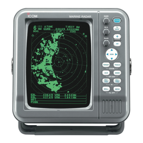
Page 6: Panel Description
PANEL DESCRIPTION I Front panel MARINE RADAR q POWER SWITCH [POWER]/[ Turns power ON and OFF. • The standby screen appears for 90 sec. while warming up the magnetron. • The initial screen appears with a beep after the power has been turned ON. - Page 7 o EBL2 (VRM2) SWITCH [EBL2 (VRM2)] ] (pgs. 15–16) Push to display the electronic bearing line 2 (EBL2) and the variable range marker 2 (VRM2), and acti- vate the [ for the electronic bearing line selec- tor and [ range marker selector. •...
-
Page 8: I Screen
PANEL DESCRIPTION I Screen @1 TUNING LEVEL INDICATOR (p. 9) Shows the receiver tuning level. @2 TUNING MODE INDICATOR (p. 9) “M.TUNE” appears when the manual tuning func- tion is in use. @3 FIXED RING RANGE READOUT (p. 14) Shows the interval range of the fixed ring. •... - Page 9 #5 COMPASS INDICATOR (pgs. 24, 39) • GYRO : NMEA (gyro) is connected. • COMPASS : NMEA (compass), N+1 or AUX data is connected. #6 EBL1/ 2 READOUTS (pgs. 15–16) Shows the bearing of the displayed Electronic Bear- ing Lines (EBL1 and EBL2) when the EBL is in use. •...
-
Page 10: Menu
MENU I VIDEO VIDEO MENU TUNE AUTO D.RANGE NAR. STRETCH PULSE TRAIL TIME D TUNE • AUTO : Automatic tuning. • “A.TUNE” appears for approx. 2 sec. instead of the screen display, when first transmitting after turning the power ON. The unit also re- tunes in some cases. -
Page 11: I Ata (Automatic Tracking Aid)
I ATA (Automatic Tracking Aid) A T A MENU A T A No.DISP TRUE VECT OWN VECT ALARM CPA LIMIT 1.0NM TCPA LIMIT 1 MIN D ATA • OFF : Turn the ATA function OFF. • ON : Turn the ATA function ON. D No.DISP •... -
Page 12: Basic Operation
BASIC OPERATION I Checking the installation Before turning the power ON, be sure all the connec- tions are complete. The checklist at right may be help- ful for necessary confirmation. CAUTION: Connect the scanner unit before turning the power ON. Otherwise the magnetron inside the scanner unit might be damaged. -
Page 13: I Basic Operation
I Basic operation GAIN POWER SAVE RAIN TARGET TRAILS ZOOM MODE OFF CENT EBL1 EBL2 VRM1 VRM2 BRILL MENU HL OFF CAUTION: When setting the [SEA]/[ a fully clockwise position, close targets are blanked. D Heading marker The heading marker is a line that shows your ship’s bow direction. -
Page 14: I Rain Function
BASIC OPERATION The following are typical basic operation examples, which may hinder radar reception (sea clutter, precipitation in- terference and echoes from other radar). I RAIN function Small echos I SEA function Echos from sea waves I OFF CENTER function Normal screen This function eliminates reflection echoes from rain, snow, fog etc. -
Page 15: I Ir Function
I IR function With IR function ON Radar interference I STRETCH function Normal screen With STRETCH ON I ZOOM function Normal screen With ZOOM function ON BASIC OPERATION Radar interference may appear when another ship’s radar is operating on the same frequency band in close proximity. -
Page 16: I Trails Function
BASIC OPERATION I TRAILS function The trails function memorizes echoes continuously or at constant intervals. This is useful for watching other ships’ tracks, approx. relative speed, etc. (0.25) T.V E C T M.T U N E C U R S 011.4˚... -
Page 17: I Ship Speed Indication
I Ship speed indication When the ship speed data with NMEA 0183 format is applied, the radar can display the ship speed. Knots (KT) or kilometers/hour (KM/h) are automatically se- lected in the normal screen (p. 4) by selecting nautical miles (NM) or kilometers (KM) respectively. -
Page 18: Distance And Direction Measurements
DISTANCE AND DIRECTION MEASUREMENTS I Distance measurement TYPE Displays fixed rings. RING Suitable for rough estimations from your own ship to any target. Displays a variable range marker and ac- tivated by the [ VRM1 selector. Suitable for accurate measurements from your own ship to a target. -
Page 19: I Bearing And Distance Measurement
I Bearing and Distance measurement D Using the EBL and VRM TVECT 3M 3240R NM CURS 1141NM SOG 00km/h H UP EBL1 VRM1 EBL2 VRM2 EBL1 readout EBL1 3151˚T VRM1 0503NM EBL2 EBL2 2471˚T VRM2 0359NM readout POSN DISTANCE AND DIRECTION MEASUREMENTS This radar has 2 Electronic Bearing Lines (EBL) to in- dicate the target direction from your ship or a target. -
Page 20: I Advanced Measurements
DISTANCE AND DIRECTION MEASUREMENTS I Advanced measurements D Measuring the distance and direction between 2 targets MTUNE NM CURS\ 3171˚M km/h H UP EBL1 VRM1 GYRO EBL1 3211˚M VRM1 0852NM EBL2 0890˚T VRM20814NM POSN D Measuring the relative speed and course of a target 3171˚M NM CURS\ H UP... -
Page 21: Alarm Function
The unit has an alarm function to protect your ship from collisions. If other ships or islands, etc. come into the pre- programmed alarm zone, the function alerts you with an alarm. You can set the desired range and bearing for an alarm zone. -
Page 22: Ata (Automatic Tracking Aid)
ATA (Automatic Tracking Aid) I ATA (Automatic Tracking Aid) By tracking automatically the target chosen by the cursor key, the closest point of approach (CPA) and the time to closest point of approach (TCPA) limit of a own ship and a target are calculated. ATA is the function to tell about to alarm sound, when both CPA and TCPA becomes below a setting value (the ap- proach watch area). -
Page 23: I Ata Operation
I ATA operation DIST TCPA Identification No. Bearing Course Distance Speed No.10 305.7T DIST 081.3T 0:20 5.9NM TCPA Closest Point of Time to Closest Point of Approach Approach Passage of time I Plotting marks I Course and speed vector Target’s predicted positon Vector Vector time... -
Page 24: I Plots
I Plots Plot displays past position of targets every 1 min. as 3 dots. q Target goes straight. w Target turns right. e Target reduces speed r Target increases speed. -
Page 25: Basic Radar Theory
Radar uses a form of electromagnetic radiation, which like light, can be reflected. Because of this property, some objects may cause false echoes on the screen where in fact no targets actually exist. These echoes may appear if a large vessel, bridge, or tank is in proximity. Operators should be familiar with the ef- fects of these phenomena. -
Page 26: I Multiple Echoes
BASIC RADAR THEORY I Multiple echoes Multiple echoes may appear when a short-range and strong echo is received from a ship, bridge, or break- water. Own ship I Minimum range Detection at short range is very important. Minimum range is determined primarily by transmitter pulse length, vertical beam width and height of the scanner unit. -
Page 27: I Blind And Shadow Sectors
I Blind and Shadow sectors Blind or Shadow sectors may exist because of ob- structions such as masts, derricks or stacks. An ob- struction may throw either a complete or partial shadow as shown in the diagram below. If a target is in a shadow sector, target echoes may not appear on the screen. -
Page 28: Installation And Connections
INSTALLATION AND CONNECTIONS I Connecting the units Supplied scanner unit NEVER connect any- thing other than the sup- plied scanner unit. NMEA1 connection q N TXT i GND (NMEA 2 output) w RXD e NMEA 1 input (+) or AUX input(+); DATA r NMEA 1 input (–) or AUX input (–);... -
Page 29: I Installing The Display Unit
I Installing the display unit D Location Select a place for installation which meets the following important conditions: q The display unit should be placed near the wheel in the cabin so that an operator may easily view the radar screen while facing the bow. w To minimize interference, KEEP the unit AT LEAST THE COMPASS SAFE DISTANCE stated in the se- rial No. -
Page 30: I Mounting The Ex-2714 Scanner Unit
INSTALLATION AND CONNECTIONS I Mounting the EX-2714 scanner unit D Location WARNING: BE SURE [POWER] is OFF when- ever you are working with the scanner unit. The scanner unit is designed to be weatherproof and completely watertight. Select a place for installation which meets the following important conditions. -
Page 31: I Wiring The Ex-2714 System Cable
I Wiring the EX-2714 system cable CAUTION: NEVER cut the supplied system cable. q Loosen the four bolts using a hex head wrench on the bottom of the scanner unit, and open the unit. w Loosen the nut on the scanner unit and pass the system cable through the nut and sealing tube. -
Page 32: I Mounting The Ex-2780 Scanner Unit
INSTALLATION AND CONNECTIONS I Mounting the EX-2780 scanner unit • Location WARNING: BE SURE [POWER]/[ OFF whenever you are working with the scanner unit. The scanner unit is designed to be weatherproof and completely watertight. Select a place for installation which meets the following important conditions. -
Page 33: I Wiring The Ex-2780 System Cable
I Wiring the EX-2780 system cable Fig. 1 Shielding wire System cable Sealing bush *Cable clamp *Ferrite bead Fig. 3 INSTALLATION AND CONNECTIONS CAUTION: NEVER cut the supplied system cable. q Loosen the four bolts using the supplied hex head wrench on the bottom of the scanner unit, and open the unit. -
Page 34: I Fixing The Ex-2780 Scanner Unit
INSTALLATION AND CONNECTIONS I Fixing the EX-2780 scanner unit q Put the scanner unit* on the stay, then fix the an- tenna rotor with installation bolts of 8 mm (5/16 in) in diameter, with flat and dish washers and a seal- ing washer. -
Page 35: Other Functions
D Antenna rotation speed The antenna rotation speed can be selected from 48 rpm and 36 rpm. (Default: 48 rpm) Pushing and holding [–]/[ ] for 1 sec. to select 36 rpm rotation speed, pushing and holding [+]/[ for 1 sec. to select 48 rpm rotation speed. D Test pattern indication To check the CRT indication distortion, a test pattern can bee displayed. -
Page 36: Service Man Menu
SERVICE MAN MENU I Service man menu CAUTION: The SERVICE MAN MENU is available for service purposes only. DO NOT change any set- ting on the menu, otherwise the equipment may not operate at it’s original performance. To open the “SERVICE MAN” menu. Push [MENU]/[ ] several times to show the “SERVICE MAN”... -
Page 37: I Timing Adjustment
I TIMING adjustment The system cable length affects the sweep timing. When the cable length adjustment is not correct, a straight target is shown as a curved echo. Thus, cable length adjustment is necessary. q Position your boat near a straight target such as breakwater, wharf, etc. -
Page 38: I Spd Adjustment
SERVICE MAN MENU I SPD adjustment I RANGE selection SERVICE MAN ENGLISH TIMING ADJ. HDG ADJ. ˚ SPD ADJ. 2 4 0 0 0 SETUP MEMORY RANGE ⁄ NM range will be skipped. q Push [MENU]/[ w Push [ ] until the “SPD ADJ.” section becomes highlighted. -
Page 39: Error Message
I Error message list Message BRG INPUT FAIL* TRIG SIGNAL FAIL* SHM SIGNAL FAIL* POSN INPUT FAIL* CHECK SCANNER CONNECTION* Push any key to cancel the error message and beep tone. Turn the power OFF, then check the external data cable connection. -
Page 40: Maintenance
MAINTENANCE Continued, reliable operation of the radar depends on how you care for your equipment. The simple maintenance tips that follow can help you save time and money, and avoid premature equipment failures. I Periodic maintenance WARNING: BE SURE the power is OFF before performing any maintenance. -
Page 41: Specifications
D D General • Minimum range • Maximum range • Measurement range • Preheat time • Connection length between display and scanner unit : 15 m; 49 D D Scanner unit N EX-2714 (Radome) • Type • Rotation speed (typical) •... - Page 42 SPECIFICATIONS D D Display unit • CRT display • Pixels • CRT mounting • Input • Power supply requirement • Power consumption (at wind velocity zero) • Usable temperature range • Relative humidity • Dimensions • Weight All stated specifications are subject to change without notice or obligation. : 10-inch green display : 640×480 dot : Vertical...
-
Page 43: External Data List
The following external bearing, speed, position and way point data is (are) required , when you use the radar func- tions. FUNCTION DISPLAY HEAD UP COURSE UP NORTH UP TRUE MOTION SPEED DISPLAY HEADING BEARING WAY POINT OWN VECTOR VRM/PI/WPT/MOB estimated time of arrival MAGNETIC VARIATION (AUTO) OG;... - Page 44 100 mm (3 ⁄ 60 mm (2 ⁄ 30 mm (1 ⁄...
- Page 45 • EX-2714 Radome template Ship’s bow direction 45.5 mm (1 ⁄ 150.5 mm (5 Radius is 6 mm ⁄ ⁄ 90.5 mm (3 ⁄ 90.5 mm (3 ⁄...
- Page 46 •EX-2780 Open array type template Ship’s bow direction Radius is 6 mm ⁄ in). 190 mm (7 ⁄ 131 mm (5 ⁄ 131 mm (5 ⁄...
- Page 47 A-6317H-1EX-q Printed in Japan 1-1-32 Kamiminami, Hirano-ku, Osaka 547-0003, Japan © 2003–2004 Icom Inc.
Need help?
Do you have a question about the MR-1000RII and is the answer not in the manual?
Questions and answers