Table of Contents
Advertisement
Advertisement
Table of Contents

Related Manuals for Icom MR-1010RII


Summary of Contents for Icom MR-1010RII
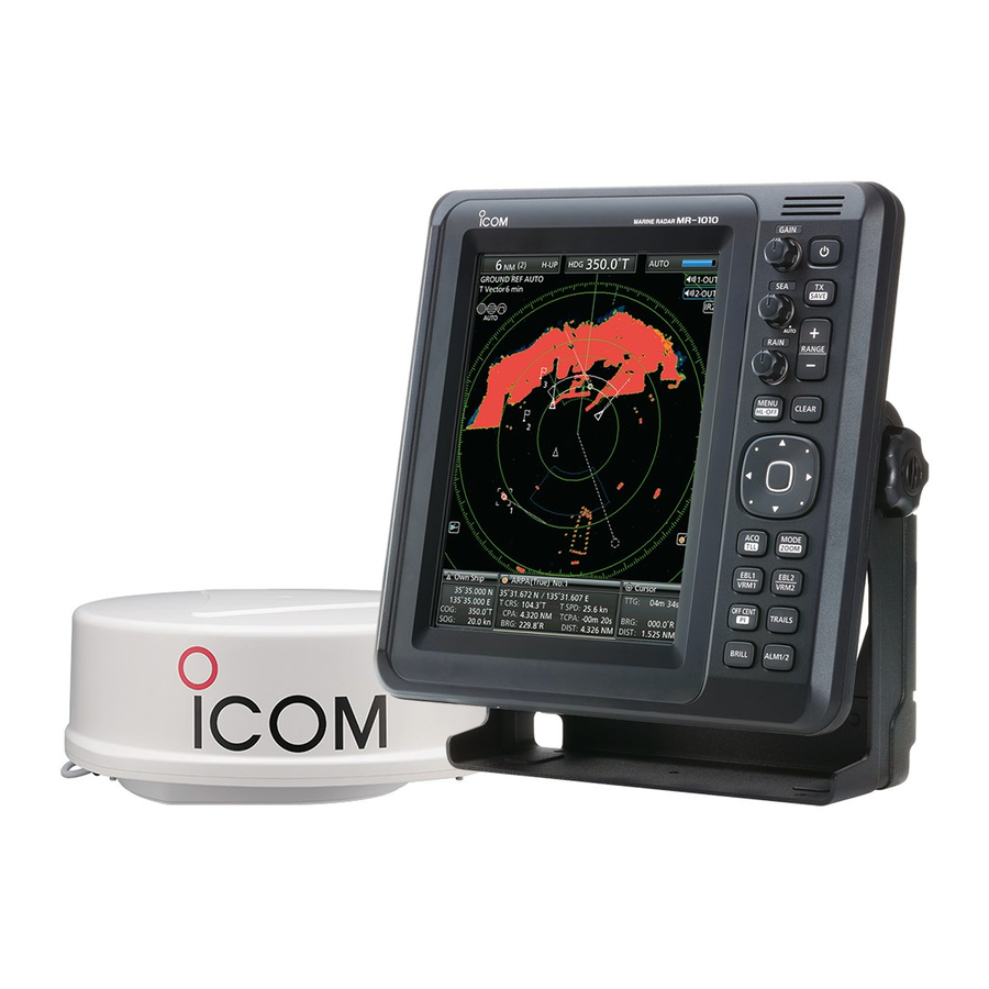
- Page 1 INSTRUCTION MANUAL MARINE RADAR MR-1010R™...
-
Page 2: Supplied Accessories
SYSTEM COMPONENTS MODEL NAME DISPLAY UNIT SCANNER UNIT MR-1010RII 10.4-inch Color LCD EX-2714 (Radome type) SUPPLIED ACCESSORIES z 10.4-inch Color LCD display unit z Scanner unit (EX-2714) Quantity Quantity 1. NMEA connector (PLT-167-P-R) ......1 1. System cable (10 m) ........... 1 2. -
Page 3: Important
The MR-1010RII is a supplemental aid to navigation and is not intended to be a substitute for accurate and current nautical charts. Thank you for choosing this Icom product. The BE CAREFUL! MR-1010RII is designed and built with marine radar Icom's state of the art technology and craftsmanship. -
Page 4: Precautions
PRECAUTIONS For Display unit: However, if it is dropped, splash resistance cannot be guaranteed because of possible damage to the case R WARNING! NEVER let metal, wire or other or the waterproof seals. objects contact the inside of the display unit, or make incorrect contact with connectors on the rear panel. -
Page 5: Table Of Contents
■ Antenna rotation speed ........35 ■ Timing adjustment ........... 35 • Display mounting bracket template ■ Heading adjustment ........36 • MR-1010RII OPERATING GUIDE ■ Range selection ..........37 ■ Save and load settings ........37 ■ Resetting ............38... -
Page 6: Panel Descriptions
PANEL DESCRIPTIONS ■ Front panel Control panel (English) Control panel (Chinese) y ENTER KEY* q POWER KEY (p. 7) z Push to turn the radar power ON or OFF. *Described as [ENTER]/[ ] in this manual. Push to select the target and display the ARPA, •... - Page 7 PANEL DESCRIPTION i EBL2 (VRM2) KEY [EBL2 (VRM2)]/ !3 EBL1 (VRM1) KEY [EBL1 (VRM1)]/ ] (pp. 17–20) ] (pp. 17–20) z Push to display the EBL2 and the VRM2. z Push to display the EBL1 and the VRM1. EBL: Electronic Bearing Line EBL: Electronic Bearing Line VRM: Variable Range Marker VRM: Variable Range Marker...
-
Page 8: Screen
PANEL DESCRIPTION ■ Screen This Display example is set to Wide in the “PPI Area” item of the Display menu. q SCREEN RANGE READOUT (p. 17) r HEADING INDICATOR (p. 15) Displays the range of the current screen. Displays the heading readout.The HDG readout indicates the bow of the ship’s heading in a Indicator Description... - Page 9 PANEL DESCRIPTION i TRAILS INDICATOR (p. 12) !8 INFORMATION BOX (pp. 14, 23, 26, 32) Displays the trail reference and the trail time. Displays a detailed information of a selected target, • The echo remains, with gradation, during the trail time such as AIS, ARPA, TLL, Waypoint, or, DSC.
- Page 10 PANEL DESCRIPTION ■ Screen (Continued) #3 8 @8 OWN SHIP VECTOR INDICATOR (p. 6) #1 WAYPOINT MARKER (p. 14) Displays the vector of your own ship. Displays a waypoint that is received from navigation equipment. @9 PARALLEL INDEX LINES (p. 17) •...
- Page 11 PANEL DESCRIPTION #8 POPUP MESSAGE (p. 32) #6 ALARM ZONE (p. 14) A message pops up when the radar received the Displays the alarm zone. data of the target, such as a DSC, or favorite AIS • Displays when the alarm function is in use. that you have selected.
-
Page 12: Basic Operation
ON the power, when “Auto” is selected in the “TUNE” item of the Video menu. NOTE: At the first turning ON the MR-1010RII or after performing Factory Reset, the Initial Setting screen is displayed. Push [p] or [q] to select a language, and push [ENTER]. -
Page 13: Adjusting Brilliance And Color
BASIC OPERATION ■ Adjusting brilliance and color D Selecting the display color D Adjusting the display brilliance The Day (white background), Night (black The brilliance of the screen can be adjusted. When background), and User settings are selectable. you require continuous operation, but not constant viewing, a lower setting can increase the life of the 1. -
Page 14: Adjusting The Screen
BASIC OPERATION ■ Adjusting the screen The followings are typical basic operation examples D RAIN function that may hinder radar reception (sea clutter, This function eliminates echoes from rain, snow, fog, precipitation interference and echoes from other and so on. radar). -
Page 15: Off Center Function
BASIC OPERATION ■ OFF CENTER function The scanning area can be shifted in direction and can be partially enlarged. This is useful when the Head-up screen is selected, and you want to enlarge the bow direction display, or the center of the screen shifts in the direction of the intersection. -
Page 16: Echo Stretch Function
BASIC OPERATION ■ Echo Stretch function (MENU w Video w Echo Stretch) The blips can be magnified electronically for easier viewing of small targets. 1. Push [MENU]/[ ] to display the Menu screen. 2. Push [t] or [u] to select the Video menu. 3. -
Page 17: Trail Function
BASIC OPERATION ■ Trail function The trail function memorizes echoes continuously or 1. Push [MENU]/[ ] to display the Menu screen. at constant intervals. This is useful for watching other 2. Push [t] or [u] to select the Trail menu. vessels’... -
Page 18: Power Save Function
BASIC OPERATION ■ Power save function The power save function conserves the vessel's battery power by pausing the transmission. The standby (pausing) times are selectable (rotation number is fixed to 10). For example, when 1 minute is selected, the scanner rotates 10 revolutions, then stops for 1 minute, and then repeats this sequence while the power save mode is activated. -
Page 19: Ship Speed Indication
BASIC OPERATION ■ Ship speed indication When the ship speed data in NMEA 0183 format is (MENU w Initial w Speed Unit) applied, the radar can display the ship speed. 1. Push [MENU]/[ 2. Push [t] or [u] to select the Initial menu. 3. -
Page 20: Bearing Settings
BASIC OPERATION ■ Bearing settings (MENU w System w Bearing Mode) The radar bearing interface accepts NMEA, N+1, AUX, or COG data format and the bearing can use a T: True north magnetic or true north type. When a true north type M: Magnetic north bearing is used, the variation from magnetic north can be adjusted on 0.1˚... - Page 21 • Until an effective variation is received, use 0° for difference between true North and magnetic North. After an effective variation is received, use the last data for the difference. The MR-1010RII memorize the data until you turn OFF the power.
-
Page 22: Distance And Direction Measurements
DISTANCE AND DIRECTION MEASUREMENTS ■ Distance measurement Various ways to measure the distance are provided with this radar. L You can select a distance unit from nautical miles (NM), or kilometers (kn) in the Initial menu (p. 45). TYPE DESCRIPTION Displays fixed rings. -
Page 23: Bearing And Distance Measurement
DISTANCE AND DIRECTION MEASUREMENTS D Using the variable range marker 1. Push [EBL1 (VRM1)]/[ ] to display 4. Push [ENTER]/[ ] to set the EBL/VRM2 the VRM1 and EBL1, then push [p] or [q] to set setting. the marker. 5. Push [EBL1 (VRM1)]/[ ] to clear the •... -
Page 24: Advanced Measurements
DISTANCE AND DIRECTION MEASUREMENTS ■ Advanced measurements Using both Electronic Bearing Lines (EBL) and both Variable Range Markers (VRM), the following advanced measurements can be made. D Measuring the distance and direction between two targets 1. Move the cursor onto the desired target. 2. - Page 25 DISTANCE AND DIRECTION MEASUREMENTS D Measuring the distance and course from a waypoint 1. Display a waypoint as described on page 14. 2. Push [EBL1 (VRM1)]/[ ] to display the EBL1 and VRM1, and then set the VRM1 and EBL1 to the waypoint. •...
-
Page 26: Alarm Function
.” D Entering the power save mode Fig. 2 The Alarm function is also available when the MR-1010RII is in the power save mode. z Hold down [TX (SAVE)]/[ ] for 1 second while the Alarm function is ON. • The power save mode is activated and the display turns OFF. -
Page 27: Setting Zone Alarm Type
ALARM FUNCTION ■ Setting Zone alarm type A zone alarm sounds when the target comes into the (MENU w System w Zone Alarm1) zone, or when the target goes out of the zone. (p. 13) (MENU w System w Zone Alarm2) 1. -
Page 28: The Simplified Arpa Operation
THE SIMPLIFIED ARPA OPERATION The simplified Automatic Radar Plotting Aids (ARPA) function is designed to help prevent a collision with other vessels or landmasses. The radar automatically acquires and plots other vessels and landmasses that are in the set watch area. It automatically calculates the closest point of approach (CPA), and the time to closest point of approach (TCPA) limit of your vessel and the targets, and sounds an alarm if there is a danger of colliding with them. -
Page 29: Descriptions Of Arpa Targets
THE SIMPLIFIED ARPA OPERATION ■ Descriptions of ARPA targets D The status icons The followings are the status icons for APRA targets. Status Description Focused target is displayed with the orange colored circle Selected target is displayed with corners of the square Selected, started to acquire automatically or manually. -
Page 30: Arpa Settings
Plotting Aid) function. • ON: Turns ON the ARPA function. Auto Acquire (Default: OFF) Sets whether the MR-1010RII automatically acquires targets or not. • OFF: Does not automatically acquire a target. • ON: Automatically acquires up to 5 targets. Track (Default: OFF) The plot displays the target’s past positions as 5 dots,... -
Page 31: Ais Receiver
AIS RECEIVER ■ About AIS The Automatic Identification System (AIS) is primarily used Other vessel for collision-risk management and navigation safety. It (Class A AIS) automatically transmits and receives vessel information, Other vessel such as the vessel name, MMSI code, vessel type, position (Class B AIS) data, speed, course, destination and more. -
Page 32: Description Of The Ais Display
AIS RECEIVER ■ Description of the AIS display D AIS target icons The AIS targets are displayed with an icon described below, depending on the type of the target. Icon Description Vessel (p. 28) The tip of the target triangle automatically points in the direction it’s heading. - Page 33 AIS RECEIVER D Status of the vessel icon D Plots (AIS) There are 5 kinds of target vessel status. The plot displays the activated target, SAR, SART, MOB, or EPIRB’s past positions as 5 dots, during Sleeping target: each specified tracking interval. The AIS signal has been updated (received), •...
-
Page 34: Ais Settings
New Target Warning (Default: OFF) Sets whether the MR-1010RII gives a warning when the Auto Activate function automatically turns the sleeping AIS target into an activated target, or not. • OFF: Does not give a warning when the Auto Activate function activates the target. - Page 35 AIS RECEIVER Erase Lost Target (Default: ON) Erases all of the Lost targets at the same time. When there are no lost targets, this setting grays out. 1. Push [ENTER]/[ 2. Push [t] to select <OK>. 3. Push [ENTER]/[ ] again to clear all of the Lost targets on the screen.
-
Page 36: Related Settings
D System menu You can display the AIS targets in the Standby mode. Set the STBY Mode setting to “AIS” in the System menu to display the AIS targets when the MR-1010RII is in the Standby mode. -
Page 37: Other Functions
• The readout pops up that includes the “Received DSC,” format of the DSC, sender's MMSI, and the nature of distress are displayed. DSC Display (Default: Symbol & Pop-up) Sets whether the MR-1010RII displays the DSC information or not. • OFF: DSC information is not displayed. • Symbol: A Symbol is displayed. -
Page 38: Tll Function
OTHER FUNCTIONS ■ TLL function The TLL (Target Latitude and Longitude) function marks the target on the display or outputs its data to an external unit. (MENU w System w TLL Mode) D TLL setting 1. Push [MENU]/[ ] to display the Menu screen. 2. -
Page 39: Select The Language
], push [ ] to turn ON the power. • After the opening screen, the standby screen is displayed. While the MR-1010RII is in the simulation mode, “Simulation Mode” is displayed in the upper of the screen. 2. Push [TX (SAVE)]/[ ] to operate in the simulation mode. -
Page 40: Antenna Rotation Speed
OTHER FUNCTIONS ■ Antenna rotation speed The antenna rotation speed can be selected between (MENU w Initial w Antenna Rotation Speed) Normal (36 rpm) and Slow (24 rpm) in the 1/2, 1/4 or 1/8 range. 1. Push [MENU]/[ ] to display the Menu screen. 2. -
Page 41: Heading Adjustment
OTHER FUNCTIONS ■ Heading adjustment If the heading marker line differs from the exact bow (MENU w Initial w Heading Adjust) direction, adjust the heading marker line manually. This may be helpful when the scanner has not been mounted correctly in the line with the bow. 1. -
Page 42: Range Selection
9. Push [MENU]/[ ] to exit the Menu screen. ■ Save and load settings The MR-1010RII can save three different settings (MENU w Initial w Save Settings1, 2, or 3) for different operators or different situations, and immediately change from one to another. -
Page 43: Resetting
OTHER FUNCTIONS ■ Resetting The MR-1010RII has two reset modes. One is "Setting Reset" and the other is "Factory Reset." "Setting Reset" resets all of the settings other than the settings in the Initial menu. "Factory Reset" resets all of the settings including the settings in the Initial menu. -
Page 44: Menu Screen
MENU SCREEN ■ Operation in the Menu screen 1. Push [MENU]/[ ] to display the Menu screen. Ring Brill* (Default: 3) • OFF: T he fixed range rings are not displayed, and the scale is displayed dark. • 1 to 3: The range rings and the scale are displayed in 1 (dark), 2 (normal) or 3 (bright). -
Page 45: Trail Menu
The true trail Sets whether after no operation is performed for 10 requires a heading signal and your own seconds, the MR-1010RII hides the outside of the vessel’s position information, therefore a scale or not. stopped target’s trail is not displayed. -
Page 46: Target Menu
CPA/TCPA Alarm (Default: ON) Sets whether the MR-1010RII sounds the CPA/TCPA alarm, or not. A CPA/TCPA alarm sounds when both the CPA and TCPA reach the limit. -
Page 47: Ais Menu
• 5 to 180°: Select the angle with your vessel. New Target Warning (Default: OFF) Sets whether the MR-1010RII gives a warning when the Auto Activate function automatically changes the sleeping AIS target to an activated target, or not. • OFF: Does not give a warning when the Auto Activate function activates the target. -
Page 48: Video Menu
MENU SCREEN ■ AIS menu (Continued) Erase Lost Target Dynamic Range (Default: Narrow) Erases all of the Lost targets at the same time. Selects the dynamic range of the Plan Position When there is no lost targets, this setting is grayed Indicator (PPI). - Page 49 (Default: Heading Line) an effective variation is received, the received data is valid until you turn OFF Selects the objects which are temporarily hidden the MR-1010RII. while [HL-OFF] is hold down. • Manual: Manually revises magnetic variation. • Heading Line: Hides the Heading line.
-
Page 50: Initial Menu
Selects the unit of distance from NM (Nautical miles) +180°. (p. 36) or km (Kilometers). Antenna Rotation Speed (Default: Normal) L You can change this setting only while the MR-1010RII is in the Standby mode. Selects the antenna rotation speed from Normal or Slow. (p. 35) Speed Unit... -
Page 51: Ais Own Menu
Setting Reset Resets the settings in the Menu screen other than the settings in the Initial menu. You can reset only while the MR-1010RII is in the Standby mode. (p. 38) 1. Push [ENTER]/[ 2. Push [t] to select <OK>. -
Page 52: Basic Radar Theory
BASIC RADAR THEORY Radar uses a form of electromagnetic radiation that can be reflected off a large vessel, bridge, or other metal objects that are in proximity. Because of this property, unwanted reflections off some objects may cause false echoes to appear on the screen where in fact no actual targets exist. Operators should be familiar with the effect of this phenomena. -
Page 53: Multiple Echoes
BASIC RADAR THEORY ■ Multiple echoes Multiple echoes may appear when a short-range Multiple echoes will appear beyond the target’s true and strong echo is received from a vessel, bridge, or echo point on the same bearing of a large target. breakwater. -
Page 54: Target Resolution
BASIC RADAR THEORY ■ Target resolution Target resolution is determined by the horizontal beam width and transmit pulse width. Sometimes it is difficult to detect two targets that are separated by short distances or are in the same direction. D Distance resolution D Direction resolution When two targets are separated by more than the When two targets are separated by more than the... -
Page 55: Maintenance
MAINTENANCE Continued, reliable operation of the radar depends on how you care for it. The simple maintenance tips that follow can help you save time and money, and avoid premature equipment failure. ■ Periodic maintenance 1. Keep the equipment as clean as possible. WARNING! BE SURE to turn OFF the radar L Use a soft cloth to remove dirt, dust and water. -
Page 56: Error Messages
ERROR MESSAGES ■ Error message list Message Condition Check Scanner Connection* The system cable may not be properly connected. The data from the Scanner unit can be received, but it is incorrect data. Communication error (Scanner) This is possibly a bad cable or bad connection, or a malfunction from other equipment noise. -
Page 57: Specifications
SPECIFICATIONS ■ General • Minimum range: 25 m, 82 ft (when measurement range is ⁄ • Maximum range: 36 NM • Measurement range: ⁄ ⁄ ⁄ ⁄ , 1, 1.5, 2, 3, 4, 6, 8, 12, 16, 24, 32, 36 (NM) •... -
Page 58: External Data List
EXTERNAL DATA LIST The following external bearing, speed, position, waypoint, variation, and DSC data is (are) required, when you use the radar functions. EXTERNAL DATA INPUT [NMEA1]* connector [NMEA2]* connector “VDM”, “DSC”, “THS,” “HDG,” “RMC,” “GGA,” “GLL,” “GNS,” “ALR” “HDM,” “HDT” “VTG,”... -
Page 59: Installation And Connections
INSTALLATION AND CONNECTIONS CAUTION! DO NOT turn ON the display unit before both the display unit and the scanner unit is completely installed and connected. ■ Connecting the units Display unit Power supply 10.2 to 42 V DC Black: _ Red: Supplied Scanner unit NEVER connect... -
Page 60: Installing The Display Unit
INSTALLATION AND CONNECTIONS ■ Installing the display unit D Location D Mounting Select a place for installation that meets the following The mounting bracket supplied with the display unit important conditions: enables “dashboard” or “overhead” mounting. 1. Hold the mounting bracket up to the selected z The display unit should be placed near the wheel in location and mark pilot holes for the five the cabin so that an operator may easily view the... - Page 61 INSTALLATION AND CONNECTIONS D Wall Mounting The display unit can be mounted to a flat surface, 4. Slide the display unit through the hole. such as an instrument panel, using the M6 mounting 5. Attach the four corners of the display unit bolts.
-
Page 62: Mounting The Ex-2714 Scanner Unit
INSTALLATION AND CONNECTIONS ■ Mounting the EX-2714 scanner unit D Location D Mounting The scanner unit is designed for high-pressure water WARNING! BE SURE to turn OFF the jet resistance (except for the cable connectors). display unit whenever you are working with the Select a place for installation that meets the following scanner unit. -
Page 63: Wiring The Ex-2714 System Cable
INSTALLATION AND CONNECTIONS ■ Wiring the EX-2714 system cable CAUTION: NEVER cut the supplied system cable. 8. Tighten the four bolts on the bottom of the 1. Using a hex head wrench*, loosen the four bolts scanner unit. (Use a torque wrench until the scale on the bottom of the scanner unit, and open the on the wrench reads 5.0 N•m;... -
Page 64: Installing The Ux-252 Video Output Unit
INSTALLATION AND CONNECTIONS ■ Installing the UX-252 Video output unit When an optional UX-252 is installed, the MR-1010RII can be connected to an external display or a PC monitor with a VGA connector. L The monitor requires the resolution of 640 × 480 or higher. -
Page 65: Checking The Installation
INSTALLATION AND CONNECTIONS 6. Install the UX-252 on the display’s main board using the four screws supplied with the UX-252. (Fig. 4) • Before tightening the screws, be sure to connect the Video output cable UX-252’s connector to the display unit’s connector. 7. -
Page 66: Ndex
INDEX Maintenance ................50 Accessories, supplied ..............i Manual speed ................. 44 ACQ key ................2, 23 Manual tuning ................9 AIS ..................26 Measurement................17 Own Menu ................ 46 MENU screen ................. 39 Alarm function................. 21 Antenna MODE key ................1, 7 Adjustment ................. - Page 67 92 mm (3 inch) 62 mm (2 inch) 31 mm inch)
-
Page 69: Display Information
MR-1010R OPERATING GUIDE Refer to the Instruction Manual for details about the ARPA, the AIS receiver, and DSC functions, ■ Display information Fixed ring range readout Screen range readout Heading indicator* Mode indicator* Tuning mode indicator Reference indicator Vector indicator Alarm icons Trail indicator IR icon... - Page 70 ■ MENU screen operation q Push to enter the Menu screen. w Push to select the menu. Item Item e Push to select an item. y Push to save the setting and exit the option selection mode. r Push to enter the option selection mode. u Push to exit the Menu screen.
- Page 71 MEMO...
- Page 72 A-7361D-1EX Printed in Japan 1-1-32 Kamiminami, Hirano-ku, Osaka 547-0003, Japan © 2017 Icom Inc. Printed on recycled paper with soy ink.
Need help?
Do you have a question about the MR-1010RII and is the answer not in the manual?
Questions and answers