Table of Contents
Advertisement
Quick Links
Advertisement
Table of Contents

Related Manuals for Icom MR-1220 Series


Summary of Contents for Icom MR-1220 Series
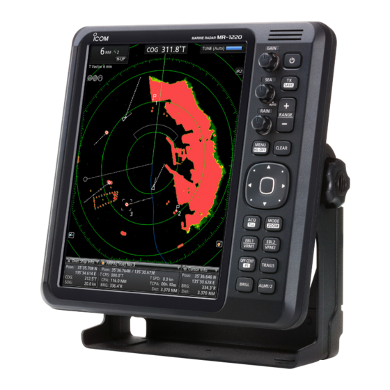
- Page 1 INSTRUCTION MANUAL MARINE RADAR MR-1220 series...
-
Page 2: Table Of Contents
INTRODUCTION Thank you for choosing this Icom product. This product is designed and built with Icom’ s state of the art technology and craftsmanship. With proper care, this product should provide you with years of trouble-free operation. ■ IMPORTANT READ ALL INSTRUCTIONS carefully completely before using the marine radar. -
Page 3: To Detect Sart Signals
United Kingdom, Germany, France, Spain, Russia, radioactive contamination. Australia, New Zealand, and/ or other countries. • The use of Icom radars with any equipment that is All other products or brands are registered trademarks or not manufactured or approved by Icom. -
Page 4: Precautions
INTRODUCTION ■ PRECAUTIONS D For Display unit: The LCD display may have cosmetic imperfections that is displayed as small dark or light spots. This is R WARNING! NEVER let metal, wire or other objects not a malfunction or defect, but a normal characteristic contact the inside of the display unit, or make incorrect of LCD display. - Page 5 INTRODUCTION ■ TABLE OF CONTENTS ■ IMPORTANT............i ADVANCED OPERATION ......... 33 ■ SUPPLIED ACCESSORIES ......i Receiving DSC information ........ 33 ■ FEATURES ............ii TLL function ............34 ■ TO DETECT SART SIGNALS ......ii Displaying your tracks ........35 ■...
-
Page 6: Panel Description
PANEL DESCRIPTION Front panel English keys Chinese keys MR-1220 Function keys (p. 2) Function display (p. 3) 1 [ ] POWER KEY (p. 6) 7 RAIN CONTROL (p. 8) RAIN Push to turn the radar power ON or OFF. Eliminates echoes from rain, snow, fog, and so on. z Rotate the control fully counter clockwise to 2 [TX (SAVE)] / [ ] KEY (pp. - Page 7 PANEL DESCRIPTION Front panel D Function Keys PUSH PAGE HOLD DOWN FOR 1 SECOND PAGE [ACQ (TLL)] ACQUIRE TARGET (TLL)] Acquires an ARPA target under the • Makes a TLL maker under the cursor. p. 29 p. 34 cursor. • Outputs the position data under the cursor to the NMEA output port.
-
Page 8: Function Display
PANEL DESCRIPTION Function display L The screen below is only an example. 2 3 Information boxes 1 SCREEN RANGE READOUT (p. 6) 5 BEARING REFERENCE (p. 10) Displays the range of the current screen. Displays the bearing reference. Nautical miles T: True bearing Kilometers M: Magnetic bearing... - Page 9 PANEL DESCRIPTION Function display 22 FIXED RANGE RINGS (p. 17) 9 RAIN CONTROL ICON (p. 8) Displays the distance at fixed intervals from the Displayed when the RAIN Control function is active. vessel’s own position. The interval distance is 10 REFERENCE INDICATOR (p. 41) indicated by the ring range readout (w). Displayed when the Input Speed Selection is set to L These rings are displayed when the “Brilliance of “Manual”.
-
Page 10: Menu Screen Operation
PANEL DESCRIPTION Menu screen operation Using the context menu You can customize the infrequently changed values or The radar can display a context menu to shortcut to function settings in the Menu screen. frequently used functions, by holding [ENTER]/[ for 1 second. Routes in the Menu screen, setting screen and the L The items in the context menu vary, depending on your operating situation, for example, selected target, display... -
Page 11: Basic Operation
BASIC OPERATION Turning the power ON or OFF The typical boot up operation The image of the radar changes with the influence of D Turning ON the radar such as weather waves or rain, surrounding terrain, 1. Push [ ] to turn ON the radar. bridges and radar interference from other vessels. -
Page 12: Adjusting The Screen Brilliance And Color
BASIC OPERATION Adjusting the screen brilliance and color You can adjust the screen and key backlight according D Selecting the display color to the weather or brightness of surroundings to get You can select the display color from Day (white better viewing. -
Page 13: Adjusting The Radar Reception
BASIC OPERATION Adjusting the radar reception The following is typical operation examples that D Reducing the rain clutter may hinder radar reception (sea clutter, precipitation The rain clutter control eliminates echoes from rain, interference and echoes from other radar). snow, fog, and so on. z Rotate the control fully RAIN... -
Page 14: Selecting A Screen Mode
BASIC OPERATION Selecting a screen mode The radar has 5 display modes. L “(3D)” is displayed while in the 3D view mode. z Push [MODE]/[ ] to select a display mode. Mode Description Display North marker The top of the display indicates your Headline heading. -
Page 15: Reference Settings
BASIC OPERATION Reference settings The radar can accept the bearing input data from D Setting the Bearing type NMEA, N+1, AUX, or COG data format. According to 1. Select “Bearing Type” in the System menu screen, the bearing source, you can set the bearing type in and then push [ENTER]/[ the Initial menu screen. -
Page 16: Changing The Screen View
BASIC OPERATION Changing the screen view You can change the screen view, according to the situation. D 3D view mode Selecting a target in the 3D view You can focus a target by moving the cross-line cursor You can change to the 2D or 3D view in the TX mode. (the gray cross-line at the surface of the PPI area) When you set the “Standby mode”... - Page 17 BASIC OPERATION Changing the screen view D Temporarily zooming the view D Off Center function You can temporarily zoom the view to the cursor The Off Center function is used to enlarge the upward position. view, typically the bow direction display in the Head- 1.
-
Page 18: Magnifying Small Targets
BASIC OPERATION Magnifying small targets Power Save mode To display small targets clearer, the extending Pulse The radar conserves the vessel’s battery power by Width and Echo Stretch functions are effective. entering the Power Save mode. In the Power Save mode, the radar pauses transmitting for the set period of time (6 minutes at D Pulse Width Setting default.) After the timer expires, the radar resumes... -
Page 19: Trail Function
BASIC OPERATION Trail function The trail function memorizes echoes continuously at D Customizing the trail settings constant intervals. This function is useful for watching You can customize the trail settings in the Trail menu. other vessels’ tracks, approximate relative speed, and [MENU]/[ ... -
Page 20: Basic Radar Theory
BASIC OPERATION Basic radar theory Radar finds targets by receiving electromagnetic radiation reflected from large vessels, bridges, or other nearby metal objects. Receiving unwanted reflections from some objects may cause false echoes on screens where the target does not exist. By understanding these phenomena logically and adjusting the radar function appropriately, some of these false echoes can be reduced. - Page 21 BASIC OPERATION Basic radar theory D Minimum range D Target resolution The minimum range of the radar is primarily Target resolution is determined, by the horizontal determined by transmitter pulse length, vertical beam width and transmit pulse width. It can be difficult beam width, and the scanner unit height.
-
Page 22: Distance And Direction Measurements
DISTANCE AND DIRECTION MEASUREMENTS Distance measurement Various way to measure the distance are provided with this radar. L You can set the distance unit to nautical miles (NM), kilometers (km), or statute miles (SM) in the Initial Menu screen (p. 42). TYPE DESCRIPTION Description Reference... - Page 23 DISTaNCE aND DIRECTION MEaSuREMENTS Distance measurement D Checking the bearing and distance from D Using the Parallel Index lines your vessel 1. Hold down [OFF CENT]/[ ] for 1 second ([PI]/ You can check the bearing and distance to a target by •...
-
Page 24: Bearing And Distance Measurement
DISTaNCE aND DIRECTION MEaSuREMENTS Bearing and distance measurement This radar has two sets of Electronic Bearing Lines (EBL) and Variable Range Markers (VRM) to indicate the target direction from your vessel to a target. D Using the EBL and VRM 1. -
Page 25: Advanced Measurements
DISTaNCE aND DIRECTION MEaSuREMENTS Advanced measurements D Measuring the distance and direction between two targets using both Electronic Bearing Lines (EBL) and both Variable Range Markers (VRM), the following advanced measurements can be made. 1. Move the cursor onto a target. 2. -
Page 26: Alarm Function
ALARM FUNCTION Using an Alarm function the radar has an alarm function to protect your vessel When a target comes into (or goes out of) the Guard zone: from collisions. the Alarm function alerts you with an alarm sound and message on the screen if a vessel, •... - Page 27 AlArm function using an Alarm function D Entering the Power Save mode D Setting the Zone alarm type While the Alarm function is active, you can turn off You can select the alarm type in the menu screen. the display while waiting for an alarm, to conserve the Select “Zone Alarm 1”...
-
Page 28: Ais Receiver
AIS RECEIVER About AIS AIS description The Automatic Identification System (AIS) is primarily D Turning the AIS display ON or OFF used for collision-risk management and navigation You can turn the AIS display ON or OFF in the AIS safety. It automatically transmits and receives vessel menu. - Page 29 AIS RECEIVER AIS description 2 AIS information box D Status of the vessel icon Displays the selected AIS target (3) details. Vessels are displayed with triangle icons. The icon vary, depending on the target status. Vector mode AIS Class or Target type MMSI and Name Details icon Icon...
-
Page 30: Ais Operation
AIS RECEIVER AIS operation AIS description D Course and speed vectors D Displaying AIS target details The vector indicates the target’s predicted, true or You can also display the more details on an AIS target relative course and speed. from a context menu. •... - Page 31 AIS RECEIVER AIS operation D Activating a Sleeping target D Adding to the Favorite AIS list 1. Move the cross-line cursor to a sleeping target, You can enter up to 10 frequently referred targets to and then hold down [ENTER]/[ ] for 1 second.
- Page 32 AIS RECEIVER AIS operation D About Lost targets After a specified period of time (see the table below) has elapsed since the last AIS was received from a vessel, it is considered a Lost Target. The “Lost target” icon automatically disappears from the screen 6 minutes and 40 seconds after the vessel becomes “Lost target.”...
-
Page 33: Ais Settings
AIS RECEIVER AIS settings ■ AIS menu Maximum Targets Sets the maximum number of AIS targets that radar You can customize the settings in the AIS menu. displays to between 10 and 100. Slow Warn Function [MENU]/[ ] > AIS Selects whether or not to use the Slow Warn function. -
Page 34: The Simplified Arpa Operation
THE SIMPLIFIED ARPA OPERATION The Simplified ARPA function ARPA operation The simplified Automatic Radar Plotting Aids (ARPA) D Turning the simplified ARPA function function is designed to help prevent a collision with ON or OFF other vessels or landmasses. You can set about the simplified APRA function ON or The radar automatically acquires and plots other OFF in the ARPA menu. - Page 35 ThE sIMPLIFIED ARPA OPERATION ARPA operation D Description of the ARPA display 5 ARPA information box Displays the selected APRA target details in the If the radar has received ARPA information of other information box. vessels or other targets, the icons are displayed as Vector mode shown below.
- Page 36 ThE sIMPLIFIED ARPA OPERATION ARPA operation D ARPA target status D Course and speed vector The vector indicates the target’s predicted, true or ARPA targets are displayed with icons. The icon relative course and speed. vary, depending on the target type or its status. •...
-
Page 37: Arpa Settings
ThE sIMPLIFIED ARPA OPERATION ARPA settings ■ ARPA menu ■ Related settings You can customize the settings in the ARPA menu. D Target menu [MENU]/[ ] > ARPA ] > Target [MENU]/[ ARPA Function You can change the target settings for ARPA sets whether or not to use the Automatic Radar operation. -
Page 38: Advanced Operation
ADVANCED OPERATION Receiving DSC information If an external DSC data is received through the D Customizing the DSC setting NMEA 2 connector, the radar can display the DSC You can customize the DSC display setting in the information of a target on the screen. Menu screen. -
Page 39: Tll Function
ADvANCED OPERATION TLL function Using the TLL (Target Latitude and Longitude) D Clearing a TLL mark function, you can mark up a place on the screen. You 1. Move the cross-line cursor onto a TLL mark you can also output the TLL information to an external want to clear. -
Page 40: Displaying Your Tracks
ADvANCED OPERATION Displaying your tracks Waypoint indication The Plot function tracks your route on the screen. If the received NMEA 0183 data through the NMEA 2 connector includes the Waypoint data, the radar can D Displaying your track plot the Waypoint marker on the screen. To display your vessel’s track, turn ON the “Display D Displaying the Waypoints Own Track”... -
Page 41: Manual Tuning
ADvANCED OPERATION Manual tuning The radar automatically tunes the receiver by default. You can also manually tune the receiver after the radar has started to transmit. [MENU]/[ ] > video > TUNE 1. Open the “video” menu in the Menu screen. 2. -
Page 42: Menu Screen
MENU SCREEN Using the Menu screen You can customize the radar settings infrequently changed values or function settings. Example: Turning the Key Beep ON or OFF ] > System > Key Beep [MENU]/[ 1. Push [MENU]/[ L The menu screen is displayed. The Menu screen disappears 10 seconds after the last operation. -
Page 43: Menu Items
MENU SCREEN Menu items ■ Display ■ Brilliance & Color Number of Echo Steps Display Own Vector Sets the number of echo gradation steps to 8 or 32. Displays or hides your own ship’s vector. L Requires the Bearing and Ship Speed data input. Brilliance of Heading Line PPI Area Setting Sets the brilliance of the heading line to 1 (weak), 2,... -
Page 44: Target
MENU SCREEN Menu items ■ Target Favorite Target List You can enter up to 10 of Favorite targets. Vector Mode Setting ID Blocking Function Selects the vector (speed and bearing) reference of Set whether or not to individually exclude the targets the target. -
Page 45: Video
MENU SCREEN Menu items ■ Video ■ System TUNE Key Beep Sets the tuning method to Auto or Manual. Sets whether or not to sound a beep when a key is “TUNE (Auto)” or “TUNE (Man)” is displayed in the pushed. - Page 46 MENU SCREEN Menu items ■ System (Continued) TLL Mode Selects the action when the [ACQ (TLL)]/[ (TLL)] is Variation held down for 1 second. Selects the difference setting between True North and • Output: Outputs the position information Magnetic North. where the cursor is positioned, to •...
-
Page 47: Initial
MENU SCREEN Menu items ■ Initial TX Inhibit Selects whether or not to pause transmission in a specific zone. When turning ON this function, also set Unit (Distance) the Start Point and Angle settings below. L Settable only in the Standby mode. Start Point (TX Inhibit) Selects the distance unit from NM (nautical miles), km (kilometers), or SM (miles). -
Page 48: Dsc List
MENU SCREEN Menu items ■ DSC List Displays the received DSC logs. z Select an ID from the list to display the details. You can select the target by holding down [ENTER]/[ ] for 1 second in the list, and then pushing [ENTER]/[ ] again. -
Page 49: Nmea Connector (Plt-167-P-R)
INSTALLATION AND CONNECTIONS White title Basic connections CAUTION: • DO NOT turn ON the display unit until both the display unit and the scanner unit are completely installed and connected. • NEVER connect anything other than the supplied scanner unit. •... -
Page 50: Selecting A Location
INSTALLATION AND CONNECTIONS Selecting a location Installing the display unit D Mounting with the bracket D Display unit Install the display unit in a place that meets the The mounting bracket supplied with the display unit following important conditions: enables “dashboard” or “overhead” mounting. 1. - Page 51 INSTALLATION AND CONNECTIONS Installing the display unit D Wall mounting The display unit can be mounted to a flat surface, such as an instrument panel, using the M6 mounting bolts. 1. Remove the 4 screw hole seals from the 4 corners 5.
-
Page 52: Spring Washers (M6)
INSTALLATION AND CONNECTIONS Installing the scanner unit (Radome type) Installing the scanner unit (Radome type) For the SC-R40 radome type scanner unit. D Mounting the scanner unit R WARNING! TURN OFF the display unit whenever your are working with the scanner unit. - Page 53 INSTALLATION AND CONNECTIONS Installing the scanner unit (Radome type) D Connecting the system cable CAUTION: DO NOT cut the supplied system cable. 1. Using a hex head wrench, loosen the 4 bolts on the bottom of the scanner unit, and remove the cover.
-
Page 54: Installing The Scanner Unit (Open Array Types)
INSTALLATION AND CONNECTIONS Installing the scanner unit (Open array types) Installing the scanner unit (Open array types) For the SC-T40, SC-T60, and SC-T60L open array type scanner units. D Mounting the scanner unit R WARNING! TURN OFF the display unit whenever you are working with the scanner unit. -
Page 55: System Cable (20 M)
INSTALLATION AND CONNECTIONS Installing the scanner unit (Open array types) D Wiring the system cable 5. Connect the system cable to the scanner unit. 1. Remove the 4 bolts on the bottom of the scanner 1 Pass the power cables (black and red) of body using the supplied allen wrench (1), and the system cable through the looped cable open the top cover. -
Page 56: Flat Washers (M6)
INSTALLATION AND CONNECTIONS Installing the scanner unit (Open array types) D Attaching the antenna unit 1. Spread the supplied silicon sealant onto the top of 8. Tighten the sealing-nut. the antenna mount. DO NOT install the system cable in tension. It may cause contact failure. -
Page 57: Installing The Ux-234 Video Output Unit
INSTALLATION AND CONNECTIONS Installing the UX-234 Video output unit Installing the UX-234 Video output unit You can connect an external display or a PC monitor with a VGA connector to the display unit by installing an optional UX-234 video output unit The external monitor requires the resolution of 800 ×... -
Page 58: Ferrite Emi Filter
INSTALLATION AND CONNECTIONS Installing the UX-234 Video output unit 7. Connect the UX-234 to the display unit’s connector, then adjust the 4 screw holes. 8. Fix the UX-234 to the display unit tightening the 4 Screw screws supplied with the UX-234. UX-234 Connector Connector... -
Page 59: Maintenance
MAINTENANCE Periodic maintenance Continued, reliable operation of the radar depends on how you care for it. The simple maintenance tips that follow can help you save time and money, and avoid premature equipment failure. R WARNING! TURN OFF the radar before any maintenance. z Keep the equipment as clean as possible. -
Page 60: Error Messages
MAinTenAnCe Error messages An error message is displayed at the bottom or the center of the display, as shown below. Check the connection of the cables or the external data source devices. D MR-1220 error messages Message Condition Check Scanner Connection.* The system cable may not be properly connected. -
Page 61: Settings For A Maintenance
MAinTenAnCe Settings for a maintenance D Selecting the language D Adjusting the heading line You can change the displayed language such as if the heading marker line differs from the actual bow the items in the main screen, the Menu screen, and direction, in such a case the scanner has not been warning messages. - Page 62 MAinTenAnCe Settings for a maintenance D Adjusting the sweep timing D Saving or loading the settings The system cable length affects the sweep timing. The radar can save three different settings for different if a straight target is displayed as a curved echo, operators or different situations, and immediately adjust the “Timing Adjust”...
- Page 63 MAinTenAnCe Settings for a maintenance D Resetting to the defaults When you reconfigure your settings, you can reset the radar settings to the factory defaults. There are 2 types of resetting. Select an appropriate way, according to your situation. • Settings Reset Resets settings other than in the initial menu.
-
Page 64: Specifications
SPECIFICATIONS ■ Display unit (MR-1220) Model MR-1220R4 MR-1220T4 MR-1220T6 MR-1220T6L Scanner unit SC-R40 SC-T40 SC-T60 SC-T60L Display type 12.1 inch TFT color LCD Resolution 800 (H) × 600 (W) dots Minimum range 25 m, 82 ft (at 1/8 NM range) Maximum range 36 NM 48 NM... -
Page 65: Options
SPECIFICATIONS ■ Options • UX-234 • OPC-2339 (for only the SC-R40) video output unit system cable To connect an external display or a PC monitor with To connect the display unit and the scanner unit. a VGA connector. Length: 20 m (65.6 ft) •... -
Page 66: External Data List
SPECIFICATIONS External data list External data list D External data input The following external data is/are required to use each functions of the MR-1220 series. Connector [NMEA 1] * connector [NMEA 2] * connector THS, HDG, HDM, VDM, RMC, GGA, GLL, GNS,... -
Page 67: Open Source Licenses
The user acknowledges and agrees that Icom Inc. shall not or more independent software components; one part is be responsible for any support, details, or explanation of the copyrighted by Icom Inc., and the other is of a third party, or source code. parties. - Page 68 OPEN SOURCE LICENSES - gzdopen is not supported on RISCOS or BEOS. write to the Free Software Foundation, Inc., 59 Temple EXEMPLARY, OR CONSEQUENTIAL DAMAGES (INCLUDING, BUT NOT LIMITED TO, PROCUREMENT Place - Suite 330, Boston, MA 02111-1307, USA. - For PalmOs, see http://palmzlib.sourceforge.net/ OF SUBSTITUTE GOODS OR SERVICES;...
- Page 69 OPEN SOURCE LICENSES Jochen Striepe <jochen@tolot.escape.de> ■ About "ncurses" startup or in documentation (online or textual) provided Reported that GNU Awk 3.1.0 or greater is required. with the package. LICENSE ISSUES Steve Westerbeck <stevow@charter.net> Redistribution and use in source and binary forms, with The OpenSSL toolkit stays under a dual license, i.e.
- Page 70 OPEN SOURCE LICENSES consequences; the authors accept NO LIABILITY for following disclaimer in the documentation and/or other (b) to reproduce, only as part of, or integrated within, damages of any kind. materials provided with the distribution. Authorized Systems and not on a stand alone basis, the Licensed Software;...
- Page 71 OPEN SOURCE LICENSES subject the Licensed Software to an Excluded 5.6, 5.7, 7 and 8 will survive. signatures. License. An Excluded License means any license Section 6. Warranty 8.5 Entire Agreement. This Agreement, including that requires as a condition of use, modification and/ its attachments, constitutes the entire agreement 6.1 Freescale warrants that for the 30 day period or distribution of software subject to the Excluded...
- Page 72 OPEN SOURCE LICENSES or unauthorized uses, you will fully indemnify, you have any questions or require technical assistance, D Credits defend, and hold harmless Freescale, its Affiliates, please contact Freescale. • This product includes “zlib” open source subsidiaries, officers and directors, employees, Microsoft Corporation is a third party beneficiary to this software, and is licensed according to the and distributors from all liability related to such use,...
- Page 73 MEMO...
- Page 74 MEMO...
-
Page 75: Display Mounting Bracket Template
92 mm (3 inch) 62 mm (2 inch) 31 mm inch) -
Page 77: Operating Guide
MR-1220 series OPERATING GUIDE Refer to the Instruction Manual for details about the ARPA, the AIS receiver, and DSC functions. ■ Display information Fixed ring range readout Screen range readout Heading indicator* Mode indicator* Tuning mode indicator Alarm icons Vector indicator... - Page 78 ■ MR-1220 MENU screen operation Menu Menu q Push to enter the Menu screen. w Push to select a menu. Item Item e Push to select an item. r Push to enter the option selection mode. t Push to select an option. Option Option y Push...
-
Page 79: Mr-1220 Menu Screen Operation
INDEX 2D view ........11 3D view ........11 Heading line Off Center ........12 Adjusting ........56 Operating guide ......72 Heading marker ......12 Option .......... 60 Head-line OFF ......12 AIS ..........23 HL-OFF key ......... 12 Favorite list ...... - Page 80 A7521H-1EX Printed in Japan 1-1-32 Kamiminami, Hirano-ku, Osaka 547-0003, Japan © 2019 Icom Inc. Oct. 2019...
Need help?
Do you have a question about the MR-1220 Series and is the answer not in the manual?
Questions and answers