
Subscribe to Our Youtube Channel
Related Manuals for Icom MR-1000TIII


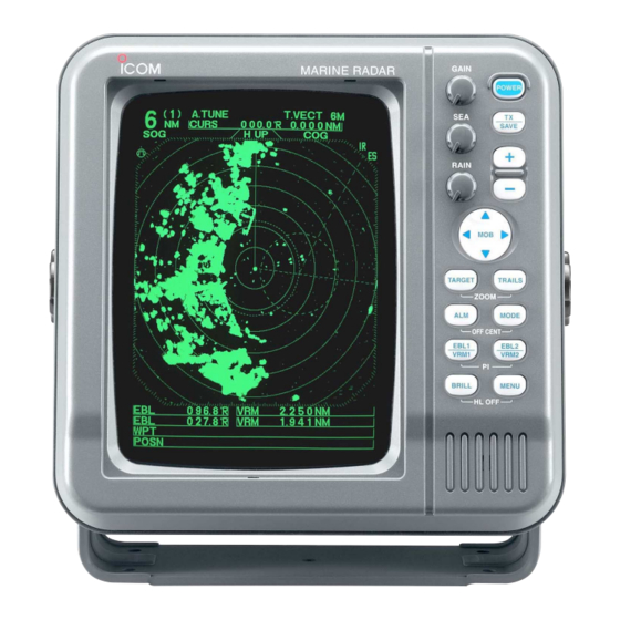
Summary of Contents for Icom MR-1000TIII
- Page 1 INSTRUCTION MANUAL MARINE RADAR MR-1000R™ (Radome type) MR-1000T™ (Open array type; 4 kW) MR-1000T (Open array type; 6 kW)
-
Page 2: System Components
!0 Flat washers (M8) ..........4 !1 Grounding terminal (R5.5-10) ......1 !2 Ferrite bead ............1 Icom, Icom Inc. and the logo are registered trademarks of Icom Incorporated (Japan) in the United states, the United Kingdom, Germany, France, Spain, Russia and/or other countries. -
Page 3: Foreword
If you have any questions regarding the operation of or any other liquids. the radar, contact your nearest authorized Icom Inc. dealer. NEVER connect the radar to AC or more than 42 V DC. -
Page 4: Table Of Contents
TABLE OF CONTENTS SYSTEM COMPONENTS.......... i 8 BASIC RADAR THEORY ......21– 23 I Side-lobe echoes ..........21 SUPPLIED ACCESSORIES........i I Indirect echoes ..........21 FOREWORD ............ii I Multiple echoes ..........22 IMPORTANT ............. ii I Minimum range ..........22 EXPLICIT DEFINITIONS .......... -
Page 5: Caution
CAUTION The MR-1000RII/TII/TIII are supplemental aids to navigation and are not intended to be a sub- stitute for accurate and current nautical charts. DANGER! HIGH VOLTAGE • NEVER OPEN THE UNIT This product contains high voltage that could be FATAL. This product has no user-service- able parts inside. -
Page 6: Panel Description
PANEL DESCRIPTION I Front panel GAIN POWER MARINE RADAR GAIN SAVE POWER SAVE RAIN RAIN TARGET TRAILS ZOOM MODE OFF CENT EBL1 EBL2 VRM1 VRM2 BRILL MENU TARGET TRAILS HL OFF ZOOM MODE OFF CENT EBL1 EBL2 VRM1 VRM2 BRILL MENU HL OFF Control panel (English) - Page 7 PANEL DESCRIPTION o EBL2 (VRM2) SWITCH [EBL2 (VRM2)] !6 MAN OVERBOARD [MOB]/[ ] (pgs. 15–16) Push to mark the man overboard point on the Push to display the electronic bearing line 2 (EBL2) screen. When a crew member falls overboard, push and the variable range marker 2 (VRM2), and acti- [MOB]/[ ] for 1 sec.
-
Page 8: I Screen
PANEL DESCRIPTION I Screen M . TUNE (0.25) MTUNE TVECT 6M TRAILS NM CURS 0174˚R 0649NM H UP HDG2530˚T STW157KT COMPASS ZOOM EBL1 1076˚R VRM1 0422NM EBL2 0219˚R VRM2 0242NM 2834˚R 0632NM CURS 34˚ 39720N 135˚ 34420E @1 TUNING LEVEL INDICATOR (p. 9) @9 MODE INDICATOR Shows the receiver tuning level. - Page 9 PANEL DESCRIPTION #5 COMPASS INDICATOR (pgs. 24, 39) $4 IR INDICATOR (p. 11) • GYRO : NMEA (gyro) is connected. Eliminates or reduces interference caused by other • COMPASS : NMEA (compass), N+1 or AUX data is radar operating nearby. connected.
-
Page 10: Menu
MENU I VIDEO I FUNCTION VIDEO MENU FUNCTIONMENU TUNE AUTO MANUAL RING D.RANGE NAR. MID. WIDE POSN DISP SHIP CURS DIST UNIT STRETCH TRUE PULSE EBL/PI TRUE ˚ PT/SB ZONE ALARM TRAIL TIME BEEP D TUNE D RING • AUTO : Automatic tuning. -
Page 11: I Ata (Automatic Tracking Aid)
MENU I ATA (Automatic Tracking Aid) I INT. SETTING A T A MENU INT. SETTING A T A MAG VAR AUTO MANUAL No.DISP ˚ TRUE VECT BRG INPUT NMEA OWN VECT SPD INPUT ALARM TX INH START ˚ CPA LIMIT 1.0NM TX INH ANGLE ˚... -
Page 12: Basic Operation
BASIC OPERATION I Checking the installation D Checklist Before turning the power ON, be sure all the connec- tions are complete. The checklist at right may be help- q The 4 bolts securing the scanner unit must be firmly ful for necessary confirmation. tightened. -
Page 13: I Basic Operation
BASIC OPERATION I Basic operation q Turn the power ON. GAIN w Push [TX]/[ ] after the countdown disap- POWER pears from the screen. • See “Turning power ON/OFF” on page at left. SAVE e Push [+]/[ ] or [–]/[ ] several times to se- lect the display range. -
Page 14: I Rain Function
BASIC OPERATION The following are typical basic operation examples, which may hinder radar reception (sea clutter, precipitation in- terference and echoes from other radar). I RAIN function This function eliminates reflection echoes from rain, snow, fog etc. • Rotate the control fully counterclockwise to deactivate the control function. -
Page 15: I Ir Function
BASIC OPERATION I IR function Radar interference may appear when another ship’s radar is operating on the same frequency band in close proximity. The IR function can eliminate this type of interference. (p. 6) q Push [MENU]/[ ] to call up VIDEO menu. w Push [ ] until the “IR”... -
Page 16: I Trails Function
BASIC OPERATION I TRAILS function The trails function memorizes echoes continuously or • Setting the trail interval time q Push [MENU]/[ at constant intervals. This is useful for watching other ] to call up the VIDEO menu. ships’ tracks, approx. relative speed, etc. •... -
Page 17: I Ship Speed Indication
BASIC OPERATION I Ship speed indication I Long pulse function When the ship speed data with NMEA 0183 format is To magnify the blips for easier viewing of small targets, applied, the radar can display the ship speed. Knots the long pulse and echo stretch (p. 11) functions are (KT) or kilometers/hour (KM/h) are automatically se- available. -
Page 18: Distance And Direction Measurements
20 1 NOTE: When the screen is shifted, the number of rings may differ. † *Available for the MR-1000TII/TIII. Available for the MR-1000TIII only. D Using the variable range marker q Push [EBL1 (VRM1)]/[ ] to display the VRM1 and EBL1; then, push [ •... -
Page 19: I Bearing And Distance Measurement
DISTANCE AND DIRECTION MEASUREMENTS I Bearing and Distance measurement This radar has 2 Electronic Bearing Lines (EBL) to in- dicate the target direction from your ship or a target. D Using the EBL and VRM q Push [ to move the cursor on the desired TVECT 3M NM CURS 3240R... -
Page 20: I Advanced Measurements
DISTANCE AND DIRECTION MEASUREMENTS I Advanced measurements Using both Electronic Bearing Lines (EBL) and both Variable Range Markers (VRM), the following ad- vanced measurements can be made: D Measuring the distance and direction between 2 targets q Push [ to move the cursor on the desired MTUNE TVECT 3171ßM... -
Page 21: Alarm Function
ALARM FUNCTION The unit has an alarm function to protect your ship from collisions. If other ships or islands, etc. come into the pre- programmed alarm zone, the function alerts you with an alarm. You can set the desired range and bearing for an alarm zone. -
Page 22: Ata (Automatic Tracking Aid)
ATA (Automatic Tracking Aid) I ATA (Automatic Tracking Aid) By tracking automatically the target chosen by the cursor key, the closest point of approach (CPA) and the time to closest point of approach (TCPA) limit of a own ship and a target are calculated. ATA is the function to tell about to alarm sound, when both CPA and TCPA becomes below a setting value (the ap- proach watch area). -
Page 23: I Ata Operation
ATA (Automatic Tracking Aid) I ATA operation Select the target which you want to track on the dis- play. q Push [ to move the “+” cursor on the de- DIST sired target. TCPA w Push [ ] for 1 sec. to select the tar- get for tracking. -
Page 24: I Plots
I Plots Plot displays past position of targets every 1 min. as 3 dots. q Target goes straight. w Target turns right. e Target reduces speed r Target increases speed. -
Page 25: Basic Radar Theory
BASIC RADAR THEORY Radar uses a form of electromagnetic radiation, which like light, can be reflected. Because of this property, some objects may cause false echoes on the screen where in fact no targets actually exist. These echoes may appear if a large vessel, bridge, or tank is in proximity. Operators should be familiar with the ef- fects of these phenomena. -
Page 26: I Multiple Echoes
BASIC RADAR THEORY I Multiple echoes Multiple echoes may appear when a short-range and Multiple echoes will appear beyond the target’s true strong echo is received from a ship, bridge, or break- echo point on the same bearing of a large target. They water. -
Page 27: I Blind And Shadow Sectors
BASIC RADAR THEORY I Blind and Shadow sectors Blind or Shadow sectors may exist because of ob- When tall and massive targets such as a large island structions such as masts, derricks or stacks. An ob- are located at close range also shadowed without pro- struction may throw either a complete or partial ducing any echoes. -
Page 28: Installation And Connections
INSTALLATION AND CONNECTIONS I Connecting the units Power supply 10.2 to 42 V DC Black: _ Red: Supplied scanner unit NEVER connect any- thing other than the sup- plied scanner unit. Ground NMEA2: NMEA1: NMEA 0183 data input Bearing data input Speed sensor input NMEA1 connection NMEA2 connection... -
Page 29: I Installing The Display Unit
INSTALLATION AND CONNECTIONS I Installing the display unit D Location D Mounting Select a place for installation which meets the following The mounting bracket supplied with the display unit al- important conditions: lows “dashboard” or “overhead” mounting. q The display unit should be placed near the wheel in q Hold the mounting bracket up to the selected loca- the cabin so that an operator may easily view the tion and mark pilot holes for the 5 installation holes... -
Page 30: I Mounting The Ex-2714 Scanner Unit
INSTALLATION AND CONNECTIONS I Mounting the EX-2714 scanner unit D Location D Mounting WARNING: BE SURE [POWER] is OFF when- q Drill four holes of 12 mm ( ⁄ in) in diameter using ever you are working with the scanner unit. the template. -
Page 31: I Wiring The Ex-2714 System Cable
INSTALLATION AND CONNECTIONS I Wiring the EX-2714 system cable CAUTION: NEVER cut the supplied system cable. y Connect the power cable (black and red) end to the q Loosen the four bolts using a hex head wrench on power unit connector. (*2; Be sure to follow the fol- the bottom of the scanner unit, and open the unit. -
Page 32: I Mounting The Ex-2780 Scanner Unit
INSTALLATION AND CONNECTIONS I Mounting the EX-2780 scanner unit • Location • Mounting q Drill four (4) holes of 12 mm ( ⁄ in) in diameter WARNING: BE SURE [POWER]/[ ] is using the template. OFF whenever you are working with the scanner w If the mounting surface or platform is metal, apply unit. -
Page 33: I Wiring The Ex-2780 System Cable
INSTALLATION AND CONNECTIONS I Wiring the EX-2780 system cable CAUTION: NEVER cut the supplied system cable. q Loosen the four bolts using the supplied hex head wrench on the bottom of the scanner unit, and open the unit. (Fig. 1) w Loosen the nut on the scanner unit and pass the system cable through the nut and sealing tube. -
Page 34: I Fixing The Ex-2780 Scanner Unit
INSTALLATION AND CONNECTIONS I Fixing the EX-2780 scanner unit q Put the scanner unit* NOTE: When using the optional system cable. on the stay, then fix the an- tenna rotor with installation bolts of 8 mm (5/16 in) Peel the outer sheath of the system cable when using in diameter, with flat and dish washers and a seal- the optional system cable OPC-1078A. -
Page 35: Other Functions
OTHER FUNCTIONS D Antenna rotation speed The antenna rotation speed can be selected from 48 rpm and 36 rpm. (Default: 48 rpm) Pushing and holding [–]/[ ] for 1 sec. to select 36 rpm rotation speed, pushing and holding [+]/[ for 1 sec. -
Page 36: Service Man Menu
, 72 † : Choose the selectable screen range. w Push [ *MR-1000TII/TIII † MR-1000TIII only [MENU]/[ “SERVICE MAN” D SETUP MEMORY menu. • The present setting value is displayed by pushing [ ], then select the desired item from “RECALL” and “SAVE”... -
Page 37: I Timing Adjustment
SERVICE MAN MENU I TIMING adjustment e Push [TX (SAVE)]/[ The system cable length affects the sweep timing. ] to display the target When the cable length adjustment is not correct, a on the screen. r Push [MENU]/[ straight target is shown as a curved echo. Thus, cable ], [ ] and [ ] several times to length adjustment is necessary. -
Page 38: I Spd Adjustment
, 1, 1.5, 2, 3, 4, 6, 8, 12, 16, 24, 32, 36, 48*, 64 † , 72 † (NM) *48 NM range is available for the MR-1000TII/TIII. † 64 and 72 NM ranges are available for the MR-1000TIII only. -
Page 39: Error Message
ERROR MESSAGE I Error message list Message Condition BRG INPUT FAIL* • The Azimuth signal is interrupted. An alarm tone is emitted within 5 sec. and the display reverts to H UP mode in approx. 1 min. TRIG SIGNAL FAIL* •... -
Page 40: Maintenance
MAINTENANCE Continued, reliable operation of the radar depends on how you care for your equipment. The simple maintenance tips that follow can help you save time and money, and avoid premature equipment failures. I Periodic maintenance q Keep the equipment as clean as possible. WARNING: BE SURE the power is OFF before •... -
Page 41: Specifications
, 1, 1.5, 2, 3, 4, 6, 8, 12, 16, 24, 32, 36, 48*, † , 72 † (NM) *MR-1000TII/TIII, † MR-1000TIII only • Preheat time : 90 sec. • Connection length between display and scanner unit : 15 m; 49 ⁄ (MR-1000RII) 20 m; 65 ⁄... - Page 42 : 10.2 to 42 V DC • Power consumption (at wind velocity zero) : Approx. 60 W (MR-1000RII) Approx. 70 W (MR-1000TII) Approx. 80 W (MR-1000TIII) • Usable temperature range : –15˚C to +55˚C; +5˚F to 131˚F • Relative humidity : Less than 95% at 35˚C (+95˚F)
-
Page 43: External Data List
EXTERNAL DATA LIST The following external bearing, speed, position and way point data is (are) required , when you use the radar func- tions. EXTERNAL DATA INPUT NMEA1* NMEA2* “HDT”, “HDM” “RMC”, “GGA”, “GLL”, “VTG”, “WPL”, “BWC”, LOG, “GNS” N+1, AUX FUNCTION DISPLAY BEARING... - Page 44 100 mm (3 ⁄ 60 mm (2 ⁄ 30 mm (1 ⁄...
- Page 45 • EX-2714 Radome template 45.5 mm (1 ⁄ 150.5 mm (5 ⁄ Radius is 6 mm ⁄ 90.5 mm (3 ⁄ Ship’s bow direction 90.5 mm (3 ⁄...
- Page 46 •EX-2780 Open array type Radius is 6 mm ⁄ in). template 190 mm (7 ⁄ 131 mm (5 ⁄ Ship’s bow direction 131 mm (5 ⁄...
- Page 47 A-6317H-1EX-r Printed in Japan © 2003–2007 Icom Inc. 1-1-32 Kamiminami, Hirano-ku, Osaka 547-0003, Japan Printed on recycled paper with soy ink.
Need help?
Do you have a question about the MR-1000TIII and is the answer not in the manual?
Questions and answers