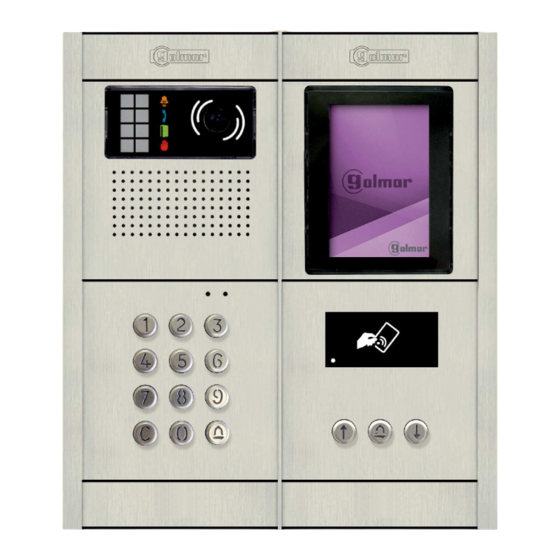
golmar Nexa Modular GB2 User Manual
2-wire audio and video door entry system coded panel
Hide thumbs
Also See for Nexa Modular GB2:
- User manual (44 pages) ,
- Quick manual (13 pages) ,
- User manual (20 pages)

Subscribe to Our Youtube Channel
Related Manuals for golmar Nexa Modular GB2


Summary of Contents for golmar Nexa Modular GB2
- Page 1 TECHNOLOGY Nexa Modular GB2 2-Wire Audio and Video Door Entry System Coded Panel Code 50122371 TCODE/CA GB2 EN REV.0 17...
-
Page 2: Table Of Contents
40cm away from any other wiring Before connecting the device to the mains, check the connections between the door panel, power supply unit, distributors, camera interface, GSM interface, monitors, telephones and hands-free audio terminals. Use the Golmar RAP-2150 cable (2x1mm ). -
Page 3: Safety Precautions
G 2 AUDIO AND VIDEO DOOR ENTRY SYSTEM - CODED PANEL SAFETY PRECAUTIONS Always disconnect the power supply before installing or making modifications to the devices. The fitting and handling of these devices must be carried out by authorised personnel The wiring must run at least 40 cm away from any other wiring. -
Page 4: Description Of The Door Panel
G 2 AUDIO AND VIDEO DOOR ENTRY SYSTEM - CODED PANEL DESCRIPTION OF THE DOOR PANEL Description of the Nexa modular door panel: Door panel component assembly drawing. Electronic modules Embedding boxes Frame module Aluminium panel Description of the door panel. Fixing screws for endpieces (x8) Fixing screws for embedding box (x2) Clip-on covers: 60xx... -
Page 5: Description Of The El632/Gb2A Sound Module
Do not use (internal use). Button number. Terminal strip connector (GB2 Bus). Connection terminals: Positive, negative (12Vdc output for Golmar DC electric lock). Contact 'C' for electric lock (Relay 1). Contact 'NO' for electric lock (Relay 1). AP ,AP+ Input for exterior door opening button (Relay 1). -
Page 6: Description Of The Sound Module Dip Switch
G 2 AUDIO AND VIDEO DOOR ENTRY SYSTEM - CODED PANEL DESCRIPTION OF THE SOUND MODULE Description of the sound module DIP switch: The DIP switch is located on the left side of the back of the module. Door panel address: DIP switches: 1 and 2 OFF (address 1), 1 ON and 2 OFF (address 2), 1 OFF and 2 ON (address 3), 1 and 2 ON (address 4). -
Page 7: Description Of The Vocal Synthesis (Audible Signals On The Door Panel)
G 2 AUDIO AND VIDEO DOOR ENTRY SYSTEM - CODED PANEL DESCRIPTION OF THE SOUND MODULE Description of the vocal synthesis (audible signals on the door panel): Audible signals on the door panel. If vocal synthesis is enabled on the sound module (see page 19 and 21 for configuration), the following voice messages can be heard on the door panel: While calling: 'Call is in progress'. - Page 8 G 2 AUDIO AND VIDEO DOOR ENTRY SYSTEM - CODED PANEL DESCRIPTION OF THE SOUND MODULE Selecting the sound module operating mode: Continued from previous page Building mode: Set DIP 4 on the sound module to ON (see page ). Up to 23 monitors and apartments with a Vesta2 monitor per installation.
-
Page 9: Description Of The Tft El3422/Gb2 Screen Module
G 2 AUDIO AND VIDEO DOOR ENTRY SYSTEM - CODED PANEL DESCRIPTION OF THE TFT SCREEN MODULE Description of the EL3422/GB2 TFT screen module: Front. TFT screen. Back. Socket for connection with the EL632/GB2A. Note: See its connections (page 15). -
Page 10: Description Of The Tk3401/Gb2 Proximity Key Kit
G 2 AUDIO AND VIDEO DOOR ENTRY SYSTEM - CODED PANEL DESCRIPTION OF THE PROXIMITY ACCESS CONTROL MODULE Description of proximity reader modules N3401/GB2 and NX3401/GB2: Front. Proximity key reader. Bell button. Selection buttons. Back. Socket for connection with the EL632/GB2A module. Note: See its connections (page 15). -
Page 11: Description Of The N3301/Gb2 And Nx3301/Gb2 Keypad Access Control Module
G 2 AUDIO AND VIDEO DOOR ENTRY SYSTEM - CODED PANEL DESCRIPTION OF THE KEYPAD ACCESS CONTROL MODULE Description of the N3301/GB2 and NX3301/GB2 keypad access control module Front. Numeric keypad. Bell button. Cancel button. Back. Socket for connection with the EL632/GB2. Terminal strip connector for 22 Vdc output. -
Page 12: Description Of The El3002H/Gb2 Auditory Accessibility Module
G 2 AUDIO AND VIDEO DOOR ENTRY SYSTEM - CODED PANEL DESCRIPTION OF THE AUDITORY ACCESSIBILITY MODULE Description of the EL3002H/GB2 auditory accessibility module: Front. Communication active LED. Back. Socket for connection with the EL632/GB2A. Terminal strip connector for 12 Vac power supply. Connection terminals: 12 Vac power input (Only required if EL610D modules exist) Note: See its connections (page 15). -
Page 13: Description Of The El3002 Illumination Module
G 2 AUDIO AND VIDEO DOOR ENTRY SYSTEM - CODED PANEL DESCRIPTION OF THE ILLUMINATION MODULE Description of the EL3002 illumination module Front. LED illumination panel. Back. NEXA Bus connectors. (Do not connect to GB2 system) Terminal strip connector for 12 Vac power supply. Connection terminals: 12 Vac power input Note: See its connections (page 15). -
Page 14: Installation Of The Door Panel
G 2 AUDIO AND VIDEO DOOR ENTRY SYSTEM - CODED PANEL INSTALLATION OF THE DOOR PANEL Preparing the cable entry: Break the flange to allow entry of cables through the bottom part of the embedding box. In the case of door panels with more than one embedding box, break through the side holes and join the embedding boxes using cable grommets. -
Page 15: Fastening The Frame To The Embedding Box
G 2 AUDIO AND VIDEO DOOR ENTRY SYSTEM - CODED PANEL INSTALLATION OF THE DOOR PANEL Fastening the frame to the embedding box: Insert the spring hinge which attaches to the product in the embedding box, as shown in the drawing. To fasten the frame to the embedding box, insert the spring hinge into the housings provided for this purpose in the frame, as shown in the drawing. -
Page 16: Closing The Door Panel
G 2 AUDIO AND VIDEO DOOR ENTRY SYSTEM - CODED PANEL INSTALLATION OF THE DOOR PANEL Closing the door panel: Fix the door panel to the embedding box using the screws supplied. To complete the fitting of the panel, attach the clip-on covers by positioning one end and then applying slight pressure to the other end until they clip into place. -
Page 17: Installation Of The Lock Release
DIN-963 IMPORTANT: The lock release must be 12V DC or AC (Golmar). (See page 38 for a.c. lock release and page 35-37 for d.c. lock release). The sound module is supplied with two varistors. If connecting an AC lock release to one of the outputs, fit the varistor supplied directly to the lock release terminals to ensure the device functions correctly. -
Page 18: Programming Of The Door Panel
G 2 AUDIO AND VIDEO DOOR ENTRY SYSTEM - CODED PANEL PROGRAMMING THE DOOR PANEL Programming mode entry and exit: To enter programming mode, press the bell button (N3301/GB2), followed by the administrator code '1234', and finally confirm by pressing the bell button (N3301/GB2) again. 'bell (N3301/GB2)' + 'administrator code' + 'bell (N3301/GB2)'. -
Page 19: Programming Fields
G 2 AUDIO AND VIDEO DOOR ENTRY SYSTEM - CODED PANEL PROGRAMMING THE DOOR PANEL Programming fields: The module is pre-programmed with factory settings except for the activation codes, which are left empty for security reasons. For system operation tailored to the needs of the user, check the values set in all of the fields. The fields do not need to be programmed in numerical order. - Page 20 G 2 AUDIO AND VIDEO DOOR ENTRY SYSTEM - CODED PANEL PROGRAMMING THE DOOR PANEL Programming fields: Continued from previous page Field '03': Sets relay activation time. Enables the setting of an activation time for Relay 1 and Relay 2 between 1 and 99 seconds. Steps: Field + bell (N3301/GB2) + activation time + bell (N3301/GB2).
- Page 21 G 2 AUDIO AND VIDEO DOOR ENTRY SYSTEM - CODED PANEL PROGRAMMING THE DOOR PANEL Programming fields: Continued from previous page Field '06': Resets the administrator code to the factory setting and clears all access codes. Enables the resetting of the administrator code to factory setting 1234 and the clearing of all access codes. Steps: Field + bell (N3301/GB2) + administrator code + bell (N3301/GB2).
- Page 22 G 2 AUDIO AND VIDEO DOOR ENTRY SYSTEM - CODED PANEL PROGRAMMING THE DOOR PANEL Programming fields: Continued from previous page Field '11': Volume of the sound module speaker in communication. Enables the setting of the speaker volume of the sound module in communication. Steps: Field + bell (N3301/GB2) + sound module volume level + bell (N3301/GB2).
- Page 23 G 2 AUDIO AND VIDEO DOOR ENTRY SYSTEM - CODED PANEL PROGRAMMING THE DOOR PANEL Programming fields: Continued from previous page Field '13': maximum intensity level of the illumination LEDs for the camera. Indicates the intensity level of the illumination LEDs for the camera. Steps: Field + bell (N3301/GB2) + intensity + bell (N3301/GB2).
- Page 24 G 2 AUDIO AND VIDEO DOOR ENTRY SYSTEM - CODED PANEL PROGRAMMING THE DOOR PANEL Programming fields: Continued from previous page Field '19': Sets the temporary access code for Relay 2. Enables the assignment of a temporary access code to activate Relay 2. Steps: Field + bell (N3301/GB2) + Relay 2 access code + bell (N3301/GB2).
- Page 25 G 2 AUDIO AND VIDEO DOOR ENTRY SYSTEM - CODED PANEL PROGRAMMING THE DOOR PANEL Programming fields: Continued from previous page Field '60-99': Sets the access code for Relay 2. Enables the storage of an access code to activate Relay 2. Up to 40 codes can be assigned for this relay. Steps: Field + bell (N3301/GB2) + Relay 2 access code + bell (N3301/GB2).
-
Page 26: Programming Fields Summary
G 2 AUDIO AND VIDEO DOOR ENTRY SYSTEM - CODED PANEL PROGRAMMING THE DOOR PANEL Programming fields: The following table shows a summary of the programming fields available, the possible values that the programming fields can take by using the N3301/GB2 keypad and the default settings. DEFAULT DESCRIPTION OF THE PROGRAMMING... -
Page 27: Managing Proximity Keys
G 2 AUDIO AND VIDEO DOOR ENTRY SYSTEM - CODED PANEL PROGRAMMING THE DOOR PANEL Managing proximity keys: For resident proximity key access and management, the system must have an N3401/GB2 proximity access control module. TK3401/GB2 key kit not included IMPORTANT: It is necessary to initially activate the MASTER CARD ADD and MASTER CARD DELETE keys on the door panel to be managed before resident keys can be added/deleted... - Page 28 G 2 AUDIO AND VIDEO DOOR ENTRY SYSTEM - CODED PANEL PROGRAMMING THE DOOR PANEL Managing proximity keys: For resident proximity key access and management, the system must have an N3401/GB2 proximity access control module. TK3401/GB2 key kit not included IMPORTANT: It is necessary to initially activate the MASTER CARD ADD and MASTER CARD DELETE keys on the...
- Page 29 G 2 AUDIO AND VIDEO DOOR ENTRY SYSTEM - CODED PANEL PROGRAMMING THE DOOR PANEL Managing proximity keys: Continued from previous page Deleting all resident proximity keys: Hold the MASTER CARD DELETE key near to the N3401/GB2 proximity reader, communication (Step 1) indicator will illuminate and the door panel will emit a long and then short tone to indicate that it is in...
-
Page 30: Managing The Apartment List
The apartment list can be created using the 'Address Manager GB2' program, available for download from https://doc.golmar.es. By means of 'Address Manager GB2', it is also possible to reassign the terminal to which buttons 1 and 2 of the EL632/GB2A module and the buttons of the EL610D modules, if any, make the call. - Page 31 G 2 AUDIO AND VIDEO DOOR ENTRY SYSTEM - CODED PANEL PROGRAMMING THE DOOR PANEL Managing the apartment list: Continued from previous page Then double-click on the list of the door panel to be modified to show its information, DIP switch (Paso 4) configuration, operating mode and available modules.
- Page 32 G 2 AUDIO AND VIDEO DOOR ENTRY SYSTEM - CODED PANEL PROGRAMMING THE DOOR PANEL Managing the apartment list: Continued from previous page To assign a contact to a button on the EL632/GB2A module, click on the corresponding button in the (Step 6A) module window, and a new window will be displayed.
- Page 33 G 2 AUDIO AND VIDEO DOOR ENTRY SYSTEM - CODED PANEL PROGRAMMING THE DOOR PANEL Managing the apartment list: Continued from previous page Once the apartment list entries has been edited, the list will be displayed. It can be edited by double (Step 8) clicking on the contact to change it if any detail is not correct.
-
Page 34: Managing The Apartment List
G 2 AUDIO AND VIDEO DOOR ENTRY SYSTEM - CODED PANEL PROGRAMMING THE DOOR PANEL Managing the apartment list: Continued from previous page Transferring contacts list and configuring buttons on the EL632/GB2A module: With DIP 6 of the EL632/GB2A module in the OFF position, disconnect the power supply (Step 1) of the EL632/GB2A module. -
Page 35: Wiring Diagrams
G 2 AUDIO AND VIDEO DOOR ENTRY SYSTEM - CODED PANEL WIRING DIAGRAMS Video door entry system with 23 VESTA2 monitors, 12 D2L-GB2 distributors and Golmar DC lock release. VESTA2 Master End of line ( ) 3 APARTMENT VESTA2 VESTA2... - Page 36 G 2 AUDIO AND VIDEO DOOR ENTRY SYSTEM - CODED PANEL WIRING DIAGRAMS Audio door entry system with 128 apartments/NHEA hands-free audio terminals and Golmar DC lock release: (The EL632 GB2A sound module should be set to 'operating mode 2 and 6' audio only, see pp. 7 and 8).
- Page 37 G 2 AUDIO AND VIDEO DOOR ENTRY SYSTEM - CODED PANEL WIRING DIAGRAMS Video door entry system with 4 access panels, DP-GB2A distributor for door panels and Golmar DC lock release. Video door entry system: To the distributors (building floors)
- Page 38 G 2 AUDIO AND VIDEO DOOR ENTRY SYSTEM - CODED PANEL WIRING DIAGRAMS Connection of Golmar DC and AC lock releases. Connection of 2 DC lock releases without 'AP': Access panel To the FA-GB2/A power supply C1 NA1 C2 AP+ AP- P1 P2 BUSBUS...
-
Page 39: Wiring Diagrams
G 2 AUDIO AND VIDEO DOOR ENTRY SYSTEM - CODED PANEL WIRING DIAGRAMS Connection of the EL3002H/GB2 auditory accessibility module. Connection of the EL3002H/GB2 module If the door panel has an N3301/GB2 or NX3301/GB2 module, it will not be necessary to power the EL3002H/GB2 module with an additional TF-104, as shown in the following diagram. - Page 40 C/ Silici, 13 08940- Cornellá de Llobregat SPAIN Golmar se reserva el derecho a cualquier modificación sin previo aviso. Golmar se réserve le droit de toute modification sans préavis. Golmar reserves the right to make any modifications without prior notice.
Need help?
Do you have a question about the Nexa Modular GB2 and is the answer not in the manual?
Questions and answers