golmar GB2 Nexa Modular User Manual
Hide thumbs
Also See for GB2 Nexa Modular:
- User manual (44 pages) ,
- Quick manual (13 pages) ,
- Quick manual (12 pages)

Related Manuals for golmar GB2 Nexa Modular


Summary of Contents for golmar GB2 Nexa Modular
- Page 1 Video door entry system 2 wires installation GB2 Nexa Modular Cod. 50121878 T632 GB2 EN REV.0315...
-
Page 2: Table Of Contents
VIDEO DOOR ENTRY SYSTEM GB2 NEXA MODULAR - BUILDING INTRODUCTION First of all we would like to thank and congratulate you for the purchase of this product. The commitment to reach the satisfaction of our customers is stated through the ISO-9001 certification and for the manufacturing of products like this one. -
Page 3: Safety Precautions
VIDEO DOOR ENTRY SYSTEM GB2 NEXA MODULAR - BUILDING SAFETY PRECAUTIONS - Install or modify the equipment, without the power connected. - The installation and handling of these equipments must be performed by authorised personnel. - The entire installation must be at least 40 cm. away from any other installation. -
Page 4: Door Panel Description (Nexa Modular)
VIDEO DOOR ENTRY SYSTEM GB2 NEXA MODULAR - BUILDING DOOR PANEL DESCRIPTION (NEXA MODULAR) Door panel description: General detail of parts, for assembly the door panel. Electronic Embedding boxes Frame modules Aluminium door panel modules Door panel description. Screws of fixation of header (x4) -
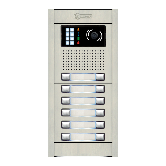
Page 5: Sound Module Description (El632-Gb2)
VIDEO DOOR ENTRY SYSTEM GB2 NEXA MODULAR - BUILDING SOUND MODULE DESCRIPTION (EL632/GB2) Sound module description (EL632/GB2): Front side. Color camera. Leds (visual indications for people with impaired hearing). Leds (environment low luminosity). Speaker. Microphone. Sound module push buttons (x2). -
Page 6: Push Buttons Module Description (El610D)
VIDEO DOOR ENTRY SYSTEM GB2 NEXA MODULAR - BUILDING PUSH BUTTONS MODULE DESCRIPTION (EL610D) Push buttons module description (EL610D): Front side. Push buttons module (x10). Back side. Input / output push buttons connector (x3). Configuration dip switch (Push buttons call code). -
Page 7: Embedding Box Positioning
VIDEO DOOR ENTRY SYSTEM GB2 NEXA MODULAR - BUILDING DOOR PANEL INSTALLATION Embedding box positioning: 1850 1650 1450 The upper part of the door panel should be placed at 1,65m. height roughly. The hole dimensions will depend on the type of door panel. -
Page 8: Place The Embedding Box
VIDEO DOOR ENTRY SYSTEM GB2 NEXA MODULAR - BUILDING DOOR PANEL INSTALLATION Place the embedding box: Pass the wiring through the hole made in the bottom part of the embedding box. Level and flush the embedding box. Once the embedding box is placed, remove the protective labels from the attaching door panel holes. -
Page 9: Hold The Frame
VIDEO DOOR ENTRY SYSTEM GB2 NEXA MODULAR - BUILDING DOOR PANEL INSTALLATION Hold the frame on the embedding box: Insert the hinge that it is supplied with the product in the embedding box, as shown in the drawing. To hold the frame on the embedding box, insert the hinge in the housings arranged for this purpose in the frame, as shown in the drawing. -
Page 10: Plug The Push Buttons With The Connection Cable Rap-610D
VIDEO DOOR ENTRY SYSTEM GB2 NEXA MODULAR - BUILDING DOOR PANEL INSTALLATION Plug the push buttons with the connection cable RAP-610D: Use the connection cable RAP-610D, for the connection of the push buttons between the sound module and the push buttons module EL610D and between push buttons modules EL610D, when the distance between modules to connecting is greater due to the composition of the door panels. -
Page 11: Double Push Button Module Coding
VIDEO DOOR ENTRY SYSTEM GB2 NEXA MODULAR - BUILDING DOOR PANEL INSTALLATION Double push button module coding: EL632/GB2 C1 NA1 C2 AP+ AP- P1 P2 BUSBUS Relé 1 Relé 2 12Vdc Code 1 Code 0 Code 1 EL610D Code 10... - Page 12 VIDEO DOOR ENTRY SYSTEM GB2 NEXA MODULAR - BUILDING DOOR PANEL INSTALLATION Single push button module coding: EL632/GB2 C1 NA1 C2 AP+ AP- P1 P2 BUSBUS Relé 1 Relé 2 12Vdc - - - - - Code 0 EL610D - - - - -...
- Page 13 VIDEO DOOR ENTRY SYSTEM GB2 NEXA MODULAR - BUILDING DOOR PANEL INSTALLATION Coming from previous page. EL610D - - - - - Code 20 - - - - - Code 19 - - - - - Code 18 - - - - -...
-
Page 14: Configuration Dip-Switch
VIDEO DOOR ENTRY SYSTEM GB2 NEXA MODULAR - BUILDING DOOR PANEL INSTALLATION Configuration dip switch of the sound module (EL632/GB2): The configuration dip switch is located on the left side of the rear part of the module. Door Panel Address: Dip switches: 1 and 2 OFF (address 1), 1 ON and 2 OFF (address 2), 1 OFF and 2 ON (address 3), 1 and 2 ON (address 4). -
Page 15: Description Of The Vocal Synthesis (Audible Indications From The Door Panel)
VIDEO DOOR ENTRY SYSTEM GB2 NEXA MODULAR - BUILDING DOOR PANEL INSTALLATION Description of the vocal synthesis (audible indications from the door panel): Audible indications from the door panel for people with impaired vision. If the vocal synthesis in the sound module is activated (see pages 14 and 16 to congure), a voice with the following messages can be heard from the door panel: - While calling: “Call is in progress”. -
Page 16: Selecting The Vocal Synthesis Language
VIDEO DOOR ENTRY SYSTEM GB2 NEXA MODULAR - BUILDING DOOR PANEL INSTALLATION Selecting the vocal synthesis language: To activate the voice synthesis of the door panel, follow these steps: - Set dip 6 of the sound module's conguration dip switch to ON (see page 14), a conrmation tone will be heard. -
Page 17: Door Panel And Double Door Panel Assembly
VIDEO DOOR ENTRY SYSTEM GB2 NEXA MODULAR - BUILDING DOOR PANEL INSTALLATION Door panel assembly: Insert a header in the lateral rods (at the bottom part) and fix it with the supplied screws (step 1 ), then insert the module (step 2 ). If the door panel is more than one module insert first the lower module, see picture A . - Page 18 VIDEO DOOR ENTRY SYSTEM GB2 NEXA MODULAR - BUILDING DOOR PANEL INSTALLATION Double door panel assembly: Assembly the door panel A (step 1 ), as it is described in page 17 "door panel assembly”. Bear in mind that the rod that will join the door panel A and the door panel B have to be of the type door panel UNE rod, see picture below.
-
Page 19: Close The Door Panel
VIDEO DOOR ENTRY SYSTEM GB2 NEXA MODULAR - BUILDING DOOR PANEL INSTALLATION Close the door panel: Fix the door panel in the embedding box with the supplied screws. Finish the door panel assembly by placing the closing heads, put the head on one side and then make a slight pressure on the other end, to its correct placement. -
Page 20: Power Supply Installation (Fa-Gb2)
In case of wood door, use a Ø3mm. drill. M 4 x 8 DIN-963 IMPORTANT: The lock release must be of (Golmar) 12Vd.c or a.c. See page 2 6 (a.c lock release) and pages to 6 (d.c lock release). -
Page 21: Installation Diagrams
VIDEO DOOR ENTRY SYSTEM GB2 NEXA MODULAR - BUILDING INSTALLATION DIAGRAMS Video installation with 20 VESTA monitors, 5 DP-GB2 distributors and Golmar 12Vd.c lock release: VESTA VESTA CODE 19 CODE 18 End of line VESTA VESTA CODE 17 CODE 16... - Page 22 VIDEO DOOR ENTRY SYSTEM GB2 NEXA MODULAR - BUILDING INSTALLATION DIAGRAMS Video installation with 20 VESTA monitors, 10 D2L-GB2 distributors and Golmar 12Vd.c lock release: VESTA VESTA End of line CODE 19 CODE 18 VESTA VESTA End of line CODE 3...
- Page 23 VIDEO DOOR ENTRY SYSTEM GB2 NEXA MODULAR - BUILDING INSTALLATION DIAGRAMS Video installation with 15 THERA monitors, 4 DP-GB2 distributors and Golmar 12Vd.c lock release: End of line THERA CODE 14 THERA THERA CODE 13 CODE 12 THERA THERA CODE 3...
- Page 24 VIDEO DOOR ENTRY SYSTEM GB2 NEXA MODULAR - BUILDING INSTALLATION DIAGRAMS Video installation with 15 THERA monitors, 8 D2L-GB2 distributors and Golmar 12Vd.c lock release: End of line THERA CÓDIGO 14 THERA THERA End of line CODE 3 CODE 2...
- Page 25 VIDEO DOOR ENTRY SYSTEM GB2 NEXA MODULAR - BUILDING INSTALLATION DIAGRAMS Video installation with 4 access doors, DP-62 distributor for door panels and Golmar 12Vd.c lock release: To distributors (buiding’s floor) Main 100~240Vac L N.A FA-GB2 Internal rele BUS (M) BUS (PL)
-
Page 26: Installation Diagrams
VIDEO DOOR ENTRY SYSTEM GB2 NEXA MODULAR - BUILDING INSTALLATION DIAGRAMS Connexion of d.c and a.c Golmar locks release. Connexion of 2 d.c locks release without "AP": Access door panel To FA-GB2 power supply C1 NA1 C2 AP+ AP- P1 P2 BUSBUS Relé... -
Page 27: Notes
VIDEO DOOR ENTRY SYSTEM GB2 NEXA MODULAR - BUILDING NOTES:... - Page 28 Sistemas de comunicación S.A. golmar@golmar.es www.golmar.es Golmar se reserva el derecho a cualquier modificación sin previo aviso. Golmar se réserve le droit de toute modification sans préavis . Golmar reserves the right to make any modifications without prior notice.
Need help?
Do you have a question about the GB2 Nexa Modular and is the answer not in the manual?
Questions and answers