
Related Manuals for golmar GB2


Summary of Contents for golmar GB2
- Page 1 TECHNOLOGY G 2 B Video Door Entry System Kit 2-wire installation Stainless Steel Nexa Modular Code 5012 1 2 71 REV.0 1 KIT632A PENTHA...
-
Page 2: Table Of Contents
STAINLESS STEEL NEXA MODULAR GB2 VIDEO DOOR ENTRY SYSTEM KIT – HOUSES INTRODUCTION First of all, we thank and congratulate you for purchasing this product. Our commitment to achieving the satisfaction of customers like you is manifested through our ISO-9001 certification and the manufacture of products like the one you have just purchased. -
Page 3: Safety Precautions
LED on the door panel will illuminate. If the monitor is a PENTHA GB2/H with icon on the front, make sure that the hearing aid is between 15 and 25 cm away from the monitor to ensure... -
Page 4: Description Of The El632 Gb2A Sound Module
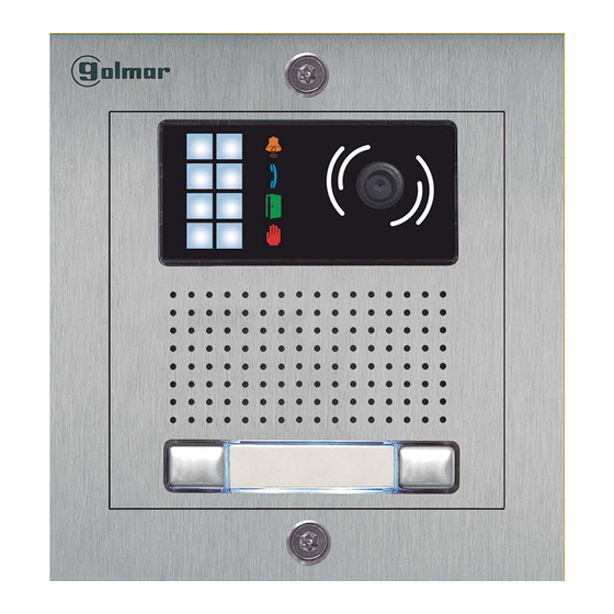
STAINLESS STEEL NEXA MODULAR GB2 VIDEO DOOR ENTRY SYSTEM KIT – HOUSES DESCRIPTION OF THE EL632 GB2A SOUND MODULE Description of the EL632 GB2A sound module: Front. Colour television camera. LEDs (visual signals for people with impaired hearing). LEDs (activation in low light conditions). -
Page 5: Positioning The Embedding Box
STAINLESS STEEL NEXA MODULAR GB2 VIDEO DOOR ENTRY SYSTEM KIT – HOUSES INSTALLATION OF THE DOOR PANEL Positioning the embedding box: 1850 1650 1450 Make a hole in the wall to position the top of the door panel at a height of 1.65m. -
Page 6: Codes Assigned To The Call Buttons
STAINLESS STEEL NEXA MODULAR GB2 VIDEO DOOR ENTRY SYSTEM KIT – HOUSES INSTALLATION OF THE DOOR PANEL Codes assigned to the call buttons of the sound module: EL632 GB2A C1 NA1 C2 AP+ AP- P1 P2 BUSBUS Relay 1 Relay 2... -
Page 7: Description Of The Configuration Jumper
STAINLESS STEEL NEXA MODULAR GB2 VIDEO DOOR ENTRY SYSTEM KIT – HOUSES INSTALLATION OF THE DOOR PANEL Description of the configuration jumper: Important: Do not change the configuration jumper's factory position. Factory setting. Description of the door panel illumination LEDs (for low light conditions): The door panel lighting LEDs will turn on during a call if the door panel lighting at that moment is low. -
Page 8: Setting The Door Panel Communication Volume
STAINLESS STEEL NEXA MODULAR GB2 VIDEO DOOR ENTRY SYSTEM KIT – HOUSES INSTALLATION OF THE DOOR PANEL Setting the door panel communication volume: If the audio volume of the door panel is too low after turning it on, follow these steps: Call the apartment. -
Page 9: Configuring The Contact Type For Relay 1 And Relay 2 (Lock Release)
STAINLESS STEEL NEXA MODULAR GB2 VIDEO DOOR ENTRY SYSTEM KIT – HOUSES INSTALLATION OF THE DOOR PANEL Configuring the contact type for Relay 1 and Relay 2 (lock release): To change the contact type for lock release activation of Relay 1 and Relay 2 of the door panel, follow these steps: Disconnect the door panel's power supply. -
Page 10: Fa-Gb2/A Power Supply Installation
DIN 46277 DIN rail latch release. IMPORTANT the maximum number of units that can be connected to an FA-GB2/A power supply is 18 PENTHA GB2 monitors. Replace the protective cover once the input terminals have been wired. INSTALLATION OF THE LOCK RELEASE... -
Page 11: Wiring Diagrams
Configure the end of line in Lock release the last monitor. max. 12 Vdc/270mA. DIP 6 to ON. ( ) 1 Important: For AC lock releases or a second lock release, see diagram 'Connection of Golmar AC and DC lock releases' on p. 18. - Page 12 DIP 6 to ON. ( ) 1 ( ) 1 Lock release max. 12 Vdc/270mA. ( ) 1 Important: For AC lock releases or a second lock release, see diagram 'Connection of Golmar AC and DC lock releases' on p. 18.
- Page 13 Relay 1 Relay 2 12Vdc the last monitor. DIP 6 to ON. Lock release max. 12 Vdc/270mA. Important: For AC lock releases or a second lock release, see diagram 'Connection of Golmar AC and DC lock releases' on p. 18.
- Page 14 Configure the end of line in 12Vdc the last monitor. DIP 6 to ON. Lock release max. 12 Vdc/270mA. ( ) 2 Important: For AC lock releases or a second lock release, see diagram 'Connection of Golmar AC and DC lock releases' on p. 18.
- Page 15 Configure the end of line in the last monitor. DIP 6 to ON. Lock release max. 12 Vdc/270mA. Important: For AC lock releases or a second lock release, see diagram 'Connection of Golmar AC and DC lock releases' on p. 18.
- Page 16 Configure the end of line in the last monitor. Lock release DIP 6 to ON. max. 12 Vdc/270mA. ( ) 2 Important: For AC lock releases or a second lock release, see diagram 'Connection of Golmar AC and DC lock releases' on p. 18.
- Page 17 Relay 2 Relay 1 Relay 2 12Vdc 12Vdc Lock release Lock release max. 12 Vdc/270mA. max. 12 Vdc/270mA. Important: For AC lock releases or a second lock release, see diagram 'Connection of Golmar AC and DC lock releases' on p. 18.
-
Page 18: Wiring Diagrams
STAINLESS STEEL NEXA MODULAR GB2 VIDEO DOOR ENTRY SYSTEM KIT – HOUSES WIRING DIAGRAMS: Connection of Golmar DC and AC lock releases. Connection of 2 DC lock releases without 'AP': Access panel To the FA-GB2/A power supply C1 NA1 C2 AP+ AP- P1 P2 BUSBUS... -
Page 19: Notes
STAINLESS STEEL NEXA MODULAR GB2 VIDEO DOOR ENTRY SYSTEM KIT – HOUSES NOT S:... - Page 20 C/ Silici, 13 08940- Cornellá de Llobregat SPAIN Golmar se reserva el derecho a cualquier modificación sin previo aviso. Golmar se réserve le droit de toute modification sans préavis. Golmar reserves the right to make any modifications without prior notice.
Need help?
Do you have a question about the GB2 and is the answer not in the manual?
Questions and answers