GE N60 Instruction Manual
Network stability and
synchrophasor measurement system
Hide thumbs
Also See for N60:
- Instruction manual (666 pages) ,
- Communications manual (532 pages) ,
- Instruction manual (644 pages)
Table of Contents
Advertisement
Quick Links
Download this manual
See also:
Instruction Manual
Advertisement
Table of Contents

Related Manuals for GE N60


Summary of Contents for GE N60
- Page 1 Digital Energy Network Stability and Synchrophasor Measurement System 847710A1.CDR Instruction Manual Product version: 7.3x GE publication code: 1601-0125-AB1 (GEK-119625) E83849 LISTED IND.CONT. EQ. 52TL 1601-0125-AB1...
- Page 2 The contents of this manual are the property of GE Multilin Inc. This documentation is furnished on license and may not be reproduced in whole or in part without the permission of GE Multilin. The content of this manual is for informational use only and is subject to change without notice.
-
Page 3: Table Of Contents
Unpack and inspect ..................3-1 Panel cutouts ....................3-2 3.2.1 Rear terminal layout ......................3-4 Wiring ......................... 3-5 3.3.1 Typical wiring ........................... 3-5 3.3.2 Dielectric strength........................3-6 3.3.3 Control power .......................... 3-6 N60 NETWORK STABILITY AND SYNCHROPHASOR MEASUREMENT SYSTEM – INSTRUCTION MANUAL... - Page 4 Faceplate ..........................4-15 4.2.7 LED indicators........................4-16 4.2.8 Custom LED labeling ......................4-19 4.2.9 Breaker control ........................4-25 4.2.10 Change passwords ......................4-26 4.2.11 Invalid password entry...................... 4-27 Logic diagrams ....................4-28 N60 NETWORK STABILITY AND SYNCHROPHASOR MEASUREMENT SYSTEM – INSTRUCTION MANUAL...
- Page 5 5.7.3 Power swing detect......................5-170 5.7.4 Phase current........................5-179 5.7.5 Voltage elements.......................5-180 5.7.6 Supervising elements ......................5-183 5.7.7 Sensitive directional power ..................5-185 Control elements ..................5-188 5.8.1 Overview..........................5-188 5.8.2 Trip bus...........................5-188 5.8.3 Setting groups........................5-190 N60 NETWORK STABILITY AND SYNCHROPHASOR MEASUREMENT SYSTEM – INSTRUCTION MANUAL...
- Page 6 6.2.15 Direct inputs ..........................6-8 6.2.16 Direct devices status ......................6-8 6.2.17 Direct integer inputs......................6-9 6.2.18 Teleprotection channel tests.....................6-9 6.2.19 Remaining connection status ...................6-9 6.2.20 Parallel Redundancy Protocol (PRP) ................6-10 Metering ......................6-11 N60 NETWORK STABILITY AND SYNCHROPHASOR MEASUREMENT SYSTEM – INSTRUCTION MANUAL...
- Page 7 Upgrade software..................... 9-5 Replace module ....................9-6 Battery ....................... 9-7 9.6.1 Replace battery for RH/RL power supply..............9-7 9.6.2 Replace battery for SH/SL power supply ..............9-8 9.6.3 Dispose of battery........................9-9 N60 NETWORK STABILITY AND SYNCHROPHASOR MEASUREMENT SYSTEM – INSTRUCTION MANUAL...
- Page 8 Clear files and data after uninstall .............9-12 A FLEXANALOG A.1 FlexAnalog items .....................A-1 OPERANDS B RADIUS SERVER B.1 RADIUS server configuration .................B-1 CONFIGURATION C MISCELLANEOUS C.1 Warranty ......................C-1 C.2 Revision history ....................C-1 ABBREVIATIONS INDEX viii N60 NETWORK STABILITY AND SYNCHROPHASOR MEASUREMENT SYSTEM – INSTRUCTION MANUAL...
-
Page 9: Introduction
Ensure that the control power applied to the device, the AC current, and voltage input match the ratings specified on the relay nameplate. Do not apply current or voltage in excess of the specified limits. N60 NETWORK STABILITY AND SYNCHROPHASOR MEASUREMENT SYSTEM – INSTRUCTION MANUAL... -
Page 10: For Further Assistance
Worldwide telephone: +1 905 927 7070 Europe/Middle East/Africa telephone: +34 94 485 88 54 North America toll-free: 1 800 547 8629 Fax: +1 905 927 5098 Worldwide e-mail: multilin.tech@ge.com Europe e-mail: multilin.tech.euro@ge.com Website: http://www.gedigitalenergy.com/multilin N60 NETWORK STABILITY AND SYNCHROPHASOR MEASUREMENT SYSTEM – INSTRUCTION MANUAL... -
Page 11: Product Description
Up to 64 on/off signals can be exchanged between any two N60 devices via digital communications. The relays can be configured in rings with up to 16 devices each using direct fiber (C37.94), G.704, and RS422 interfaces. An optional redundant (dual-channel) communication card supports combinations of the three interfaces allowing different physical connections in each channel. - Page 12 Parallel Redundancy Protocol (PRP) of IEC 62439-3 (clause 4, 2012) when purchased as an option. Settings and actual values can be accessed from the front panel or EnerVista software. The N60 uses flash memory technology that allows field upgrading as new features are added. Firmware and software are upgradable.
-
Page 13: Security
EnerVista software. • CyberSentry security — Advanced security available as a software option. When purchased, the options are automatically enabled, and the default Password security and EnerVista security are disabled. N60 NETWORK STABILITY AND SYNCHROPHASOR MEASUREMENT SYSTEM – INSTRUCTION MANUAL... - Page 14 The N60 supports password entry from a local or remote connection. Local access is defined as any access to settings or commands via the faceplate interface. This includes both keypad entry and the through the faceplate RS232 port. Remote access is defined as any access to settings or commands via any rear communications port.
- Page 15 Command Authorizes Default role except for menu writing CyberSentry Security Device Definition Settings |---------- Product Setup |--------------- Security (CyberSentry) |--------------- Supervisory See table notes See table notes |--------------- Display Properties N60 NETWORK STABILITY AND SYNCHROPHASOR MEASUREMENT SYSTEM – INSTRUCTION MANUAL...
- Page 16 |--------------- Direct Integers |---------- Transducer I/O |---------- Testing |---------- Front Panel Labels Designer |---------- Protection Summary Commands |---------- Virtual Inputs |---------- Clear Records |---------- Set Date and Time User Displays Targets N60 NETWORK STABILITY AND SYNCHROPHASOR MEASUREMENT SYSTEM – INSTRUCTION MANUAL...
-
Page 17: Order Codes
The order code is on the product label and indicates the product options applicable. The N60 is available as a 19-inch rack horizontal mount and consists of the following modules: power supply, CPU, CT/VT, contact input and output, transducer input and output, and inter-relay communications. Module options are specified at the time of ordering. -
Page 18: Order Codes With Enhanced Ct/Vt Modules
IEC 60870-5-103 + IEEE 1588 + PRP + CyberSentry Lvl 1 + IEC 61850 + four PMUs IEC 61850 + PMU + 61850-90-5 IEC 61850 + 2 x PMU + 61850-90-5 N60 NETWORK STABILITY AND SYNCHROPHASOR MEASUREMENT SYSTEM – INSTRUCTION MANUAL... - Page 19 820 nm, multimode, LED, 2 Channels 1300 nm, multimode, LED, 2 Channels Channel 1 - RS422; Channel 2 - 1300 nm, multimode, LED G.703, 2 Channels RS422, 2 Channels, 2 Clock Inputs RS422, 2 Channels N60 NETWORK STABILITY AND SYNCHROPHASOR MEASUREMENT SYSTEM – INSTRUCTION MANUAL...
-
Page 20: Order Codes With Process Bus Modules
IEC 60870-5-103 + IEEE 1588 + PRP + CyberSentry Lvl 1 + four PMUs IEC 60870-5-103 + IEEE 1588 + PRP + CyberSentry Lvl 1 + IEC 61850 + four PMUs IEC 61850 + PMU + 61850-90-5 2-10 N60 NETWORK STABILITY AND SYNCHROPHASOR MEASUREMENT SYSTEM – INSTRUCTION MANUAL... -
Page 21: Replacement Modules
Replacement modules can be ordered separately. When ordering a replacement CPU module or faceplate, provide the serial number of your existing unit. Not all replacement modules apply to the N60 relay. The modules specified in the order codes for the N60 are available as replacement modules for the N60. -
Page 22: Specifications
4 RTD inputs, 4 DCmA outputs (only one 5D module is allowed) 4 DCmA inputs, 4 RTD inputs 8 DCmA inputs 2.4 Specifications Specifications are subject to change without notice. 2-12 N60 NETWORK STABILITY AND SYNCHROPHASOR MEASUREMENT SYSTEM – INSTRUCTION MANUAL... -
Page 23: Protection Elements
Pickup level: 20.00 to 65.00 Hz in steps of 0.01 Dropout level: pickup + 0.03 Hz Level accuracy: ±0.001 Hz Time delay: 0 to 65.535 s in steps of 0.001 N60 NETWORK STABILITY AND SYNCHROPHASOR MEASUREMENT SYSTEM – INSTRUCTION MANUAL 2-13... - Page 24 0.10 to 500.00 in steps of 0.01 Impedance accuracy: ±5% Fwd / reverse angle impedances: 40 to 90° in steps of 1 Angle accuracy: ±2° Characteristic limit angles: 40 to 140° in steps of 1 2-14 N60 NETWORK STABILITY AND SYNCHROPHASOR MEASUREMENT SYSTEM – INSTRUCTION MANUAL...
-
Page 25: User-Programmable Elements
Operating signal mode: signed or absolute value Operating mode: level, delta Comparator direction: over, under Pickup Level: –90.000 to 90.000 pu in steps of 0.001 N60 NETWORK STABILITY AND SYNCHROPHASOR MEASUREMENT SYSTEM – INSTRUCTION MANUAL 2-15... - Page 26 < 8 ms at 60 Hz, < 10 ms at 50 Hz Upper / lower limit for input signal: 0.050 to 90 pu in steps of 0.001 Resolution: 8 bits / full-scale Maximum error: ±0.6% of full-scale 2-16 N60 NETWORK STABILITY AND SYNCHROPHASOR MEASUREMENT SYSTEM – INSTRUCTION MANUAL...
-
Page 27: Monitoring
Sampling rate: 15 to 3600000 ms in steps of 1 Trigger: any FlexLogic operand Mode: continuous or triggered Storage capacity: (NN is dependent on memory) N60 NETWORK STABILITY AND SYNCHROPHASOR MEASUREMENT SYSTEM – INSTRUCTION MANUAL 2-17... -
Page 28: Metering
Update rate: 50 ms VAR-HOURS (POSITIVE AND NEGATIVE) Accuracy: ±2.0% of reading ±0 to 1 10 Range: Mvarh Parameters: three-phase only Update rate: 50 ms FREQUENCY Accuracy at 2-18 N60 NETWORK STABILITY AND SYNCHROPHASOR MEASUREMENT SYSTEM – INSTRUCTION MANUAL... -
Page 29: Inputs
0.0 to 16.0 ms in steps of 0.5 Continuous current draw: 4 mA (when energized) Auto-burnish impulse current: 50 to 70 mA Duration of auto-burnish impulse: 25 to 50 ms N60 NETWORK STABILITY AND SYNCHROPHASOR MEASUREMENT SYSTEM – INSTRUCTION MANUAL 2-19... -
Page 30: Power Supply
200 ms duration at maximum load NOTE: Low range is DC only. HIGH RANGE Nominal DC voltage: 125 to 250 V Minimum DC voltage: 88 V Maximum DC voltage: 300 V 2-20 N60 NETWORK STABILITY AND SYNCHROPHASOR MEASUREMENT SYSTEM – INSTRUCTION MANUAL... -
Page 31: Outputs
FORM-A VOLTAGE MONITOR Applicable voltage: approx. 15 to 250 V DC Trickle current: approx. 1 to 2.5 mA FORM-A CURRENT MONITOR Threshold current: approx. 80 to 100 mA N60 NETWORK STABILITY AND SYNCHROPHASOR MEASUREMENT SYSTEM – INSTRUCTION MANUAL 2-21... - Page 32 L/R = 20 ms 0.8 A L/R = 40 ms CONTROL POWER EXTERNAL OUTPUT (FOR DRY CONTACT INPUT) Capacity: 100 mA DC at 48 V DC Isolation: ±300 Vpk 2-22 N60 NETWORK STABILITY AND SYNCHROPHASOR MEASUREMENT SYSTEM – INSTRUCTION MANUAL...
-
Page 33: Communication Protocols
SIMPLE NETWORK TIME PROTOCOL (SNTP) Clock synchronization error: <10 ms (typical) PRECISION TIME PROTOCOL (PTP) PTP IEEE Std 1588 2008 (version 2) Power Profile (PP) per IEEE Standard PC37.238TM2011 Slave-only ordinary clock Peer delay measurement mechanism N60 NETWORK STABILITY AND SYNCHROPHASOR MEASUREMENT SYSTEM – INSTRUCTION MANUAL 2-23... -
Page 34: Inter-Relay Communications
–7.6 dBm 1300 nm LED, Multimode –11 dBm 1300 nm ELED, Single mode –14 dBm 1300 nm Laser, Single mode –14 dBm 1550 nm Laser, Single mode –14 dBm 2-24 N60 NETWORK STABILITY AND SYNCHROPHASOR MEASUREMENT SYSTEM – INSTRUCTION MANUAL... -
Page 35: Environmental
95% (non-condensing) at 55°C (as per IEC60068-2-30 variant 1, 6 days) OTHER Altitude: 2000 m (maximum) Pollution degree: Overvoltage category: Ingress protection: IP20 front, IP10 back N60 NETWORK STABILITY AND SYNCHROPHASOR MEASUREMENT SYSTEM – INSTRUCTION MANUAL 2-25... -
Page 36: Type Tests
Insulation: class 1, Pollution degree: 2, Over voltage cat II 2.4.12 Production tests THERMAL Products go through an environmental test based upon an Accepted Quality Level (AQL) sampling process. 2-26 N60 NETWORK STABILITY AND SYNCHROPHASOR MEASUREMENT SYSTEM – INSTRUCTION MANUAL... -
Page 37: Approvals
Normally, cleaning is not required. When dust has accumulated on the faceplate display, wipe with a dry cloth. To avoid deterioration of electrolytic capacitors, power up units that are stored in a de-energized state once per year, for one hour continuously. N60 NETWORK STABILITY AND SYNCHROPHASOR MEASUREMENT SYSTEM – INSTRUCTION MANUAL 2-27... - Page 38 SPECIFICATIONS CHAPTER 2: PRODUCT DESCRIPTION 2-28 N60 NETWORK STABILITY AND SYNCHROPHASOR MEASUREMENT SYSTEM – INSTRUCTION MANUAL...
-
Page 39: Installation
For any issues, contact GE Digital Energy as outlined in the For Further Assistance section in chapter 1. Check that you have the latest copy of the N60 Instruction Manual and the UR Series Communications Guide, for the applicable firmware version, at http://gedigitalenergy.com/multilin/manuals/index.htm... -
Page 40: Panel Cutouts
This section does not apply to the HardFiber Brick; see its instruction manual. The N60 is available as a 19-inch rack horizontal mount unit with a removable faceplate. The faceplate can be specified as either standard or enhanced at the time of ordering. The enhanced faceplate contains additional user-programmable pushbuttons and LED indicators. - Page 41 Figure 3-2: Horizontal mounting (enhanced panel) 18.370” [466,60 mm] 0.280” [7,11 mm] Typ. x 4 CUT-OUT 4.000” [101,60 mm] 17.750” [450,85 mm] 842808A1.CDR Figure 3-3: Horizontal mounting and dimensions (standard panel) N60 NETWORK STABILITY AND SYNCHROPHASOR MEASUREMENT SYSTEM – INSTRUCTION MANUAL...
-
Page 42: Rear Terminal Layout
(nearest to CPU module), indicated by an arrow marker on the terminal block. The figure shows an example of rear terminal assignments. Figure 3-4: Example of modules in F and H slots N60 NETWORK STABILITY AND SYNCHROPHASOR MEASUREMENT SYSTEM – INSTRUCTION MANUAL... -
Page 43: Wiring
CHAPTER 3: INSTALLATION WIRING 3.3 Wiring 3.3.1 Typical wiring Figure 3-5: Typical wiring diagram (T module shown for CPU) N60 NETWORK STABILITY AND SYNCHROPHASOR MEASUREMENT SYSTEM – INSTRUCTION MANUAL... -
Page 44: Dielectric Strength
The power supply module can be ordered for two possible voltage ranges, and the N60 can be ordered with or without a redundant power supply module option. Each range has a dedicated input connection for proper operation. The ranges are as follows (see the Specifications section of chapter 2 for details): •... -
Page 45: Ct/Vt Modules
CT connections for both ABC and ACB phase rotations are identical, as shown in the Typical Wiring Diagram. The exact placement of a zero-sequence core balance CT to detect ground fault current is shown as follows. Twisted-pair cabling on the zero-sequence CT is recommended. N60 NETWORK STABILITY AND SYNCHROPHASOR MEASUREMENT SYSTEM – INSTRUCTION MANUAL... - Page 46 Voltage inputs 8F, 8G, 8L, and 8M modules (4 CTs and 4 VTs) Current inputs 8H, 8J, 8N, and 8R modules (8 CTs) Voltage inputs 8V modules (8 VTs) 842809A1.CDR N60 NETWORK STABILITY AND SYNCHROPHASOR MEASUREMENT SYSTEM – INSTRUCTION MANUAL...
-
Page 47: Process Bus Modules
The terminal configuration for contact inputs is different for the two applications. The contact inputs are grouped with a common return. The N60 has two versions of grouping: four inputs per common return and two inputs per common return. When a contact input/output module is ordered, four inputs per common is used. - Page 48 Where a tilde “~” symbol appears, substitute the slot position of the module. Where a number sign “#” appears, substitute the contact number. NOTE 3-10 N60 NETWORK STABILITY AND SYNCHROPHASOR MEASUREMENT SYSTEM – INSTRUCTION MANUAL...
- Page 49 2 Inputs Fast Form-C ~7a, ~7c 2 Inputs ~7a, ~7c 2 Inputs ~7a, ~7c 2 Inputs Fast Form-C ~8a, ~8c 2 Inputs ~8a, ~8c 2 Inputs ~8a, ~8c 2 Inputs N60 NETWORK STABILITY AND SYNCHROPHASOR MEASUREMENT SYSTEM – INSTRUCTION MANUAL 3-11...
- Page 50 2 Inputs 2 Outputs Solid-State Solid-State ~6a, ~6c 2 Inputs 2 Outputs Not Used Not Used ~7a, ~7c 2 Inputs 2 Outputs Solid-State Solid-State ~8a, ~8c 2 Inputs Not Used 3-12 N60 NETWORK STABILITY AND SYNCHROPHASOR MEASUREMENT SYSTEM – INSTRUCTION MANUAL...
- Page 51 CHAPTER 3: INSTALLATION WIRING Figure 3-10: Contact input and output module wiring (Sheet 1 of 2) N60 NETWORK STABILITY AND SYNCHROPHASOR MEASUREMENT SYSTEM – INSTRUCTION MANUAL 3-13...
- Page 52 CONTACT IN SURGE CONTACT IN CONTACT IN CONTACT IN COMMON SURGE 842763A2.CDR For proper functionality, observe the polarity shown in the figures for all contact input and output connections. 3-14 N60 NETWORK STABILITY AND SYNCHROPHASOR MEASUREMENT SYSTEM – INSTRUCTION MANUAL...
- Page 53 Afterwards the contact input current is reduced to a steady-state current. The impulse has a five-second delay after a contact input changes state. N60 NETWORK STABILITY AND SYNCHROPHASOR MEASUREMENT SYSTEM – INSTRUCTION MANUAL 3-15...
-
Page 54: Transducer Inputs And Outputs
Transducer input modules can receive input signals from external DCmA output transducers (DCmA In) or resistance temperature detectors (RTDs). Hardware and software are provided to receive signals from these external transducers and convert these signals into a digital format for use as required. 3-16 N60 NETWORK STABILITY AND SYNCHROPHASOR MEASUREMENT SYSTEM – INSTRUCTION MANUAL... - Page 55 (5A, 5C, 5D, 5E, and 5F) and channel arrangements that can be ordered for the relay. Where a tilde “~” symbol appears, substitute the slot position of the module. NOTE Figure 3-15: Transducer input/output module wiring The following figure show how to connect RTDs. N60 NETWORK STABILITY AND SYNCHROPHASOR MEASUREMENT SYSTEM – INSTRUCTION MANUAL 3-17...
-
Page 56: Rs232 Faceplate Port
The baud rate for this port can be set, with a default of 19200 bps. Figure 3-17: RS232 faceplate port connection 3.3.9 CPU communication ports 3.3.9.1 Overview In addition to the faceplate RS232 port, there is a rear RS485 communication port. 3-18 N60 NETWORK STABILITY AND SYNCHROPHASOR MEASUREMENT SYSTEM – INSTRUCTION MANUAL... - Page 57 This common voltage is implied to be a power supply common. Some systems allow the shield (drain wire) to be used as common wire and to connect directly to the N60 COM terminal (#3); others function correctly only if the common wire is connected to the N60 COM terminal, but insulated from the shield.
-
Page 58: Irig-B
IRIG-B is a standard time code format that allows stamping of events to be synchronized among connected devices. The IRIG-B code allows time accuracies of up to 100 ns. Using the IRIG-B input, the N60 operates an internal oscillator with 1 µs resolution and accuracy. -
Page 59: Direct Input And Output Communications
The direct inputs and outputs feature makes use of the type 7 series of communications modules, which allow direct messaging between UR devices. These communications modules are outlined in the table later in this section. N60 NETWORK STABILITY AND SYNCHROPHASOR MEASUREMENT SYSTEM – INSTRUCTION MANUAL 3-21... - Page 60 UR1-Tx1 to UR2-Rx1, UR2-Tx1 to UR3-Rx1, UR3-Tx1 to UR4-Rx1, and UR4-Tx1 to UR1-Rx1 for the first ring; and UR1-Tx2 to UR4-Rx2, UR4-Tx2 to UR3-Rx2, UR3-Tx2 to UR2-Rx2, and UR2-Tx2 to UR1-Rx2 for the second ring. Figure 3-22: Direct input and output dual-channel connection 3-22 N60 NETWORK STABILITY AND SYNCHROPHASOR MEASUREMENT SYSTEM – INSTRUCTION MANUAL...
-
Page 61: Fiber: Led And Eled Transmitters
The following figure shows the configuration for the 7A, 7B, 7C, 7H, 7I, and 7J fiber-only modules. Figure 3-24: LED and ELED fiber modules 3.4.3 Fiber laser transmitters The following figure shows the configuration for the 72, 73, 7D, and 7K fiber-laser modules. N60 NETWORK STABILITY AND SYNCHROPHASOR MEASUREMENT SYSTEM – INSTRUCTION MANUAL 3-23... -
Page 62: Interface
The following figure shows the 64K ITU G.703 co-directional interface configuration. The G.703 module is fixed at 64 kbps. The setting is not SETTINGS PRODUCT SETUP DIRECT I/O DIRECT I/O DATA RATE applicable to this module. 3-24 N60 NETWORK STABILITY AND SYNCHROPHASOR MEASUREMENT SYSTEM – INSTRUCTION MANUAL... - Page 63 Once the clips have cleared the raised edge of the chassis, engage the clips simultaneously. When the clips have locked into position, the module is inserted fully. N60 NETWORK STABILITY AND SYNCHROPHASOR MEASUREMENT SYSTEM – INSTRUCTION MANUAL 3-25...
- Page 64 (S1 = ON) and set timing mode to loop timing (S5 = OFF and S6 = OFF). The switch settings for the internal and loop timing modes are shown. 3-26 N60 NETWORK STABILITY AND SYNCHROPHASOR MEASUREMENT SYSTEM – INSTRUCTION MANUAL...
- Page 65 One source lies on the G.703 line side of the interface while the other lies on the differential Manchester side of the interface. Figure 3-32: G.703 dual loopback mode DMR = Differential Manchester Receiver DMX = Differential Manchester Transmitter G7X = G.703 Transmitter G7R = G.703 Receiver 842775A1.CDR N60 NETWORK STABILITY AND SYNCHROPHASOR MEASUREMENT SYSTEM – INSTRUCTION MANUAL 3-27...
-
Page 66: Rs422 Interface
Terminal timing is a common feature to most synchronous data units that allows the module to accept timing from an external source. Using the 3-28 N60 NETWORK STABILITY AND SYNCHROPHASOR MEASUREMENT SYSTEM – INSTRUCTION MANUAL... - Page 67 831022A3.CDR Data module 1 provides timing to the N60 RS422 interface via the ST(A) and ST(B) outputs. Data module 1 also provides timing to data module 2 TT(A) and TT(B) inputs via the ST(A) and AT(B) outputs. The data module pin numbers have been omitted in the figure because they vary by manufacturer.
-
Page 68: Two-Channel Two-Clock Rs422 Interface
AWG 20-24 twisted shielded pair is recommended for external RS422 connections and ground the shield only at one end. For the direct fiber channel, address power budget issues properly. 3-30 N60 NETWORK STABILITY AND SYNCHROPHASOR MEASUREMENT SYSTEM – INSTRUCTION MANUAL... -
Page 69: Ieee C37.94 Interface
Connection — as per all fiber optic connections, a Tx to Rx connection is required The UR-series C37.94 communication module can be connected directly to any compliant digital multiplexer that supports the IEEE C37.94 standard. The figure shows the concept. N60 NETWORK STABILITY AND SYNCHROPHASOR MEASUREMENT SYSTEM – INSTRUCTION MANUAL 3-31... - Page 70 Once the clips have cleared the raised edge of the chassis, engage the clips simultaneously. When the clips have locked into position, the module is inserted fully. 3-32 N60 NETWORK STABILITY AND SYNCHROPHASOR MEASUREMENT SYSTEM – INSTRUCTION MANUAL...
- Page 71 Modules shipped since January 2012 have status LEDs that indicate the status of the DIP switches, as shown in the following figure. Figure 3-41: Status LEDs The clock configuration LED status is as follows: • Flashing green — loop timing mode while receiving a valid data packet N60 NETWORK STABILITY AND SYNCHROPHASOR MEASUREMENT SYSTEM – INSTRUCTION MANUAL 3-33...
-
Page 72: Activate Relay
NEW SETTING Not Programmed Programmed HAS BEEN STORED When the "NEW SETTING HAS BEEN STORED" message appears, the relay is in "Programmed" state and the "In Service" LED turns on. 3-34 N60 NETWORK STABILITY AND SYNCHROPHASOR MEASUREMENT SYSTEM – INSTRUCTION MANUAL... -
Page 73: Install Software
This device (catalog number F485) connects to the computer using a straight-through serial cable. A shielded twisted-pair (20, 22, or 24 AWG) connects the F485 converter to the N60 rear communications port. The converter terminals (+, –, GND) are connected to the N60 communication module (+, –, COM) terminals. See the CPU Communication Ports section in chapter 3 for details. -
Page 74: System Requirements
Ethernet port of the same type as one of the UR CPU ports or a LAN connection to the UR • Internet access or a DVD drive The following qualified modems have been tested to be compatible with the N60 and the EnerVista software: • US Robotics external 56K FaxModem 5686 •... -
Page 75: Configure The N60 For Software Access
3.7 Configure the N60 for software access You connect remotely to the N60 through the rear RS485 or Ethernet port with a computer running the EnerVista UR Setup software. The N60 also can be accessed locally with a computer through the front panel RS232 port or the rear Ethernet port using the Quick Connect feature. -
Page 76: Configure Serial Communication
3.7.1 Configure serial communication A computer with an RS232 port and a serial cable are required. To use the RS485 port at the back of the relay, a GE Digital Energy F485 converter (or compatible RS232-to-RS485 converter) is required. See the F485 instruction manual for details. -
Page 77: Configure Ethernet Connection
11. Click OK when the relay order code has been received. The new device is added to the Site List window (or Online window) located in the top left corner of the main EnerVista UR Setup window. The Site Device has now been configured for Ethernet communications. Proceed to the Connecting to the N60 section to begin communications. -
Page 78: Automatic Discovery Of Ur Devices
Open the Settings > Product Setup > Display Properties window as shown. The window opens with a status indicator on the lower left of the EnerVista UR Setup window. 3-40 N60 NETWORK STABILITY AND SYNCHROPHASOR MEASUREMENT SYSTEM – INSTRUCTION MANUAL... -
Page 79: Use Quick Connect Via The Front Panel Rs232 Port
Connect a nine-pin to nine-pin RS232 serial cable to the computer and the front panel RS232 port. Verify that the latest version of the EnerVista UR Setup software is installed (available from the GE EnerVista DVD or online from http://www.gedigitalenergy.com/multilin). See the software installation section if not already installed. -
Page 80: Use Quick Connect Via A Rear Ethernet Port
3.8.3 Use Quick Connect via a rear Ethernet port To use the Quick Connect feature to access the N60 from a computer through Ethernet, first assign an IP address to the relay using the front panel keyboard. Press the key until the menu displays. - Page 81 CONNECT TO THE N60 connections window. Right-click the Local Area Connection icon and select Properties. Select the Internet Protocol (TCP/IP) item from the list, and click the Properties button. N60 NETWORK STABILITY AND SYNCHROPHASOR MEASUREMENT SYSTEM – INSTRUCTION MANUAL 3-43...
- Page 82 CHAPTER 3: INSTALLATION Click the “Use the following IP address” box. Enter an IP address with the first three numbers the same as the IP address of the N60 relay and the last number different (in this example, 1.1.1.2). Enter a subnet mask equal to the one set in the N60 (in this example, 255.0.0.0).
- Page 83 If this computer is used to connect to the Internet, re-enable any proxy server settings after the computer has been disconnected from the N60 relay. Start the Internet Explorer software. Select the UR device from the EnerVista Launchpad to start EnerVista UR Setup. N60 NETWORK STABILITY AND SYNCHROPHASOR MEASUREMENT SYSTEM – INSTRUCTION MANUAL 3-45...
- Page 84 Click the Quick Connect button to open the window. Select the Ethernet interface and enter the IP address assigned to the N60, then click the Connect button. The EnerVista UR Setup software creates a site named “Quick Connect” with a corresponding device also named “Quick Connect”...
-
Page 85: Set Up Cybersentry And Change Default Password
If using EnerVista, navigate to Settings > Product Setup > Security. Change the Local Administrator Password, for example. It is strongly recommended that the password for the Administrator be changed from the default. Changing the passwords for the other three roles is optional. N60 NETWORK STABILITY AND SYNCHROPHASOR MEASUREMENT SYSTEM – INSTRUCTION MANUAL 3-47... - Page 86 SET UP CYBERSENTRY AND CHANGE DEFAULT PASSWORD CHAPTER 3: INSTALLATION Figure 3-53: Changing the default password 3-48 N60 NETWORK STABILITY AND SYNCHROPHASOR MEASUREMENT SYSTEM – INSTRUCTION MANUAL...
-
Page 87: Interfaces
The EnerVista UR Setup software is provided with every N60. This chapter outlines the EnerVista software interface features. The EnerVista UR Setup Help File also provides details for getting started and using the software interface. -
Page 88: Event Viewing
IP Address IP Subnet Mask IP Routing When a settings file is loaded to a N60 that is in-service, the following sequence occurs: The N60 takes itself out of service. The N60 issues a UNIT NOT PROGRAMMED major self-test error. -
Page 89: Settings Templates
(settings file templates) and online devices (online settings templates). The functionality is identical for both purposes. Settings files conversion from previous firmware versions is supported. N60 NETWORK STABILITY AND SYNCHROPHASOR MEASUREMENT SYSTEM – INSTRUCTION MANUAL... - Page 90 By default, all settings are specified as locked and displayed against a grey background. The icon on the upper right of the settings window also indicates that the EnerVista software is in EDIT mode. The following example shows the phase time overcurrent settings window in edit mode. N60 NETWORK STABILITY AND SYNCHROPHASOR MEASUREMENT SYSTEM – INSTRUCTION MANUAL...
- Page 91 The following procedure describes how to add password protection to a settings file template. Select a settings file from the offline window on the left of the EnerVista UR Setup window. Select the Template Mode > Password Protect Template option. N60 NETWORK STABILITY AND SYNCHROPHASOR MEASUREMENT SYSTEM – INSTRUCTION MANUAL...
- Page 92 Viewing the settings in template mode also modifies the settings menu, showing only the settings categories that contain editable settings. The effect of applying the template to a typical settings menu is shown as follows. N60 NETWORK STABILITY AND SYNCHROPHASOR MEASUREMENT SYSTEM – INSTRUCTION MANUAL...
- Page 93 Select an installed device or settings file on the left side of the EnerVista UR Setup window. Right-click and select the Template Mode > Remove Settings Template option. Enter the template password and click OK to continue. N60 NETWORK STABILITY AND SYNCHROPHASOR MEASUREMENT SYSTEM – INSTRUCTION MANUAL...
-
Page 94: Secure And Lock Flexlogic Equations
Click the Save button to save and apply changes to the settings template. Select the Template Mode > View In Template Mode option to view the template. Apply a password to the template then click OK to secure the FlexLogic equation. N60 NETWORK STABILITY AND SYNCHROPHASOR MEASUREMENT SYSTEM – INSTRUCTION MANUAL... - Page 95 Right-click the setting file in the offline window area and select the Edit Settings File Properties item. The window opens. N60 NETWORK STABILITY AND SYNCHROPHASOR MEASUREMENT SYSTEM – INSTRUCTION MANUAL...
-
Page 96: Settings File Traceability
When a settings file is transferred to a N60 device, the date, time, and serial number of the N60 are sent back to EnerVista UR Setup and added to the settings file on the local computer. This information can be compared with the N60 actual values at any later date to determine if security has been compromised. - Page 97 With respect to the figure, the traceability feature is used as follows. The transfer date of a settings file written to a N60 is logged in the relay and can be viewed in the EnerVista software or the front panel display. Likewise, the transfer date of a settings file saved to a local computer is logged in the EnerVista software.
-
Page 98: Front Panel Interface
For example, for 127.0.0.1, press 127, then •, then 0, then •, then 0, then •, then 1. To save the address, press key. ENTER The figure shows the sequence to use to enter a setting. Subsequent sections provide more detail. 4-12 N60 NETWORK STABILITY AND SYNCHROPHASOR MEASUREMENT SYSTEM – INSTRUCTION MANUAL... -
Page 99: Menu Navigation
Default values are indicated in this instruction manual in mixed case. In the example shown here, the default access level is Restricted. Highest level Lowest level (setting value) SETTINGS SECURITY ACCESS LEVEL: PRODUCT SETUP Restricted SETTINGS SYSTEM SETUP N60 NETWORK STABILITY AND SYNCHROPHASOR MEASUREMENT SYSTEM – INSTRUCTION MANUAL 4-13... -
Page 100: Changing Settings
VALUE upward from the minimum value. The down arrow decrements the displayed value by the step value, down to VALUE 4-14 N60 NETWORK STABILITY AND SYNCHROPHASOR MEASUREMENT SYSTEM – INSTRUCTION MANUAL... -
Page 101: Faceplate
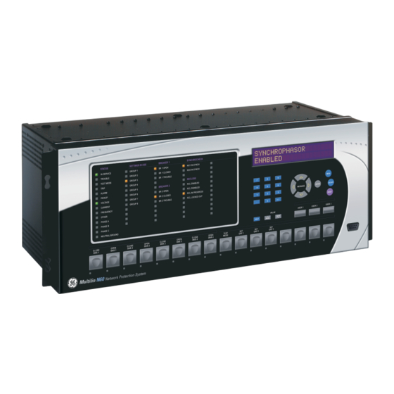
The front panel consists of LED panels, an RS232 port, keypad, LCD display, control pushbuttons, and optional user- programmable pushbuttons. The faceplate is hinged to allow access to the removable modules. N60 NETWORK STABILITY AND SYNCHROPHASOR MEASUREMENT SYSTEM – INSTRUCTION MANUAL 4-15... -
Page 102: Led Indicators
LED indicator or target message, once the condition has been cleared (these RESET latched conditions can also be reset via the menu). SETTINGS INPUT/OUTPUTS RESETTING 4-16 N60 NETWORK STABILITY AND SYNCHROPHASOR MEASUREMENT SYSTEM – INSTRUCTION MANUAL... - Page 103 Support for applying a customized label beside every LED is provided. Default labels are shipped in the label package of every N60, together with custom templates. The default labels can be replaced by user-printed labels. N60 NETWORK STABILITY AND SYNCHROPHASOR MEASUREMENT SYSTEM – INSTRUCTION MANUAL...
- Page 104 FREQUENCY — Indicates frequency was involved • OTHER — Indicates a composite function was involved • PHASE A — Indicates phase A was involved • PHASE B — Indicates phase B was involved 4-18 N60 NETWORK STABILITY AND SYNCHROPHASOR MEASUREMENT SYSTEM – INSTRUCTION MANUAL...
-
Page 105: Custom Led Labeling
LEDs are fully user-programmable. The default labels can be replaced by user-printed labels for both panels as explained in the next section. Figure 4-21: LED panel 2 (default labels) 842785A1.CDR 4.2.8 Custom LED labeling 4.2.8.1 Enhanced faceplate The following procedure requires these pre-requisites: N60 NETWORK STABILITY AND SYNCHROPHASOR MEASUREMENT SYSTEM – INSTRUCTION MANUAL 4-19... - Page 106 NOTE The label package shipped with every N60 contains the three default labels, the custom label template sheet, and the label removal tool. If the default labels are suitable for your application, insert them in the appropriate slots and program the LEDs to match them.
- Page 107 Bend the tab at the center of the tool tail as shown. To remove the LED labels from the N60 enhanced front panel and insert the custom labels: Use the knife to lift the LED label and slide the label tool underneath. Ensure that the bent tabs are pointing away from the relay.
- Page 108 Slide the new LED label inside the pocket until the text is properly aligned with the LEDs, as shown. To remove the user-programmable pushbutton labels from the N60 enhanced front panel and insert the custom labels: Use the knife to lift the pushbutton label and slide the tail of the label tool underneath, as shown. Ensure that the bent 4-22 N60 NETWORK STABILITY AND SYNCHROPHASOR MEASUREMENT SYSTEM –...
- Page 109 Remove the tool and attached user-programmable pushbutton label. Slide the new user-programmable pushbutton label inside the pocket until the text is properly aligned with the N60 NETWORK STABILITY AND SYNCHROPHASOR MEASUREMENT SYSTEM – INSTRUCTION MANUAL 4-23...
- Page 110 ( LED MODULE ) ( BLANK MODULE ) FEEDER MANAGEMENT RELAY 842722A1.CDR Place the left side of the customized module back to the front panel frame, then snap back the right side. 4-24 N60 NETWORK STABILITY AND SYNCHROPHASOR MEASUREMENT SYSTEM – INSTRUCTION MANUAL...
-
Page 111: Breaker Control
Microsoft Word 97 or later software for editing the template • 1 each of: 8.5" x 11" white paper, exacto knife, ruler, custom display module (GE part number: 1516-0069), and a custom module cover (GE part number: 1502-0015) To customize the display: Open the LED panel customization template with Microsoft Word. -
Page 112: Change Passwords
When entering a settings or command password via EnerVista or any serial interface, the user must enter the corresponding connection password. If the connection is to the back of the N60, the remote password must be used. If the connection is to the RS232 port of the faceplate, the local password must be used. -
Page 113: Invalid Password Entry
By default, when an incorrect Command or Setting password has been entered via the faceplate interface three times within five minutes, the FlexLogic operand is set to “On” and the N60 does not allow settings or command LOCAL ACCESS DENIED level access via the faceplate interface for five minutes. -
Page 114: Logic Diagrams
TRIP BUS 1 PKP = Enabled TRIP BUS 1 BLOCK = Off SETTINGS TRIP BUS 1 LATCHING = Enabled TRIP BUS 1 RESET = Off FLEXLOGIC OPERAND RESET OP 842023A1.CDR 4-28 N60 NETWORK STABILITY AND SYNCHROPHASOR MEASUREMENT SYSTEM – INSTRUCTION MANUAL... - Page 115 CHAPTER 4: INTERFACES LOGIC DIAGRAMS N60 NETWORK STABILITY AND SYNCHROPHASOR MEASUREMENT SYSTEM – INSTRUCTION MANUAL 4-29...
- Page 116 LOGIC DIAGRAMS CHAPTER 4: INTERFACES 4-30 N60 NETWORK STABILITY AND SYNCHROPHASOR MEASUREMENT SYSTEM – INSTRUCTION MANUAL...
-
Page 117: Settings
DATA LOGGER See page 5-87 DEMAND See page 5-88 USER-PROGRAMMABLE See page 5-90 LEDS USER-PROGRAMMABLE See page 5-93 SELF TESTS N60 NETWORK STABILITY AND SYNCHROPHASOR MEASUREMENT SYSTEM – INSTRUCTION MANUAL... - Page 118 GROUPED ELEMENTS SETTING GROUP 2 SETTING GROUP 3 SETTING GROUP 4 SETTING GROUP 5 N60 NETWORK STABILITY AND SYNCHROPHASOR MEASUREMENT SYSTEM – INSTRUCTION MANUAL...
- Page 119 DIRECT OUTPUTS See page 5-232 DIRECT ANALOGS See page 5-236 DIRECT INTEGERS See page 5-238 TELEPROTECTION See page 5-240 N60 NETWORK STABILITY AND SYNCHROPHASOR MEASUREMENT SYSTEM – INSTRUCTION MANUAL...
-
Page 120: Overview
For example, if CT1 = 300 / 5 A and CT2 = 100 / 1 A, then in order to sum these, CT2 is scaled to the CT1 ratio. In this case, the base quantity is 300 A primary, 5 A secondary for CT1, and 300/(100/1) = 3 A secondary for CT2. N60 NETWORK STABILITY AND SYNCHROPHASOR MEASUREMENT SYSTEM – INSTRUCTION MANUAL... - Page 121 The DPO event is created when the measure and decide comparator output transits from the pickup state (logic 1) to the dropout state (logic 0). This can happen when the element is in the operate state if the reset delay time is not 0. N60 NETWORK STABILITY AND SYNCHROPHASOR MEASUREMENT SYSTEM – INSTRUCTION MANUAL...
-
Page 122: Introduction To Ac Sources
CT1 and CT2 and can name this source as “Wdg1 I.” Once the sources have been configured, the user has them available as selections for the choice of input signal for the protection elements and as metered quantities. N60 NETWORK STABILITY AND SYNCHROPHASOR MEASUREMENT SYSTEM – INSTRUCTION MANUAL... -
Page 123: Product Setup
Password security — Basic security present by default • EnerVista security — Role-based access to various EnerVista software screens and configuration elements. The feature is present by default in the EnerVista software. N60 NETWORK STABILITY AND SYNCHROPHASOR MEASUREMENT SYSTEM – INSTRUCTION MANUAL... - Page 124 To reset the unit after a lost password: Email GE customer service at multilin.tech@ge.com with the serial number and using a recognizable corporate email account. Customer service provides a code to reset the relay to the factory defaults.
- Page 125 When entering a settings or command password via EnerVista or any serial interface, the user must enter the corresponding connection password. If the connection is to the back of the N60, the remote password must be used. If the connection is to the RS232 port of the faceplate, the local password must be used.
- Page 126 Click the OK button. The password is checked to ensure that it meets requirements. If you establish a local (serial) connection to the relay, you cannot view remote passcodes. NOTE 5-10 N60 NETWORK STABILITY AND SYNCHROPHASOR MEASUREMENT SYSTEM – INSTRUCTION MANUAL...
- Page 127 INVALID ATTEMPTS BEFORE LOCKOUT The N60 provides a means to raise an alarm upon failed password entry. If password verification fails while accessing a password-protected level of the relay (either settings or commands), the FlexLogic operand is asserted.
- Page 128 If access is permitted and an off-to-on transition of the FlexLogic operand is detected, the timeout is restarted. The status of this timer updates every five seconds. 5-12 N60 NETWORK STABILITY AND SYNCHROPHASOR MEASUREMENT SYSTEM – INSTRUCTION MANUAL...
- Page 129 Check the Enable Security check box in the lower-left corner to enable the security management system. If you force password entry by using this feature, ensure that you know the Administrator password. If you do not know the password and are locked out of the software, contact GE Digital Energy for the default password NOTE or a UR device.
- Page 130 The EnerVista security management system must be enabled (the Enable Security check box is enabled) To modify user privileges: Select the Security > User Management item from the top menu to open the user management window. Locate the username in the User field. 5-14 N60 NETWORK STABILITY AND SYNCHROPHASOR MEASUREMENT SYSTEM – INSTRUCTION MANUAL...
- Page 131 Click OK to save the changes. 5.3.1.4 CyberSentry security The EnerVista software provides the means to configure and authenticate the N60 access using either a server or the device. Access to functions depends on user role. The login screen of EnerVista has two options for access to the N60, these being Server and Device authentication.
- Page 132 In this case, it uses built-in roles (Administrator, Engineer, Supervisor, Operator, Observer), as login accounts and the associated passwords are stored on the N60 device. In this case, access is not user-attributable. In cases where user-attributable access is required, especially for auditable processes for compliance reasons, use server authentication (RADIUS) only.
- Page 133 CHAPTER 5: SETTINGS PRODUCT SETUP Figure 5-3: CyberSentry security panel For the Device > Settings > Product Setup > Supervisory option, the panel looks like the following. N60 NETWORK STABILITY AND SYNCHROPHASOR MEASUREMENT SYSTEM – INSTRUCTION MANUAL 5-17...
- Page 134 EAP-TTLS EAP-TTLS Administrator Authentication server. Currently fixed to EAP-TTLS. Method Timeout Timeout in seconds between re- 9999 Administrator transmission requests Retries Number of retries before giving up 9999 Administrator 5-18 N60 NETWORK STABILITY AND SYNCHROPHASOR MEASUREMENT SYSTEM – INSTRUCTION MANUAL...
- Page 135 All RADIUS users are Password following Me1# role and password-protected. Requirements password Administrator, section earlier section for except for in this chapter requireme Supervisor, where it is only itself N60 NETWORK STABILITY AND SYNCHROPHASOR MEASUREMENT SYSTEM – INSTRUCTION MANUAL 5-19...
- Page 136 This role also has the ability to forcefully log off any other role and clear the security event log. This role can also be disabled, but only through a Supervisor authentication. When this role is disabled its permissions are assigned to the Administrator role. 5-20 N60 NETWORK STABILITY AND SYNCHROPHASOR MEASUREMENT SYSTEM – INSTRUCTION MANUAL...
- Page 137 • Observer — This role has read-only access to all N60 settings. This role allows unlimited concurrent access but it has no download access to any files on the device. Observer is the default role if no authentication has been done to the device.
- Page 138 If this setting is disabled, the UR device accepts settings changes and firmware upgrade. This role is disabled by default. 5-22 N60 NETWORK STABILITY AND SYNCHROPHASOR MEASUREMENT SYSTEM – INSTRUCTION MANUAL...
- Page 139 RADIUS server. Once both the RADIUS server and the parameters for connecting the UR to the server have been configured, you can choose Server authentication on the login screen of EnerVista. N60 NETWORK STABILITY AND SYNCHROPHASOR MEASUREMENT SYSTEM – INSTRUCTION MANUAL 5-23...
- Page 140 — 255 chars maximum, but in the security log it is truncated to 20 characters Username — Device IP address IP address — 16 bit unsigned, of type format F617 Role Enumeration Role None Administrator Supervisor Engineer Operator Factory 5-24 N60 NETWORK STABILITY AND SYNCHROPHASOR MEASUREMENT SYSTEM – INSTRUCTION MANUAL...
-
Page 141: Display Properties
— Flash messages are status, warning, error, and information messages displayed in response to FLASH MESSAGE TIME certain key presses during settings programming. These messages override any normal messages. Use this setting to change the duration of flash messages on the display. N60 NETWORK STABILITY AND SYNCHROPHASOR MEASUREMENT SYSTEM – INSTRUCTION MANUAL 5-25... - Page 142 Some customers prefer very low currents to display as zero, while others prefer the current to display even when the value reflects noise rather than the actual signal. The N60 applies a cut-off value to the magnitudes and angles of the measured currents.
-
Page 143: Clear Relay Records
Selected records can be cleared from user-programmable conditions with FlexLogic operands. Assigning user- programmable pushbuttons to clear specific records is a typical application for these commands. Since the N60 responds to rising edges of the configured FlexLogic operands, they must be asserted for at least 50 ms to take effect. - Page 144 5.3.4.3 Ethernet network topology The N60 has three Ethernet ports. Each Ethernet port must belong to a different network or subnetwork. Configure the IP address and subnet to ensure that each port meets this requirement. Two subnets are different when the bitwise AND operation performed between their respective IP address and mask produces a different result.
- Page 145 SCADA is provided through LAN2. P2 and P3 are connected to LAN2, where P2 is the primary channel and P3 is the redundant channel. In this configuration, P3 uses the IP and MAC addresses of P2. N60 NETWORK STABILITY AND SYNCHROPHASOR MEASUREMENT SYSTEM – INSTRUCTION MANUAL 5-29...
- Page 146 LAN3, to which port 3 (P3) is connected. There is no redundancy. Figure 5-7: Multiple LANS, no redundancy Public Network SCADA EnerVista Software LAN1 LAN2 LAN3 ML3000 ML3000 ML3000 IP1/ IP2/ IP3/ MAC2 MAC3 MAC1 859710A2.vsd 5-30 N60 NETWORK STABILITY AND SYNCHROPHASOR MEASUREMENT SYSTEM – INSTRUCTION MANUAL...
- Page 147 2 is performed. The delay in switching back ensures that rebooted switching devices connected to the N60, which signal their ports as active prior to being completely functional, have time to completely initialize themselves and become active. Once port 2 is active again, port 3 returns to standby mode.
- Page 148 Take care when designing the two LANs, so that no single point of failure (such as a common power supply) is encountered, as such scenarios can bring down both LANs simultaneously. 5-32 N60 NETWORK STABILITY AND SYNCHROPHASOR MEASUREMENT SYSTEM – INSTRUCTION MANUAL...
- Page 149 DEFAULT IPv4 ROUTE GATEWAY ADDRESS: Range: standard IPV4 unicast address format 127.0.0.1 IPv4 NETWORK RT1 DESTINATION: Range: standard IPV4 address format ROUTE 1 127.0.0.1 N60 NETWORK STABILITY AND SYNCHROPHASOR MEASUREMENT SYSTEM – INSTRUCTION MANUAL 5-33...
- Page 150 (RtGwy & Prt1Mask) == (Prt1IP & Prt1Mask) || (RtGwy & Prt2Mask) == (Prt2IP & Prt2Mask) || (RtGwy & Prt3Mask) == (Prt3IP & Prt3Mask) where & is the bitwise-AND operator == is the equality operator || is the logical OR operator 5-34 N60 NETWORK STABILITY AND SYNCHROPHASOR MEASUREMENT SYSTEM – INSTRUCTION MANUAL...
- Page 151 PRT2 SUBNET IP MASK = 255.255.255.0 IPV4 DEFAULT ROUTE: GATEWAY ADDRESS = 10.1.1.1 STATIC NETWORK ROUTE 1: RT1 DESTINATION = 10.1.3.0/24; RT1 NET MASK = 255.255.255.0; and RT1 GATEWAY = 10.1.2.1 N60 NETWORK STABILITY AND SYNCHROPHASOR MEASUREMENT SYSTEM – INSTRUCTION MANUAL 5-35...
- Page 152 For more information on the protocol, including the memory map table, see the UR Series Communications Guide. — When using the Modbus protocol on the RS232 port, the N60 responds regardless of the MODBUS SLAVE ADDRESS programmed. For the RS485 port, each device on the serial bus must have a unique slave address MODBUS SLAVE ADDRESS from 1 to 254.
- Page 153 0 disables Modbus over TCP/IP, meaning closes the Modbus TCP port. When the port number is changed to 0, the change takes effect when the N60 is restarted. When it is set to 0, use the front panel or serial port to communicate with the relay.
- Page 154 Range: 1, 2, 5, 6 DEFAULT VARIATION: 1 DNP OBJECT 21 Range: 1, 2, 9, 10 DEFAULT VARIATION: 1 DNP OBJECT 22 Range: 1, 2, 5, 6 DEFAULT VARIATION: 1 5-38 N60 NETWORK STABILITY AND SYNCHROPHASOR MEASUREMENT SYSTEM – INSTRUCTION MANUAL...
- Page 155 DNP ADDRESS unique address to each DNP slave. The N60 can specify a maximum of five clients for its DNP connections. These are IP addresses for the controllers to which the N60 can connect. The settings follow. SETTINGS PRODUCT SETUP COMMUNICATIONS DNP PROTOCOL DNP NETWORK CLIENT ADDRESSES ...
- Page 156 DNP TCP connection for greater than the time specified by this setting, the connection is aborted by the N60. This frees up the connection to be re-used by a client. Any change takes effect after cycling power to the relay.
- Page 157 FlexLogic operand. See the Introduction to FlexLogic section in this chapter for the range of assignable operands. Changes to the DNP / IEC 60870-5-104 point lists take effect when the N60 is restarted. The menu for the analog input points (DNP) or MME points (IEC 60870-5-104) follows.
- Page 158 EnerVista setup for IEC 61850 The EnerVista UR Setup software provides the interface to configure N60 settings for the IEC 61850 protocol. This section describes this interface. The software also supports import and export of IEC 61850 Substation Configuration Language (SCL) files as documented in the UR Series Communications Guide.
- Page 159 Opening the IEC 61850 window while online causes the UR Setup software to retrieve and import an SCL file from the connected N60. This SCD file contains all the settings in the UR at the time of the file request, both those that are mapped into the IEC 61850 information model (that is, the "public"...
- Page 160 When the Save button in the online IEC 61850 window is clicked, UR Setup software prepares a configured IED description (CID) file containing all the device’s settings and sends the CID file to the connected N60. On receipt of a CID file, the N60 checks it for correctness, and if no error is found, reboots using the settings in the CID file.
- Page 161 The value entered sets the value of the data attribute <LDName>/LPHD1.PhyNam.longitude. This data attribute is provided by the protocol to allow the user to declare the geographical position of the device in WGS84 coordinates - longitude. Negative values indicate a western longitude. N60 NETWORK STABILITY AND SYNCHROPHASOR MEASUREMENT SYSTEM – INSTRUCTION MANUAL 5-45...
- Page 162 Default: 0 This data attribute is provided by the protocol to make changes to the settings of the N60 apparent to clients. The Substation Configuration Tool and UR Setup software advance the value of paramRev each time any setting changes.
- Page 163 The entities whose values are published in GOOSE messages are known as members. The members are itemized in an ordered list known as a data set. Each TxGOOSE can use any one of the data sets provided. See the DataSets section later for details. N60 NETWORK STABILITY AND SYNCHROPHASOR MEASUREMENT SYSTEM – INSTRUCTION MANUAL 5-47...
- Page 164 When set to Disabled, no GOOSE messages are published on N60 Ethernet port 1, and any GOOSE messages received on port 1 are ignored. When set to Enabled, all enabled GOOSE messages are published on N60 Ethernet port 1, and any GOOSE messages received on port 1 are listened to.
- Page 165 The standard recommends that the algorithm used by hardware of the receiving device be considered when assigning destination multicast addresses. Subscribers can use this address to discriminate TxGOOSE1 messages from other GOOSE messages. N60 NETWORK STABILITY AND SYNCHROPHASOR MEASUREMENT SYSTEM – INSTRUCTION MANUAL 5-49...
- Page 166 The value entered sets the timeAllowedtoLive value in published TxGOOSE1 messages. The standard requires subscribers to assume a failure has occurred when another TxGOOSE1 message is not received within the published timeAllowedtoLive time. 5-50 N60 NETWORK STABILITY AND SYNCHROPHASOR MEASUREMENT SYSTEM – INSTRUCTION MANUAL...
- Page 167 RxGOOSE assumes that connectivity is lost. FlexLogic operands (for example, RxGOOSE1 On, RxGOOSE1 Off) reflect the status of each RxGOOSE connectivity. RxGOOSE connectivity of an RxGOOSE with non-zero MAC address is also considered lost after the N60 finishes restart until a message is received. When RxGOOSE connectivity is lost, a common RxGOOSE Fail self-test activates.
- Page 168 <GoCBName> is the name of the publishing control block. The N60 translates the ACSI format required for this setting to the MMS format used in GOOSE messages: <LDName>/LLN0$GO$<GoCBName> If the publisher is a UR 7.3x series device, <LDName> is the value of the publisher's Master functional ldName setting if that setting is not empty, otherwise it is the value of the publisher's IED NAME suffixed with "Master".
- Page 169 Navigate to Settings > Product Setup > Communications > IEC 61850 > GOOSE > RxGOOSE > RxGOOSE Boolean Inputs > RxGOOSE Boolean1 to access the settings for the first RxGOOSE Boolean. The settings and functionality for the others are similar. N60 NETWORK STABILITY AND SYNCHROPHASOR MEASUREMENT SYSTEM – INSTRUCTION MANUAL 5-53...
- Page 170 "Latest/Off" freezes the input in case of lost connectivity. If the latest state is unknown, such as after UR power-up but before the first communication, the input defaults to logic 0. When communication resumes, the input becomes fully operational. 5-54 N60 NETWORK STABILITY AND SYNCHROPHASOR MEASUREMENT SYSTEM – INSTRUCTION MANUAL...
- Page 171 This setting allows the user to assign descriptive text to the names of the four RxGOOSE DPS1 FlexLogic operands. The full operand name is the value of this setting appended with "Intermediate," "On," "Off," or "Bad." This descriptive text also appears in the SCL files associated with the N60. RxGOOSE DPS1 RxGOOSE...
- Page 172 This setting allows the user to assign descriptive text to RxGOOSE Analog1. This descriptive text also appears in the SCL files associated with the N60. Unlike RxGOOSE Booleans and RxGOOSE DPS, the RxGOOSE Analog operands have fixed names, for example RxGOOSE Analog1.
- Page 173 Range: 0.000 to 1000000000.000 in steps of 0.001 Default: 1.000 This setting specifies the per-unit base value for other N60 features to use with the RxGOOSE Analog1 operand. A FlexElement for instance subtracts two quantities after converting their values to integers rescaled to a common base, the common base being the largest of the base values of the two quantities.
- Page 174 Control blocks and data sets can be pre-configured by sending the N60 a CID file. See the UR Series Communications Guide for details. EnerVista UR Setup also can be used to select the data set members and to pre-configure the control blocks.
- Page 175 Range: 0 to 4294967295 in steps of 1 Default: 0 The entered value sets the time interval in milliseconds for the buffering of events for inclusion in a single report. N60 NETWORK STABILITY AND SYNCHROPHASOR MEASUREMENT SYSTEM – INSTRUCTION MANUAL 5-59...
- Page 176 The OptFlds setting is bitstring that controls which of the optional fields are included in report messages. The options are as follows: – sequence-number – report-time-stamp – reason-for-inclusion – data-set-name – data-reference 5-60 N60 NETWORK STABILITY AND SYNCHROPHASOR MEASUREMENT SYSTEM – INSTRUCTION MANUAL...
- Page 177 GGIO1 or GGIO4 data attributes, so that operands without factory assigned data attributes can still have their values published. See the GGIO1 and GGIO4 sections later for details. N60 NETWORK STABILITY AND SYNCHROPHASOR MEASUREMENT SYSTEM – INSTRUCTION MANUAL 5-61...
- Page 178 (db in the figure). Changes to this deadbanded value trigger transmissions when included in GOOSE and report data sets. 5-62 N60 NETWORK STABILITY AND SYNCHROPHASOR MEASUREMENT SYSTEM – INSTRUCTION MANUAL...
- Page 179 Navigate to Settings > Communications > IEC 61850 > System Setup > Breakers > Breaker 1 to access the settings that configure the IEC 61850 protocol interface with the first breaker control and status monitoring element. The settings and functionality for the others are similar. N60 NETWORK STABILITY AND SYNCHROPHASOR MEASUREMENT SYSTEM – INSTRUCTION MANUAL 5-63...
- Page 180 SelectWithValue or Operate service with ctlVal true and with Check.Interlock-check true is requested of either BkrCSWI1.Pos or Bkr0XCBR1.Pos and the selected operand is not activated, a Negative Response (-Rsp) is issued with the REASON CODE of Blocked-by-interlocking. 5-64 N60 NETWORK STABILITY AND SYNCHROPHASOR MEASUREMENT SYSTEM – INSTRUCTION MANUAL...
- Page 181 This setting specifies the maximum time between an operate command to breaker 1 via BkrCSWI1.Pos until BkrCSWI1.Pos.stVal enters the commanded state. The command terminates if the commanded state is not reached in the set time. N60 NETWORK STABILITY AND SYNCHROPHASOR MEASUREMENT SYSTEM – INSTRUCTION MANUAL 5-65...
- Page 182 If a SelectWithValue or Operate service with ctlVal false and with Check.Interlock-check true is requested of DiscCSWI1.Pos or Disc0XSWI1.Pos and the selected operand is not activated, a Negative Response (-Rsp) is issued with the REASON CODE of Blocked-by-interlocking. 5-66 N60 NETWORK STABILITY AND SYNCHROPHASOR MEASUREMENT SYSTEM – INSTRUCTION MANUAL...
- Page 183 > System Setup section later. These signals force a disconnect switch trip or close control while the operand selected by setting XSWI1 ST.LOC OPERAND is not active. "sbo" here is select-before-operate. Enhanced security means that the N60 reports to the client the disconnect switch 1 position the end of the command sequence.
- Page 184 UR reboot immediately following the receipt of a valid CID file. This setting is not mapped into the IEC 61850 information model, but sets the value of SettingControl element attribute actSG in SCL files. 5-68 N60 NETWORK STABILITY AND SYNCHROPHASOR MEASUREMENT SYSTEM – INSTRUCTION MANUAL...
- Page 185 This setting selects the control model clients must use to successfully control the command CLEAR FAULT REPORTS. "sbo" here is select-before-operate. Enhanced security means that the N60 reports to the client the breaker 1 position at the end of the command sequence.
- Page 186 Navigate to Settings > Product Setup > Communications > IEC 61850 > GGIO > GGIO1 to access the settings for GGIO1. Figure 5-27: IEC 61850 GGIO1 panel 5-70 N60 NETWORK STABILITY AND SYNCHROPHASOR MEASUREMENT SYSTEM – INSTRUCTION MANUAL...
- Page 187 Selects the control model for Virtual Input 2, and so on. GGIO4 GGIO4 is a UR feature that allows any of up to 32 UR FlexAnalog operands to be user-mapped to an IEC 61850 information model data attribute. N60 NETWORK STABILITY AND SYNCHROPHASOR MEASUREMENT SYSTEM – INSTRUCTION MANUAL 5-71...
- Page 188 <LDName>/GGIO4.AnIn01.instMag.f. This setting is stored as an IEEE 754 / IEC 60559 floating point number. Because of the large range of this setting, not all possible values can be stored. Some values are rounded to the closest possible floating point number. 5-72 N60 NETWORK STABILITY AND SYNCHROPHASOR MEASUREMENT SYSTEM – INSTRUCTION MANUAL...
- Page 189 NUMBER: 80 The N60 contains an embedded web server and can display pages in a web browser. The web pages are organized as a series of menus that can be accessed starting at the N60 “Main Menu.” Web pages are available showing DNP and IEC 60870-5-104 points lists, Modbus registers, event records, fault reports, and so on.
- Page 190 CHAPTER 5: SETTINGS The Trivial File Transfer Protocol (TFTP) can be used to transfer files from the N60 over a network. The N60 operates as a TFTP server. TFTP client software is available from various sources, including Microsoft Windows NT. The dir.txt file obtained from the N60 contains a list and description of all available files (event records, oscillography, and so on).
- Page 191 0.0.0.0 The N60 can specify a maximum of five clients for its IEC 104 connections. These are IP addresses for the controllers to which the N60 can connect. A maximum of two simultaneous connections are supported at any given time.
- Page 192 PTP, or SNTP, its time is overwritten by these three sources, if any of them is active. If the synchronization timeout occurs and none of IRIG-B, PTP, or SNTP is active, the N60 sets the invalid bit in the time stamp of a time-tagged message.
- Page 193 Spontaneous transmission occurs as a response to cyclic Class 2 requests. If the N60 wants to transmit Class 1 data at that time, it demands access for Class 1 data transmission (ACD=1 in the control field of the response).
- Page 194 FlexAnalog operands. The measurands sent are voltage, current, power, power factor, and frequency. If any other FlexAnalog is chosen, the N60 sends 0 instead of its value. Note that the power is transmitted in KW, not W. Measurands are transmitted as ASDU 3 or ASDU 9 (type identification value set to measurands I, respectively measurands II).
- Page 195 Commands are received as General Command (Type Identification 20). The user can configure the action to perform when an ASDU command comes. A list of available mappings is provided on the N60. This includes 64 virtual inputs (see the following table). The ON and OFF for the same ASDU command can be mapped to different virtual inputs.
-
Page 196: Modbus User Map
The UR Series Communications Guide outlines the Modbus memory map. The map is also viewable in a web browser; enter the IP address of the N60 in the web browser and click the option. 5.3.6 Real-time clock 5.3.6.1 Menu... - Page 197 1588 software option at the time of ordering. See the Order Codes section in chapter 2 for details. The N60 supports the Precision Time Protocol (PTP) specified in IEEE Std 1588 2008 using the Power Profile (PP) specified in IEEE Std C37.238 2011. This enables the relay to synchronize to the international time standard over an Ethernet network that implements PP.
- Page 198 VLAN ID serves no function, and so can be left at its default value. Depending on the characteristics of the device to which the relay is linked directly, VLAN ID can have no effect. This setting applies to all of the relay’s PTP capable ports. 5-82 N60 NETWORK STABILITY AND SYNCHROPHASOR MEASUREMENT SYSTEM – INSTRUCTION MANUAL...
- Page 199 The N60 supports the Simple Network Time Protocol specified in RFC-2030. With SNTP, the N60 can obtain clock time over an Ethernet network. The N60 acts as an SNTP client to receive time values from an SNTP/NTP server, usually a dedicated product using a GPS receiver.
-
Page 200: User-Programmable Fault Report
2:00 The N60 maintains two times: local time and Universal Coordinated Time (UTC). Local time can be provided by IRIG-B signals. UTC time is provided by SNTP servers. The real-time clock (RTC) and timestamps reported in historical records and communication protocols can be incorrect if the Local Time settings are not configured properly. -
Page 201: Oscillography
The user programmable record contains the following information: the user-programmed relay name, detailed firmware revision (x.xx, for example) and relay model (N60), the date and time of trigger, the name of pre-fault trigger (a specific FlexLogic operand), the name of fault trigger (a specific FlexLogic operand), the active setting group at pre-fault trigger, the active setting group at fault trigger, pre-fault values of all programmed analog channels (one cycle before pre-fault trigger), and fault values of all programmed analog channels (at the fault trigger). - Page 202 5.3.8.3 Analog channels SETTINGS PRODUCT SETUP OSCILLOGRAPHY ANALOG CHANNELS ANALOG CHANNELS ANALOG CHANNEL 1: Range: Off, any FlexAnalog parameter See Appendix A for list 5-86 N60 NETWORK STABILITY AND SYNCHROPHASOR MEASUREMENT SYSTEM – INSTRUCTION MANUAL...
-
Page 203: Data Logger
The relay automatically partitions the available memory between the channels in use. The following table outlines examples of storage capacities for a system frequency of 60 Hz. N60 NETWORK STABILITY AND SYNCHROPHASOR MEASUREMENT SYSTEM – INSTRUCTION MANUAL 5-87... -
Page 204: Demand
DEMAND CRNT DEMAND METHOD: Range: Thermal Exponential, Block Interval, Rolling Thermal Exponential Demand POWER DEMAND METHOD: Range: Thermal Exponential, Block Interval, Rolling Thermal Exponential Demand 5-88 N60 NETWORK STABILITY AND SYNCHROPHASOR MEASUREMENT SYSTEM – INSTRUCTION MANUAL... - Page 205 Start Demand Interval logic input pulses. Each new value of demand becomes available at the end of each pulse. Assign a FlexLogic operand to the setting to program the input for the new DEMAND TRIGGER demand interval pulses. N60 NETWORK STABILITY AND SYNCHROPHASOR MEASUREMENT SYSTEM – INSTRUCTION MANUAL 5-89...
-
Page 206: User-Programmable Leds
LEDs. This test checks for hardware failures that lead to more than one LED being turned off from a single logic point. This stage can be interrupted at any time. 5-90 N60 NETWORK STABILITY AND SYNCHROPHASOR MEASUREMENT SYSTEM – INSTRUCTION MANUAL... - Page 207 Configure the LED test to recognize user-programmable pushbutton 1 by making the following entries in the SETTINGS menu: PRODUCT SETUP USER-PROGRAMMABLE LEDS LED TEST : “Enabled” LED TEST FUNCTION : “ ” LED TEST CONTROL PUSHBUTTON 1 ON N60 NETWORK STABILITY AND SYNCHROPHASOR MEASUREMENT SYSTEM – INSTRUCTION MANUAL 5-91...
- Page 208 “Latched,” the LED, once lit, remains so until reset by the faceplate button, from a remote device via a RESET communications channel, or from any programmed operand, even if the LED operand state de-asserts. 5-92 N60 NETWORK STABILITY AND SYNCHROPHASOR MEASUREMENT SYSTEM – INSTRUCTION MANUAL...
-
Page 209: User-Programmable Self-Tests
FUNCTION: Disabled All major self-test alarms are reported automatically with their corresponding FlexLogic operands, events, and targets. Most of the minor alarms can be disabled if so wanted. N60 NETWORK STABILITY AND SYNCHROPHASOR MEASUREMENT SYSTEM – INSTRUCTION MANUAL 5-93... -
Page 210: Control Pushbuttons
The location of the control pushbuttons are shown in the following figures. Figure 5-33: Control pushbuttons (enhanced faceplate) Control pushbuttons 842813A1.CDR An additional four control pushbuttons are included on the standard faceplate when the N60 is ordered with the 12 user- programmable pushbutton option. Figure 5-34: Control pushbuttons (standard faceplate) STATUS... -
Page 211: User-Programmable Pushbuttons
PUSHBTN 1 AUTORST Range: 0.2 to 600.0 s in steps of 0.1 DELAY: 1.0 s PUSHBTN 1 REMOTE: Range: FlexLogic operand PUSHBTN 1 LOCAL: Range: FlexLogic operand N60 NETWORK STABILITY AND SYNCHROPHASOR MEASUREMENT SYSTEM – INSTRUCTION MANUAL 5-95... - Page 212 EVENTS: Disabled The N60 is provided with this optional feature, specified as an option at the time of ordering. Using the order code for your device, see the order codes in chapter 2 for details. User-programmable pushbuttons provide an easy and error-free method of entering digital state (on, off) information. The number of available pushbuttons is dependent on the faceplate module ordered with the relay.
- Page 213 — This setting specifies the top 20-character line of the user-programmable message and is intended to PUSHBTN 1 ID TEXT provide ID information of the pushbutton. See the User-definable Displays section for instructions on how to enter alphanumeric characters from the keypad. N60 NETWORK STABILITY AND SYNCHROPHASOR MEASUREMENT SYSTEM – INSTRUCTION MANUAL 5-97...
- Page 214 — If this setting is enabled, each pushbutton state change is logged as an event into the event PUSHBUTTON 1 EVENTS recorder. The figures show the user-programmable pushbutton logic. 5-98 N60 NETWORK STABILITY AND SYNCHROPHASOR MEASUREMENT SYSTEM – INSTRUCTION MANUAL...
- Page 215 2, 842024A2 SETTING Reset Off = 0 SETTING SETTING Autoreset Delay Autoreset Function = Enabled = Disabled SETTING Drop-Out Timer TIMER 200 ms FLEXLOGIC OPERAND PUSHBUTTON 1 ON 842021A3.CDR N60 NETWORK STABILITY AND SYNCHROPHASOR MEASUREMENT SYSTEM – INSTRUCTION MANUAL 5-99...
-
Page 216: Flex State Parameters
16 states are readable in a single Modbus register. The state bits can be configured so that all states of interest are available in a minimum number of Modbus registers. 5-100 N60 NETWORK STABILITY AND SYNCHROPHASOR MEASUREMENT SYSTEM – INSTRUCTION MANUAL... -
Page 217: User-Definable Displays
Range: up to 20 alphanumeric characters DISP 1 ITEM 1 Range: 0 to 65535 in steps of 1 DISP 1 ITEM 5: Range: 0 to 65535 in steps of 1 N60 NETWORK STABILITY AND SYNCHROPHASOR MEASUREMENT SYSTEM – INSTRUCTION MANUAL 5-101... - Page 218 If the parameters for the top line and the bottom line items have the same units, then the unit is displayed on the bottom line only. The units are only displayed on both lines if the units specified both the top and bottom line items are different. 5-102 N60 NETWORK STABILITY AND SYNCHROPHASOR MEASUREMENT SYSTEM – INSTRUCTION MANUAL...
-
Page 219: Direct Inputs And Outputs
(direct device offline). These FlexLogic operands indicate that direct output DIRECT DEVICE 1 OFF DIRECT DEVICE 16 OFF messages from at least one direct device are not being received. N60 NETWORK STABILITY AND SYNCHROPHASOR MEASUREMENT SYSTEM – INSTRUCTION MANUAL 5-103... - Page 220 128 kbps Channel 1 128 kbps Channel 1 64 kbps, 128 kbps Channel 2 64 kbps, 128 kbps Channel 1 64 kbps, 128 kbps Channel 2 64 kbps, 128 kbps 5-104 N60 NETWORK STABILITY AND SYNCHROPHASOR MEASUREMENT SYSTEM – INSTRUCTION MANUAL...
- Page 221 In this application, apply the following settings. For UR-series IED 1: DIRECT OUTPUT DEVICE ID: “1” DIRECT I/O CH1 RING CONFIGURATION: “Yes” DIRECT I/O DATA RATE: “128 kbps” For UR-series IED 2: N60 NETWORK STABILITY AND SYNCHROPHASOR MEASUREMENT SYSTEM – INSTRUCTION MANUAL 5-105...
- Page 222 DIRECT I/O CH1 RING CONFIGURATION: “Yes” DIRECT I/O CH2 RING CONFIGURATION: “Yes” For UR-series IED 4: DIRECT OUTPUT DEVICE ID: “4” DIRECT I/O CH1 RING CONFIGURATION: “Yes” DIRECT I/O CH2 RING CONFIGURATION: “Yes” 5-106 N60 NETWORK STABILITY AND SYNCHROPHASOR MEASUREMENT SYSTEM – INSTRUCTION MANUAL...
- Page 223 IEDs 2 and 3 constitute a second ring). Figure 5-44: Single-channel open loop configuration UR IED 1 UR IED 2 UR IED 3 842714A1.CDR N60 NETWORK STABILITY AND SYNCHROPHASOR MEASUREMENT SYSTEM – INSTRUCTION MANUAL 5-107...
- Page 224 IED 2 to IED 3: 0.2 of power system cycle The two communications configurations can be applied to both permissive and blocking schemes. Take speed, reliability, and cost into account when selecting the required architecture. 5-108 N60 NETWORK STABILITY AND SYNCHROPHASOR MEASUREMENT SYSTEM – INSTRUCTION MANUAL...
- Page 225 EVENTS: Disabled The N60 checks integrity of the incoming direct input and output messages using a 32-bit CRC. The CRC alarm function is available for monitoring the communication medium noise by tracking the rate of messages failing the CRC check. The monitoring function counts all incoming messages, including messages that failed the CRC check.
-
Page 226: Teleprotection
NUMBER OF CHANNELS NUMBER OF TERMINALS set the to “2.” For a two-terminal system, the can set to “1” or “2” (redundant NUMBER OF CHANNELS NUMBER OF CHANNELS channels). 5-110 N60 NETWORK STABILITY AND SYNCHROPHASOR MEASUREMENT SYSTEM – INSTRUCTION MANUAL... -
Page 227: Installation
5.4 Remote resources 5.4.1 Remote resources configuration When the N60 is ordered with a process card module as a part of HardFiber system, an additional Remote Resources menu tree is available in the EnerVista software to allow configuration of the HardFiber system. -
Page 228: System Setup
Bricks. Remote resources settings configure the point-to-point connection between specific fiber optic ports on the N60 process card and specific Brick. The relay is then configured to measure specific currents, voltages and contact inputs from those Bricks, and to control specific outputs. - Page 229 On a 14.4 kV system with a delta connection and a VT primary to secondary turns ratio of 14400:120, the voltage value entered is 120; that is, 14400 / 120. N60 NETWORK STABILITY AND SYNCHROPHASOR MEASUREMENT SYSTEM – INSTRUCTION MANUAL 5-113...
-
Page 230: Power System
“Disabled” only in unusual circumstances; consult the factory for special variable-frequency FREQUENCY TRACKING applications. The frequency tracking feature functions only when the N60 is in the “Programmed” mode. If the N60 is “Not Programmed,” then metering values are available but can exhibit significant errors. NOTE 5.5.3 Signal sources... - Page 231 CT wiring problem. A disturbance detector is provided for each source. The 50DD function responds to the changes in magnitude of the sequence currents. The disturbance detector logic is as follows. N60 NETWORK STABILITY AND SYNCHROPHASOR MEASUREMENT SYSTEM – INSTRUCTION MANUAL 5-115...
- Page 232 The following figure shows the arrangement of sources used to provide the functions required in this application, and the CT/VT inputs that are used to provide the data. 5-116 N60 NETWORK STABILITY AND SYNCHROPHASOR MEASUREMENT SYSTEM – INSTRUCTION MANUAL...
-
Page 233: Breakers
BREAKER 1 OPEN: Range: FlexLogic operand BREAKER 1 BLK OPEN: Range: FlexLogic operand BREAKER 1 CLOSE: Range: FlexLogic operand BREAKER 1 BLK CLOSE: Range: FlexLogic operand N60 NETWORK STABILITY AND SYNCHROPHASOR MEASUREMENT SYSTEM – INSTRUCTION MANUAL 5-117... - Page 234 1. The number of breaker control elements depends on the number of CT/VT modules specified with the N60. The following settings are available for each breaker control element.
- Page 235 MANUAL CLOSE RECAL1 TIME operator has initiated a manual close command to operate a circuit breaker. — Selects an operand indicating that breaker 1 is out-of-service. BREAKER 1 OUT OF SV N60 NETWORK STABILITY AND SYNCHROPHASOR MEASUREMENT SYSTEM – INSTRUCTION MANUAL 5-119...
- Page 236 SYSTEM SETUP CHAPTER 5: SETTINGS Figure 5-49: Dual breaker control logic (Sheet 1 of 2) IEC 61850 functionality is permitted when the N60 is in “Programmed” mode and not in local control mode. NOTE 5-120 N60 NETWORK STABILITY AND SYNCHROPHASOR MEASUREMENT SYSTEM – INSTRUCTION MANUAL...
- Page 237 IEC 61850 trip and close commands shown is one protection pass only. To maintain the close/ open command for a certain time, do so on the contact outputs using the "Seal-in" setting, in the Trip Output element, or in FlexLogic. N60 NETWORK STABILITY AND SYNCHROPHASOR MEASUREMENT SYSTEM – INSTRUCTION MANUAL 5-121...
-
Page 238: Disconnect Switches
The number of available disconnect switches depends on the number of the CT/VT modules ordered with the N60. — This setting enables and disables operation of the disconnect switch element. - Page 239 This allows for non-simultaneous operation of the poles. IEC 61850 functionality is permitted when the N60 is in “Programmed” mode and not in local control mode. NOTE N60 NETWORK STABILITY AND SYNCHROPHASOR MEASUREMENT SYSTEM – INSTRUCTION MANUAL...
- Page 240 SYSTEM SETUP CHAPTER 5: SETTINGS Figure 5-51: Disconnect switch logic 5-124 N60 NETWORK STABILITY AND SYNCHROPHASOR MEASUREMENT SYSTEM – INSTRUCTION MANUAL...
-
Page 241: Phasor Measurement Unit
CONFIGURATION The N60 is provided with an optional Phasor Measurement Unit (PMU) feature. This feature is specified as a software option at the time of ordering. The number of PMUs available also depends on this option. Using the order code for your device, see the order codes in chapter 2 for details. - Page 242 D60, F60, G60, L30, L90, T60 The figure shows an example of an N60 using four Logical Device PMUs (Logical Device 2 through 5) and four aggregators. The control blocks for the aggregators are located in LD1. A 64 character LDName setting is provided.
- Page 243 MxxMMXU1 ClcMth = M-Class (Note Vaux is mapped to Vneut of MMXU) • MxxMSQI1 ClcMth = M-CLASS • NxxMMXU1 ClcMth = M-Class (Note Vaux is mapped to Vneut of MMXU) • NxxMSQI1 ClcMth = M-CLASS N60 NETWORK STABILITY AND SYNCHROPHASOR MEASUREMENT SYSTEM – INSTRUCTION MANUAL 5-127...
- Page 244 From each PMU, the user selects the phasor information of interest that is mapped into the selected aggregator datset(s). For version 7.0 and later, only FCDA data is supported. 5-128 N60 NETWORK STABILITY AND SYNCHROPHASOR MEASUREMENT SYSTEM – INSTRUCTION MANUAL...
- Page 245 5.5.6.6 Configuration example: CFG-2 based configuration (using IEC 61850-90-5) The N60 is expected to send the CFG-2 file (IEEE C37.118 config. file) upon request from the upstream synchrophasor devices (for example, P30) without stopping R-SV multicasting, as shown in the following figure. The primary domain controller (PDC) does not need to use a stop/start data stream command if the UR protocol is set to IEC 61850-90-5 prior to requesting the configuration via CFG-2 (IEEE C37.118 config.
- Page 246 PMU 1 IDCODE: Range: 1 to 65534 in steps of 1 PMU 1 STN: Range: 32-character ASCII string truncated to 16 characters if mapped into C37.118 Default: GE-UR-PMU GE-UR-PMU 5-130 N60 NETWORK STABILITY AND SYNCHROPHASOR MEASUREMENT SYSTEM – INSTRUCTION MANUAL...
- Page 247 See below CONFIGURATION 90-5 PMU 1 See below CONFIGURATION This section contains basic Phasor Measurement Unit (PMU) data, such as functions, source settings, and names. N60 NETWORK STABILITY AND SYNCHROPHASOR MEASUREMENT SYSTEM – INSTRUCTION MANUAL 5-131...
- Page 248 PMU 1 RATE of the device that are assigned to transmit over this aggregator. For a system frequency of 60 Hz (50 Hz), the N60 generates a reporting mismatch message if the selected rate is not set as 10 Hz, 12 Hz, 15 Hz, 20 Hz, 30 Hz, 60 Hz, or 120 Hz (or 10 Hz, 25 Hz, 50 Hz, or 100 Hz when the system frequency is 50 Hz) when entered via the keypad or software;...
- Page 249 (magnitude and angle) coordinates. This setting complies with bit-0 of the FORMAT field of the IEEE C37.118 configuration frame. With 90-5 PMU, the FORMAT and STYLE are Floating-point and Polar respectively, as specified in the IEC 61850- 90-5 technical report. NOTE N60 NETWORK STABILITY AND SYNCHROPHASOR MEASUREMENT SYSTEM – INSTRUCTION MANUAL 5-133...
- Page 250 PMU 1 IG CALIBRATION Range: –5.00 to 5.00° in steps of 0.05 ANGLE: 0.00° PMU 1 IG CALIBRATION Range: 95.0 to 105.0 in steps of 0.1% MAG: 100.0% 5-134 N60 NETWORK STABILITY AND SYNCHROPHASOR MEASUREMENT SYSTEM – INSTRUCTION MANUAL...
- Page 251 When receiving synchrophasor data at multiple locations, with possibly different reference nodes, it can be more beneficial to allow the central locations to perform the compensation of sequence voltages. • This setting applies to PMU data only. The N60 calculates symmetrical voltages independently for protection and control purposes without applying this correction. •...
- Page 252 Range: 20.00 to 70.00 Hz in steps of 0.01 LOW-FREQ: 49.00 Hz PMU 1 FREQ TRIGGER Range: 20.00 to 70.00 Hz in steps of 0.01 HIGH-FREQ: 61.00 Hz 5-136 N60 NETWORK STABILITY AND SYNCHROPHASOR MEASUREMENT SYSTEM – INSTRUCTION MANUAL...
- Page 253 N60 standards. This element requires that the frequency be above the minimum measurable value. If the frequency is below this value, such as when the circuit is de-energized, the trigger drops out.
- Page 254 Range: 0.00 to 600.00 s in steps of 0.01 DPO TIME: 1.00 s PMU 1 CURR TRIG BLK: Range: FlexLogic operand PMU 1 CURR TRIGGER Range: Self-Reset, Latched, Disabled TARGET: Self-Reset 5-138 N60 NETWORK STABILITY AND SYNCHROPHASOR MEASUREMENT SYSTEM – INSTRUCTION MANUAL...
- Page 255 The trigger responds to the single-phase and three-phase power signals of the Phasor Measurement Unit (PMU) source. N60 NETWORK STABILITY AND SYNCHROPHASOR MEASUREMENT SYSTEM – INSTRUCTION MANUAL 5-139...
- Page 256 Range: 0.00 to 600.00 s in steps of 0.01 DPO TIME: 1.00 s PMU 1 df/dt TRG BLK: Range: FlexLogic operand PMU 1 df/dt TRIGGER Range: Self-Reset, Latched, Disabled TARGET: Self-Reset 5-140 N60 NETWORK STABILITY AND SYNCHROPHASOR MEASUREMENT SYSTEM – INSTRUCTION MANUAL...
- Page 257 “Automatic Overwrite,” the last record is erased to facilitate new recording, when triggered. Under the “Protected” selection, the recorder stops creating new records when the entire memory is used up by the old uncleared records. N60 NETWORK STABILITY AND SYNCHROPHASOR MEASUREMENT SYSTEM – INSTRUCTION MANUAL 5-141...
- Page 258 Range: 1 to 65534 CONFIGURATION TCP PORT: 4712 PMU AGGREGATOR 1: Range: 1 to 65534 UDP PORT: 4713 PMU AGGREGATOR 1: Range: Disabled, Enabled PDC CONTROL: Disabled 5-142 N60 NETWORK STABILITY AND SYNCHROPHASOR MEASUREMENT SYSTEM – INSTRUCTION MANUAL...
- Page 259 — This setting selects the UDP port number that is used by this dataset for network reporting. PMU AGGREGATOR 1: UDP PORT Default setting values for IEEE C37.118 and IEC 6150-90-5 are provided. N60 NETWORK STABILITY AND SYNCHROPHASOR MEASUREMENT SYSTEM – INSTRUCTION MANUAL 5-143...
- Page 260 A FlexLogic operand (SvEna) is provided for each Aggregator that reflects the state of the SvEna control where “1”= Enabled and “0”=Disabled. The figure shows the logic for setting the SvEna control bit. 5-144 N60 NETWORK STABILITY AND SYNCHROPHASOR MEASUREMENT SYSTEM – INSTRUCTION MANUAL...
- Page 261 The range is 0 to 2. Shaded settings in the table are not supported in firmware 7.0. NOTE Table 5-19: Security Enumeration Authentication Encryption N60 NETWORK STABILITY AND SYNCHROPHASOR MEASUREMENT SYSTEM – INSTRUCTION MANUAL 5-145...
-
Page 262: Flexlogic
Figure 5-65: UR architecture overview The states of all digital signals used in the N60 are represented by flags (or FlexLogic operands, which are described later in this section). A digital “1” is represented by a set flag. Any external contact change-of-state can be used to block an element from operating, as an input to a control feature in a FlexLogic equation, or to operate a contact output. - Page 263 The number of pulses counted is equal to the set number Lower than Counter 1 LO The number of pulses counted is below the set number Fixed Logic 1 Logic 0 N60 NETWORK STABILITY AND SYNCHROPHASOR MEASUREMENT SYSTEM – INSTRUCTION MANUAL 5-147...
- Page 264 Bit 7 of eight-bit switch 1 asserted (the most significant bit) 8BIT SWITCH 2 to 8BIT SWITCH 6 Same set of operands as shown for 8 BIT SWITCH 1 5-148 N60 NETWORK STABILITY AND SYNCHROPHASOR MEASUREMENT SYSTEM – INSTRUCTION MANUAL...
- Page 265 DIR POWER 1 DPO The directional power element has dropped out DIR POWER 1 OP The directional power element has operated DIR POWER 2 Same set of operands as DIR POWER 1 N60 NETWORK STABILITY AND SYNCHROPHASOR MEASUREMENT SYSTEM – INSTRUCTION MANUAL 5-149...
- Page 266 Phase B of phase instantaneous overcurrent 1 has dropped out PHASE IOC1 DPO C Phase C of phase instantaneous overcurrent 1 has dropped out PHASE IOC2 and higher Same set of operands as shown for PHASE IOC1 5-150 N60 NETWORK STABILITY AND SYNCHROPHASOR MEASUREMENT SYSTEM – INSTRUCTION MANUAL...
- Page 267 POWER SWING OUTGOING An unstable power swing has been detected (outgoing locus) POWER SWING UN/BLOCK Asserted when power swing is detected and de-asserted when a fault during power swing occurs N60 NETWORK STABILITY AND SYNCHROPHASOR MEASUREMENT SYSTEM – INSTRUCTION MANUAL 5-151...
- Page 268 SUMMATOR 2 OP The summator 2 result is greater than the summator 2 pickup SUMMATOR 6 OP The summator 6 result is greater than the summator 6 pickup 5-152 N60 NETWORK STABILITY AND SYNCHROPHASOR MEASUREMENT SYSTEM – INSTRUCTION MANUAL...
- Page 269 Logic = 0. Does nothing and can be used as a delimiter in an equation list; used as ‘Disable’ by other features. Logic = 1. Can be used as a test setting. N60 NETWORK STABILITY AND SYNCHROPHASOR MEASUREMENT SYSTEM – INSTRUCTION MANUAL 5-153...
- Page 270 LED NEUTRAL/GROUND Asserted when the front panel NEUTRAL/GROUND LED is on LED INDICATORS: LED TEST IN PROGRESS An LED test has been initiated and has not finished LED test 5-154 N60 NETWORK STABILITY AND SYNCHROPHASOR MEASUREMENT SYSTEM – INSTRUCTION MANUAL...
- Page 271 ID of virtual inputs, and the ID of virtual outputs. If the user changes the default name or ID of any of these operands, the assigned name appears in the relay list of operands. The default names are shown in the FlexLogic operands table. N60 NETWORK STABILITY AND SYNCHROPHASOR MEASUREMENT SYSTEM – INSTRUCTION MANUAL 5-155...
-
Page 272: Flexlogic Rules
Operators have only one output. The output of an operator must be used to create a virtual output if it is to be used as an input to two or more operators. 5-156 N60 NETWORK STABILITY AND SYNCHROPHASOR MEASUREMENT SYSTEM – INSTRUCTION MANUAL... -
Page 273: Flexlogic Evaluation
(that is, Virtual Output 3). The final output must also be assigned to a virtual output as virtual output 4, which is programmed in the contact output section to operate relay H1 (that is, contact output H1). N60 NETWORK STABILITY AND SYNCHROPHASOR MEASUREMENT SYSTEM – INSTRUCTION MANUAL 5-157... - Page 274 Prepare a logic diagram for virtual output 4, replacing the logic ahead of virtual output 3 with a symbol identified as virtual output 3, shown as follows. Figure 5-69: Logic for virtual output 4 5-158 N60 NETWORK STABILITY AND SYNCHROPHASOR MEASUREMENT SYSTEM – INSTRUCTION MANUAL...
- Page 275 The result of this process is shown in the figure, which is compared to the logic for virtual output 3 diagram as a check. N60 NETWORK STABILITY AND SYNCHROPHASOR MEASUREMENT SYSTEM – INSTRUCTION MANUAL 5-159...
- Page 276 Now check that the selection of parameters produce the required logic by converting the set of parameters into a logic diagram. The result is shown in the figure, which is compared to the logic for virtual output 4 diagram as a check. 5-160 N60 NETWORK STABILITY AND SYNCHROPHASOR MEASUREMENT SYSTEM – INSTRUCTION MANUAL...
- Page 277 Always test the logic after it is loaded into the relay, in the same way as has been used in the past. Testing can be N60 NETWORK STABILITY AND SYNCHROPHASOR MEASUREMENT SYSTEM – INSTRUCTION MANUAL 5-161...
-
Page 278: Flexlogic Equation Editor
Range: Off, any analog actual value parameter FLEXELEMENT 1 INPUT Range: SIGNED, ABSOLUTE MODE: SIGNED FLEXELEMENT 1 COMP Range: LEVEL, DELTA MODE: LEVEL FLEXELEMENT 1 Range: OVER, UNDER DIRECTION: OVER 5-162 N60 NETWORK STABILITY AND SYNCHROPHASOR MEASUREMENT SYSTEM – INSTRUCTION MANUAL... - Page 279 FLEXELEMENT 1 +IN this setting is set to “Off.” For proper operation of the element, at least one input must be selected. Otherwise, the element does not assert its output operands. N60 NETWORK STABILITY AND SYNCHROPHASOR MEASUREMENT SYSTEM – INSTRUCTION MANUAL 5-163...
- Page 280 FlexElement 1 OpSig 842705A1.CDR In conjunction with the setting, the element can be programmed to provide two extra FLEXELEMENT 1 INPUT MODE characteristics, as shown in the following figure. 5-164 N60 NETWORK STABILITY AND SYNCHROPHASOR MEASUREMENT SYSTEM – INSTRUCTION MANUAL...
- Page 281 BASE = 1 µs FREQUENCY = 1 Hz BASE PHASE ANGLE = 360 degrees (see the UR angle referencing convention) BASE POWER FACTOR = 1.00 BASE RTDs BASE = 100°C N60 NETWORK STABILITY AND SYNCHROPHASOR MEASUREMENT SYSTEM – INSTRUCTION MANUAL 5-165...
-
Page 282: Non-Volatile Latches
LATCH 1 TYPE — If asserted, the specified FlexLogic operands 'sets' Latch 1. LATCH 1 SET — If asserted, the specified FlexLogic operand 'resets' Latch 1. LATCH 1 RESET 5-166 N60 NETWORK STABILITY AND SYNCHROPHASOR MEASUREMENT SYSTEM – INSTRUCTION MANUAL... -
Page 283: Flexmath
Range: –2000.000000 to 2000.000000 in steps of 1.000000 0.000001 SUMMATOR 1 SCALE6: Range: –2000.000000 to 2000.000000 in steps of 1.000000 0.000001 SUMMATOR 1 POS1: Range: FlexLogic operand N60 NETWORK STABILITY AND SYNCHROPHASOR MEASUREMENT SYSTEM – INSTRUCTION MANUAL 5-167... - Page 284 FlexAnalog quantity in other SUMMATOR 1 PU BASE SUMMATOR 1 OUTPUT N60 features, such as FlexElements. This value is used to normalize the FlexAnalog quantity (that is, SUMMATOR 1 OUTPUT change it to a per-unit quantity). See the FlexElements section for details on per-unit base values.
-
Page 285: Overview
SETTINGS GROUPED ELEMENTS SETTING GROUP 1(6) SETTING GROUP 1 POWER SWING See below DETECT PHASE CURRENT See page 5-179 N60 NETWORK STABILITY AND SYNCHROPHASOR MEASUREMENT SYSTEM – INSTRUCTION MANUAL 5-169... -
Page 286: Power Swing Detect
POWER SWING MIDDLE Range: 40 to 140° in steps of 1 LIMIT ANGLE: 90° POWER SWING INNER Range: 40 to 140° in steps of 1 LIMIT ANGLE: 60° 5-170 N60 NETWORK STABILITY AND SYNCHROPHASOR MEASUREMENT SYSTEM – INSTRUCTION MANUAL... - Page 287 (using the operand). POWER SWING UN/BLOCK View the operating characteristic and logic figures along with the following discussion to understand the operation of the element. N60 NETWORK STABILITY AND SYNCHROPHASOR MEASUREMENT SYSTEM – INSTRUCTION MANUAL 5-171...
- Page 288 “Mho”, the element applies the right and left blinders as well. If the blinders are not required, set their settings high enough to effectively disable the blinders. Figure 5-78: Power swing detect mho operating characteristics 5-172 N60 NETWORK STABILITY AND SYNCHROPHASOR MEASUREMENT SYSTEM – INSTRUCTION MANUAL...
- Page 289 POWER SWING UN/BLOCK subsequently unblocked when a fault occurs after the power swing blocking condition has been established N60 NETWORK STABILITY AND SYNCHROPHASOR MEASUREMENT SYSTEM – INSTRUCTION MANUAL 5-173...
- Page 290 The angle of this reach impedance is specified by the setting for POWER SWING REV RCA “Mho,” and the setting for “Quad.” POWER SWING FWD RCA 5-174 N60 NETWORK STABILITY AND SYNCHROPHASOR MEASUREMENT SYSTEM – INSTRUCTION MANUAL...
- Page 291 The actual moment of tripping is controlled by the setting. This time delay is provided TRIP MODE for extra security before the out-of-step trip action is executed. N60 NETWORK STABILITY AND SYNCHROPHASOR MEASUREMENT SYSTEM – INSTRUCTION MANUAL 5-175...
- Page 292 The blocking signal resets the output operand but does not stop the out-of-step tripping sequence. POWER SWING TRIP 5-176 N60 NETWORK STABILITY AND SYNCHROPHASOR MEASUREMENT SYSTEM – INSTRUCTION MANUAL...
- Page 293 CHAPTER 5: SETTINGS GROUPED ELEMENTS Figure 5-81: Power swing detect logic (Sheet 1 of 3) N60 NETWORK STABILITY AND SYNCHROPHASOR MEASUREMENT SYSTEM – INSTRUCTION MANUAL 5-177...
- Page 294 GROUPED ELEMENTS CHAPTER 5: SETTINGS Figure 5-82: Power swing detect logic (Sheet 2 of 3) Figure 5-83: Power swing detect logic (Sheet 3 of 3) 5-178 N60 NETWORK STABILITY AND SYNCHROPHASOR MEASUREMENT SYSTEM – INSTRUCTION MANUAL...
-
Page 295: Phase Current
The input current is the fundamental phasor magnitude. For timing curves, see the publication Instantaneous Overcurrent (IOC) Element Response to Saturated Waveforms in UR Series Relays (GET-8400A). Figure 5-84: Phase instantaneous overcurrent 1 logic N60 NETWORK STABILITY AND SYNCHROPHASOR MEASUREMENT SYSTEM – INSTRUCTION MANUAL 5-179... -
Page 296: Voltage Elements
pickup where T = operating time D = undervoltage delay setting (D = 0.00 operates instantaneously) V = secondary voltage applied to the relay = pickup level pickup 5-180 N60 NETWORK STABILITY AND SYNCHROPHASOR MEASUREMENT SYSTEM – INSTRUCTION MANUAL... - Page 297 The minimum voltage setting selects the operating voltage below which the element is blocked (a setting of “0” allows a dead source to be considered a fault condition). N60 NETWORK STABILITY AND SYNCHROPHASOR MEASUREMENT SYSTEM – INSTRUCTION MANUAL 5-181...
- Page 298 The input voltage is the phase-to-phase voltage, either measured directly from delta-connected VTs or as calculated from phase-to-ground (wye) connected VTs. The figure shows specific voltages to be used for each phase. 5-182 N60 NETWORK STABILITY AND SYNCHROPHASOR MEASUREMENT SYSTEM – INSTRUCTION MANUAL...
-
Page 299: Supervising Elements
Range: FlexLogic operand OPEN POLE C AUX CO: Range: FlexLogic operand OPEN POLE PICKUP Range: 0.000 to 65.535 s in steps of 0.001 DELAY: 0.060 s N60 NETWORK STABILITY AND SYNCHROPHASOR MEASUREMENT SYSTEM – INSTRUCTION MANUAL 5-183... - Page 300 It comprises the reset time of the operating elements it used in conjunction with, the breaker opening time, and breaker auxiliary contacts discrepancy with the main contacts. 5-184 N60 NETWORK STABILITY AND SYNCHROPHASOR MEASUREMENT SYSTEM – INSTRUCTION MANUAL...
-
Page 301: Sensitive Directional Power
DIR POWER 1 Range: 0 to 0.95° in steps of 0.05 CALIBRATION: 0.00° DIR POWER 1 STG1 Range: –1.200 to 1.200 pu in steps of 0.001 SMIN: 0.100 pu N60 NETWORK STABILITY AND SYNCHROPHASOR MEASUREMENT SYSTEM – INSTRUCTION MANUAL 5-185... - Page 302 For example, section (a) in the figure shows settings for reverse power, while section (b) shows settings for low forward power applications. 5-186 N60 NETWORK STABILITY AND SYNCHROPHASOR MEASUREMENT SYSTEM – INSTRUCTION MANUAL...
- Page 303 VTs and CTs. The element responds to the sum of the settings. DIR POWER 1 RCA DIR POWER 1 CALIBRATION N60 NETWORK STABILITY AND SYNCHROPHASOR MEASUREMENT SYSTEM – INSTRUCTION MANUAL 5-187...
-
Page 304: Overview
FUNCTION: Disabled TRIP BUS 1 BLOCK: Range: FlexLogic operand TRIP BUS 1 PICKUP Range: 0.00 to 600.00 s in steps of 0.01 DELAY: 0.00 s 5-188 N60 NETWORK STABILITY AND SYNCHROPHASOR MEASUREMENT SYSTEM – INSTRUCTION MANUAL... - Page 305 — These settings select a FlexLogic operand to be assigned as an input to the trip TRIP BUS 1 INPUT 1 TRIP BUS 1 INPUT 16 bus. N60 NETWORK STABILITY AND SYNCHROPHASOR MEASUREMENT SYSTEM – INSTRUCTION MANUAL 5-189...
-
Page 306: Setting Groups
The active setting group can be indicated on the front display of the UR by configuring User- ELEMENTS Programmable LEDs to display the state of the FlexLogic operands. SETTING GROUP ACT 5-190 N60 NETWORK STABILITY AND SYNCHROPHASOR MEASUREMENT SYSTEM – INSTRUCTION MANUAL... -
Page 307: Selector Switch
SETTINGS CONTROL ELEMENTS SELECTOR SWITCH SELECTOR SWITCH 1(2) SELECTOR SWITCH 1 SELECTOR 1 FUNCTION: Range: Disabled, Enabled Disabled SELECTOR 1 FULL Range: 1 to 7 in steps of 1 RANGE: 7 N60 NETWORK STABILITY AND SYNCHROPHASOR MEASUREMENT SYSTEM – INSTRUCTION MANUAL 5-191... - Page 308 SELECTOR SWITCH 1: POS Z CHNG INITIATED target message is displayed, where Z the pre-selected position. The message is displayed for the time specified by the FLASH 5-192 N60 NETWORK STABILITY AND SYNCHROPHASOR MEASUREMENT SYSTEM – INSTRUCTION MANUAL...
- Page 309 If the position restored from memory is out of range, position 0 (no output operand selected) is applied and an alarm is set ( SELECTOR 1 PWR ALARM N60 NETWORK STABILITY AND SYNCHROPHASOR MEASUREMENT SYSTEM – INSTRUCTION MANUAL 5-193...
- Page 310 The selector position pre-selected via the three-bit control input has not been confirmed before the time The following figures illustrate the operation of the selector switch. In these diagrams, “T” represents a time-out setting. 5-194 N60 NETWORK STABILITY AND SYNCHROPHASOR MEASUREMENT SYSTEM – INSTRUCTION MANUAL...
- Page 311 3BIT A1 3BIT A2 POS 1 POS 2 POS 3 POS 4 POS 5 POS 6 POS 7 BIT 0 BIT 1 BIT 2 STP ALARM BIT ALARM ALARM 842737A1.CDR N60 NETWORK STABILITY AND SYNCHROPHASOR MEASUREMENT SYSTEM – INSTRUCTION MANUAL 5-195...
- Page 312 SETTINGS CONTROL ELEMENTS SETTING GROUPS : “Enabled” SETTING GROUPS FUNCTION : “Off” SETTING GROUPS BLK : “SELECTOR 1 POS 2" GROUP 2 ACTIVATE ON : “SELECTOR 1 POS 3" GROUP 3 ACTIVATE ON 5-196 N60 NETWORK STABILITY AND SYNCHROPHASOR MEASUREMENT SYSTEM – INSTRUCTION MANUAL...
- Page 313 3-bit acknowledge SELECTOR 1 BIT ALARM 3-bit position out SELECTOR 1 ALARM SELECTOR 1 PWR ALARM SELECTOR 1 BIT 0 SELECTOR 1 BIT 1 SELECTOR 1 BIT 2 842012A2.CDR N60 NETWORK STABILITY AND SYNCHROPHASOR MEASUREMENT SYSTEM – INSTRUCTION MANUAL 5-197...
-
Page 314: Underfrequency
— Selects the level at which the underfrequency element is to pickup. For example, if the system UNDERFREQ 1 PICKUP frequency is 60 Hz and the load shedding is required at 59.5 Hz, the setting is 59.50 Hz. Figure 5-98: Underfrequency logic 5-198 N60 NETWORK STABILITY AND SYNCHROPHASOR MEASUREMENT SYSTEM – INSTRUCTION MANUAL... -
Page 315: Overfrequency
OVERFREQ 1 SOURCE setting selects the level at which the overfrequency element is to pickup. OVERFREQ 1 PICKUP Figure 5-99: Overfrequency logic N60 NETWORK STABILITY AND SYNCHROPHASOR MEASUREMENT SYSTEM – INSTRUCTION MANUAL 5-199... -
Page 316: Synchrocheck
F. This time is calculated by: ---------------------------- - Eq. 5-12 360 --------------- - F 2 where is phase angle difference in degrees F is frequency difference in Hz 5-200 N60 NETWORK STABILITY AND SYNCHROPHASOR MEASUREMENT SYSTEM – INSTRUCTION MANUAL... - Page 317 Phase Phase VT and Auxiliary Auxiliary VT Phase Auxiliary V auxiliary (as set for source Z) Auxiliary VT Auxiliary VT Auxiliary Auxiliary V auxiliary (as set for selected sources) N60 NETWORK STABILITY AND SYNCHROPHASOR MEASUREMENT SYSTEM – INSTRUCTION MANUAL 5-201...
- Page 318 The relay uses the auxiliary voltage channel only if that channel is programmed as part of the Source and a three-phase set is not. 5-202 N60 NETWORK STABILITY AND SYNCHROPHASOR MEASUREMENT SYSTEM – INSTRUCTION MANUAL...
-
Page 319: Digital Elements
SETTINGS CONTROL ELEMENTS DIGITAL ELEMENTS DIGITAL ELEMENT 1(48) DIGITAL ELEMENT 1 DIGITAL ELEMENT 1 Range: Disabled, Enabled FUNCTION: Disabled DIG ELEM 1 NAME: Range: 16 alphanumeric characters Dig Element 1 N60 NETWORK STABILITY AND SYNCHROPHASOR MEASUREMENT SYSTEM – INSTRUCTION MANUAL 5-203... - Page 320 Cont Op 1 FlexLogic operand is set. Consequently, the state of these operands can be used as indicators of the integrity of the VOff circuits in which form-A contacts are inserted. 5-204 N60 NETWORK STABILITY AND SYNCHROPHASOR MEASUREMENT SYSTEM – INSTRUCTION MANUAL...
- Page 321 Using the contact input settings, this input is given an ID name, for example, “Cont Ip 1," and is set “On” when the breaker is closed. The settings to use digital element 1 to monitor the breaker trip circuit are indicated (EnerVista example shown). N60 NETWORK STABILITY AND SYNCHROPHASOR MEASUREMENT SYSTEM – INSTRUCTION MANUAL 5-205...
-
Page 322: Digital Counters
FUNCTION: Disabled COUNTER 1 NAME: Range: 12 alphanumeric characters Counter 1 COUNTER 1 UNITS: Range: six alphanumeric characters COUNTER 1 PRESET: Range: –2,147,483,648 to +2,147,483,647 5-206 N60 NETWORK STABILITY AND SYNCHROPHASOR MEASUREMENT SYSTEM – INSTRUCTION MANUAL... - Page 323 If control power is interrupted, the accumulated and frozen values are saved into non-volatile memory during the power-down operation. N60 NETWORK STABILITY AND SYNCHROPHASOR MEASUREMENT SYSTEM – INSTRUCTION MANUAL 5-207...
-
Page 324: Monitoring Elements
DETECTION: Disabled NEUTRAL WIRE OPEN 1 Range: 0.000 to 3.000 pu in steps of 0.001 3 HARM PKP: 0.100 pu Every signal source includes a fuse failure scheme. 5-208 N60 NETWORK STABILITY AND SYNCHROPHASOR MEASUREMENT SYSTEM – INSTRUCTION MANUAL... - Page 325 PHASE VT SECONDARY PHASE VT SECONDARY of DELTA VTs. The setting is found under SETTINGS SYSTEM SETUP AC INPUTS VOLTAGE BANK PHASE VT SECONDARY N60 NETWORK STABILITY AND SYNCHROPHASOR MEASUREMENT SYSTEM – INSTRUCTION MANUAL 5-209...
- Page 326 Range: 0 to 1000 min. in steps of 1 TIME CONST: 45 min. THERM PROT 1 MINIM Range: 0 to 1000 min. in steps of 1 RESET TIME: 20 min. 5-210 N60 NETWORK STABILITY AND SYNCHROPHASOR MEASUREMENT SYSTEM – INSTRUCTION MANUAL...
- Page 327 ------------------------ - Eq. 5-15 – where τ = thermal protection trip time constant = a minimum reset time setting N60 NETWORK STABILITY AND SYNCHROPHASOR MEASUREMENT SYSTEM – INSTRUCTION MANUAL 5-211...
- Page 328 IEC255-8 cold curve or hot curve equations op(In) is the reset time calculated at index n as per the reset time equation rst(In) 5-212 N60 NETWORK STABILITY AND SYNCHROPHASOR MEASUREMENT SYSTEM – INSTRUCTION MANUAL...
-
Page 329: Frequency Rate Of Change
SRC 1 FREQ RATE 1 TREND: Range: Increasing, Decreasing, Bi-directional Increasing FREQ RATE 1 PICKUP: Range: 0.10 to 15.00 Hz/sec in steps of 0.01 0.50 Hz/sec N60 NETWORK STABILITY AND SYNCHROPHASOR MEASUREMENT SYSTEM – INSTRUCTION MANUAL 5-213... - Page 330 If the signal source assigned to the frequency rate of change element is only set to auxiliary VT, then the minimum voltage supervision is 3 V. NOTE 5-214 N60 NETWORK STABILITY AND SYNCHROPHASOR MEASUREMENT SYSTEM – INSTRUCTION MANUAL...
-
Page 331: Digitizers
(from –127 to 127) The figure illustrates the output characteristic of the digitizer element. N60 NETWORK STABILITY AND SYNCHROPHASOR MEASUREMENT SYSTEM – INSTRUCTION MANUAL 5-215... - Page 332 (FlexAnalog parameters) such as power, current amplitude, voltage amplitude, power factor, and so on, can be configured as the digitizer source. Refer to Appendix A for a complete list of FlexAnalog parameters available for the N60. — This setting allows setting symmetrical limits for the input signal. The input signal is truncated to an DIGITIZER 1 LIMIT interval from –LIMIT to +LIMIT before the effective digitization.
- Page 333 : “DIGITIZER 1 BIT 0” DNA- 14 OPERAND : “DIGITIZER 1 BIT 4” DNA- 18 OPERAND : “DIGITIZER 1 BIT 1” DNA- 15 OPERAND : “DIGITIZER 1 BIT 5” DNA- 19 OPERAND N60 NETWORK STABILITY AND SYNCHROPHASOR MEASUREMENT SYSTEM – INSTRUCTION MANUAL 5-217...
-
Page 334: 8-Bit Comparators
Range: 0 to 65.353 s in steps of 0.001 DELAY: 0.000 s 8BIT COMP 1 RESET Range: 0 to 65.353 s in steps of 0.001 DELAY: 0.000 s 5-218 N60 NETWORK STABILITY AND SYNCHROPHASOR MEASUREMENT SYSTEM – INSTRUCTION MANUAL... - Page 335 — This setting specifies if the element operates if the effective operating signal is above (“Over”) or 8BIT COMP 1 DIRECTION below (“Under”) the threshold as illustrated in the following figure. N60 NETWORK STABILITY AND SYNCHROPHASOR MEASUREMENT SYSTEM – INSTRUCTION MANUAL 5-219...
- Page 336 The VT fuse fail at the remote location, or the indication can be used to REMOTE DEVICE OFFLINE block this element. 5-220 N60 NETWORK STABILITY AND SYNCHROPHASOR MEASUREMENT SYSTEM – INSTRUCTION MANUAL...
- Page 337 The application requires the following features. For UR-1: Digitizer to prepare the measured power for sending to the UR-2 IED, and direct outputs to send the digitized power to the UR-2 IED For UR-2: N60 NETWORK STABILITY AND SYNCHROPHASOR MEASUREMENT SYSTEM – INSTRUCTION MANUAL 5-221...
- Page 338 DIRECT INPUT 14 DEVICE ID : “5” DIRECT INPUT 14 BIT NUMBER : “1” DIRECT INPUT 15 DEVICE ID : “6” DIRECT INPUT 15 BIT NUMBER : “1” DIRECT INPUT 16 DEVICE ID 5-222 N60 NETWORK STABILITY AND SYNCHROPHASOR MEASUREMENT SYSTEM – INSTRUCTION MANUAL...
- Page 339 DISP 1 BOTTOM LINE : “8100” (Modbus register address of DISP 1 ITEM 1 8BIT COMP 1 A : “8104” (Modbus register address of DISP 1 ITEM 2 8BIT COMP 1 Out N60 NETWORK STABILITY AND SYNCHROPHASOR MEASUREMENT SYSTEM – INSTRUCTION MANUAL 5-223...
-
Page 340: 8-Bit Switches
8BIT SW 1 ARG A0 to 8BIT SW 1 ARG A7 switch. These operands are routed to the output operands if the control input is in the "Off" position. 5-224 N60 NETWORK STABILITY AND SYNCHROPHASOR MEASUREMENT SYSTEM – INSTRUCTION MANUAL... -
Page 341: Inputs/Outputs
8BIT SW 1 CONTROL: Off = 0 842017A1.CDR 5.9 Inputs/outputs 5.9.1 Contact inputs SETTINGS INPUTS/OUTPUTS CONTACT INPUTS CONTACT INPUTS CONTACT INPUT H5a N60 NETWORK STABILITY AND SYNCHROPHASOR MEASUREMENT SYSTEM – INSTRUCTION MANUAL 5-225... - Page 342 The DC input voltage is compared to a user-settable threshold. A new contact input state must be maintained for a user-settable debounce time in order for the N60 to validate the new contact state. In the following figure, the debounce time is set at 2.5 ms;...
-
Page 343: Virtual Inputs
Range: Disabled, Enabled FUNCTION: Disabled VIRTUAL INPUT 1 ID: Range: up to 12 alphanumeric characters Virt Ip 1 VIRTUAL INPUT 1 Range: Self-Reset, Latched TYPE: Latched N60 NETWORK STABILITY AND SYNCHROPHASOR MEASUREMENT SYSTEM – INSTRUCTION MANUAL 5-227... -
Page 344: Contact Outputs
(virtual output, element state, contact input, or virtual input). An additional FlexLogic operand can be used to SEAL-IN relay. Any change of state of a contact output can be logged as an Event if programmed to do so. 5-228 N60 NETWORK STABILITY AND SYNCHROPHASOR MEASUREMENT SYSTEM – INSTRUCTION MANUAL... - Page 345 Disabled The N60 latching output contacts are mechanically bi-stable and controlled by two separate (open and close) coils. As such they retain their position even if the relay is not powered up. The relay recognizes all latching output contact cards and populates the setting menu accordingly.
- Page 346 Program the Latching Outputs by making the following changes in the SETTINGS INPUTS/OUTPUTS CONTACT menus (assuming an H4L module): OUTPUTS CONTACT OUTPUT H1a CONTACT OUTPUT H1c 5-230 N60 NETWORK STABILITY AND SYNCHROPHASOR MEASUREMENT SYSTEM – INSTRUCTION MANUAL...
-
Page 347: Virtual Outputs
(not including FlexLogic latches) to the reset state. RESET command can be sent from the faceplate button, a remote device via a communications channel, or any RESET RESET programmed operand. N60 NETWORK STABILITY AND SYNCHROPHASOR MEASUREMENT SYSTEM – INSTRUCTION MANUAL 5-231... -
Page 348: Direct Inputs And Outputs
— This setting allows the user to assign a descriptive name to the direct output. DIRECT OUT 1 NAME — This sets the FlexLogic operand that determines the state of this direct output. DIR OUT 1 OPERAND 5-232 N60 NETWORK STABILITY AND SYNCHROPHASOR MEASUREMENT SYSTEM – INSTRUCTION MANUAL... -
Page 349: Application Examples
The following settings are applied (assume Bit 3 is used by all 3 devices to send the blocking signal and Direct Inputs 7, 8, and 9 are used by the receiving device to monitor the three blocking signals). UR IED 2: N60 NETWORK STABILITY AND SYNCHROPHASOR MEASUREMENT SYSTEM – INSTRUCTION MANUAL 5-233... - Page 350 Assume the Hybrid Permissive Overreaching Transfer Trip (Hybrid POTT) scheme is applied using the architecture shown as follows. The scheme output operand is used to key the permission. HYB POTT TX1 5-234 N60 NETWORK STABILITY AND SYNCHROPHASOR MEASUREMENT SYSTEM – INSTRUCTION MANUAL...
- Page 351 5" (forward a message from 1 to 3) DIRECT OUT 3 OPERAND "DIRECT INPUT 6" (forward a message from 3 to 1) DIRECT OUT 4 OPERAND The figure shows the signal flow among the three IEDs. N60 NETWORK STABILITY AND SYNCHROPHASOR MEASUREMENT SYSTEM – INSTRUCTION MANUAL 5-235...
-
Page 352: Direct Analog Inputs And Outputs
0.000 ANALOG 1 TRIGGER: Range: FlexLogic operand The direct analog outputs share the direct input and output settings for device ID, data rate, ring configuration, and channel crossover. 5-236 N60 NETWORK STABILITY AND SYNCHROPHASOR MEASUREMENT SYSTEM – INSTRUCTION MANUAL... - Page 353 DIRECT ANALOG INPUT 1 ACTUAL FlexAnalog value in other N60 features, such as FlexElements. This value is used to normalize the direct analog input 1 FlexAnalog quantity to its per-unit base. See the FlexElements section for additional details on per-unit base values.
-
Page 354: Direct Integer Inputs And Outputs
The communication channel is the same as that used for the direct inputs and outputs. When the direct inputs and outputs, direct analogs, and direct integers features are used together on the same channel, all UR-series relays must be using firmware version 5.70 or higher. 5-238 N60 NETWORK STABILITY AND SYNCHROPHASOR MEASUREMENT SYSTEM – INSTRUCTION MANUAL... - Page 355 “Last Known,” the value of direct integer input 1 remains at the last received value. This value is stored as an unsigned 32-bit integer. N60 NETWORK STABILITY AND SYNCHROPHASOR MEASUREMENT SYSTEM – INSTRUCTION MANUAL 5-239...
-
Page 356: Teleprotection
(teleprotection outputs at the sending end or corresponding teleprotection inputs at the receiving end). On three-terminal two-channel systems, redundancy is achieved by programming signal re-transmittal in the case of channel failure between any pair of relays. 5-240 N60 NETWORK STABILITY AND SYNCHROPHASOR MEASUREMENT SYSTEM – INSTRUCTION MANUAL... -
Page 357: Transducer Inputs/Outputs
DC voltage or temperature. The relay simplifies this process by internally scaling the output from the external transducer and displaying the actual primary parameter. N60 NETWORK STABILITY AND SYNCHROPHASOR MEASUREMENT SYSTEM – INSTRUCTION MANUAL 5-241... -
Page 358: Rtd Inputs
1.5 pu. FlexElement operands are available to FlexLogic for further interlocking or to operate an output contact directly. See the following table for reference temperature values for each RTD type. 5-242 N60 NETWORK STABILITY AND SYNCHROPHASOR MEASUREMENT SYSTEM – INSTRUCTION MANUAL... -
Page 359: Dcma Outputs
Range: –90.000 to 90.000 pu in steps of 0.001 MIN VAL: 0.000 pu DCMA OUTPUT F1 Range: –90.000 to 90.000 pu in steps of 0.001 MAX VAL: 1.000 pu N60 NETWORK STABILITY AND SYNCHROPHASOR MEASUREMENT SYSTEM – INSTRUCTION MANUAL 5-243... - Page 360 The setting is entered in per-unit values. The base units are defined in the same manner as the FlexElement base units. 5-244 N60 NETWORK STABILITY AND SYNCHROPHASOR MEASUREMENT SYSTEM – INSTRUCTION MANUAL...
- Page 361 The minimum and maximum power values to be monitored (in pu) are: 0 kA 6.3 kA minimum current --------- - 0 pu, maximum current ------------- - 1.26 pu Eq. 5-33 5 kA 5 kA N60 NETWORK STABILITY AND SYNCHROPHASOR MEASUREMENT SYSTEM – INSTRUCTION MANUAL 5-245...
-
Page 362: Testing
0.005 230.94 kV + 1.27 kV = 2.42 kV. 5.11 Testing 5.11.1 Test mode function SETTINGS TESTING TEST MODE FUNCTION TESTING TEST MODE Range: Disabled, Isolated, Forcible FUNCTION: Disabled 5-246 N60 NETWORK STABILITY AND SYNCHROPHASOR MEASUREMENT SYSTEM – INSTRUCTION MANUAL... -
Page 363: Test Mode Forcing
CHAPTER 5: SETTINGS TESTING The N60 provides a test facility to verify the functionality of contact inputs and outputs, some communication channels and the phasor measurement unit (where applicable), using simulated conditions. The test mode can be in any of three states: Disabled, Isolated, or Forcible. -
Page 364: Force Contact Inputs
If set to “Freeze,” the output retains its position at the instant before the was Forcible and the TEST MODE FUNCTION operand selected by the setting was On, regardless of later changes in the status of the operand TEST MODE FORCING 5-248 N60 NETWORK STABILITY AND SYNCHROPHASOR MEASUREMENT SYSTEM – INSTRUCTION MANUAL... -
Page 365: Phasor Measurement Unit Test Values
Range: 20.000 to 60.000 Hz in steps of 0.001 FREQUENCY: 60.000 Hz PMU 1 TEST Range: –10.000 to 10.000 Hz/s in steps of 0.001 df/dt: 0.000 Hz/s N60 NETWORK STABILITY AND SYNCHROPHASOR MEASUREMENT SYSTEM – INSTRUCTION MANUAL 5-249... - Page 366 In test mode, the following actions take place: • The Data Invalid / Test Mode bit (bit 15 in the STAT word) is set • The Sim bit in all output datasets is set 5-250 N60 NETWORK STABILITY AND SYNCHROPHASOR MEASUREMENT SYSTEM – INSTRUCTION MANUAL...
-
Page 367: Actual Values
See page 6-6 STATISTICS DIGITAL COUNTERS See page 6-6 SELECTOR SWITCHES See page 6-6 FLEX STATES See page 6-7 N60 NETWORK STABILITY AND SYNCHROPHASOR MEASUREMENT SYSTEM – INSTRUCTION MANUAL... - Page 368 See page 6-21 DIRECT ANALOGS See page 6-21 RxGOOSE Analogs See page 6-21 PHASOR MEASUREMENT See page 6-22 UNIT N60 NETWORK STABILITY AND SYNCHROPHASOR MEASUREMENT SYSTEM – INSTRUCTION MANUAL...
-
Page 369: Status
6.2.2 Virtual inputs ACTUAL VALUES STATUS VIRTUAL INPUTS VIRTUAL INPUTS Virt Ip 1 Range: On, Off Virt Ip 64 Range: On, Off N60 NETWORK STABILITY AND SYNCHROPHASOR MEASUREMENT SYSTEM – INSTRUCTION MANUAL... -
Page 370: Rxgoose Boolean Inputs
Range: On, Off The N60 is provided with optional IEC 61850 capability. This feature is specified as a software option at the time of ordering. See the Order Codes section of chapter 2 for details. 6.2.4 RxGOOSE DPS inputs ACTUAL VALUES ... -
Page 371: Contact Outputs
Range: On, Off The N60 is provided with optional IEC 61850 capability. This feature is specified as a software option at the time of ordering. See the Order Codes section of chapter 2 for details. actual value does not consider RxGOOSE that are not configured or are not used by any RxGOOSE All RxGOOSE Online Input. -
Page 372: Rxgoose Statistics
sqNum: The N60 is provided with optional IEC 61850 capability. This feature is specified as a software option at the time of ordering. See the Order Codes section of chapter 2 for details. — State number. The most recently received value in GOOSE message field stNum. The publisher increments stNum stNum each time that the state of one or more of the GOOSE message members is sent with a revised value. -
Page 373: Flex States
The value 999,999,999 indicates that the magnitude of the estimated error is one second or more, or that the error cannot be estimated. is the present state of the port’s PTP clock. The PTP clock state is: Port 1…3 PTP State N60 NETWORK STABILITY AND SYNCHROPHASOR MEASUREMENT SYSTEM – INSTRUCTION MANUAL... -
Page 374: Direct Inputs
Range: Offline, Online STATUS STATUS: Offline DIRECT DEVICE 16 Range: Offline, Online STATUS: Offline These actual values represent the state of direct devices 1 through 16. N60 NETWORK STABILITY AND SYNCHROPHASOR MEASUREMENT SYSTEM – INSTRUCTION MANUAL... -
Page 375: Direct Integer Inputs
MODBUS TCP (max 4) Range: 0 to 4 DNP TCP(max 2) Range: 0 to 2 IEC-104 TCP(max 2) Range: 0 to 2 PMU TCP Range: 1 to 4 N60 NETWORK STABILITY AND SYNCHROPHASOR MEASUREMENT SYSTEM – INSTRUCTION MANUAL... -
Page 376: Parallel Redundancy Protocol (Prp)
— The maximum number of PMU TCP connections matches the number of aggregators. The maximum number of PMU TCP aggregators for the N60 is 4. The maximum number for the C60 is 2. The maximum number is 1 for other products with a PMU. The remaining number of aggregators displays here. -
Page 377: Metering
CHAPTER 6: ACTUAL VALUES METERING 6.3 Metering 6.3.1 Metering conventions 6.3.1.1 UR convention for measuring power and energy The figure illustrates the conventions established for use in UR devices. N60 NETWORK STABILITY AND SYNCHROPHASOR MEASUREMENT SYSTEM – INSTRUCTION MANUAL 6-11... - Page 378 All phasors calculated by URs and used for protection, control and metering functions are rotating phasors that maintain the correct phase angle relationships with each other at all times. 6-12 N60 NETWORK STABILITY AND SYNCHROPHASOR MEASUREMENT SYSTEM – INSTRUCTION MANUAL...
- Page 379 -- V -- V -- V -- V -- V -- V The above equations apply to currents as well. N60 NETWORK STABILITY AND SYNCHROPHASOR MEASUREMENT SYSTEM – INSTRUCTION MANUAL 6-13...
- Page 380 SYSTEM SETUP POWER SYSTEM FREQUENCY AND PHASE REFERENCE The example above is illustrated in the following figure. Figure 6-3: Measurement convention for symmetrical components SYSTEM VOLTAGES SYMMETRICAL COMPONENTS WYE VTs DE TA VTs 827844A1.CDR 6-14 N60 NETWORK STABILITY AND SYNCHROPHASOR MEASUREMENT SYSTEM – INSTRUCTION MANUAL...
-
Page 381: Sources
0.000 A 0.0° SRC 1 PHASOR Ic: 0.000 A 0.0° SRC 1 PHASOR In: 0.000 A 0.0° SRC 1 ZERO SEQ I0: 0.000 A 0.0° N60 NETWORK STABILITY AND SYNCHROPHASOR MEASUREMENT SYSTEM – INSTRUCTION MANUAL 6-15... - Page 382 0.000 V 0.0° SRC 1 PHASOR Vbc: 0.000 V 0.0° SRC 1 PHASOR Vca: 0.000 V 0.0° SRC 1 ZERO SEQ V0: 0.000 V 0.0° 6-16 N60 NETWORK STABILITY AND SYNCHROPHASOR MEASUREMENT SYSTEM – INSTRUCTION MANUAL...
- Page 383 SRC 1 APPARENT PWR b: 0.000 VA SRC 1 APPARENT PWR c: 0.000 VA SRC 1 POWER FACTOR 3: 1.000 SRC 1 POWER FACTOR a: 1.000 N60 NETWORK STABILITY AND SYNCHROPHASOR MEASUREMENT SYSTEM – INSTRUCTION MANUAL 6-17...
- Page 384 SRC 1 DMD IC MAX: 0.000 A SRC 1 DMD IC DATE: 2001/07/31 16:30:07 SRC 1 DMD W: 0.000 W SRC 1 DMD W MAX: 0.000 W 6-18 N60 NETWORK STABILITY AND SYNCHROPHASOR MEASUREMENT SYSTEM – INSTRUCTION MANUAL...
-
Page 385: Sensitive Directional Power
The effective operating quantities of the sensitive directional power elements display here. The display is useful to calibrate the feature by compensating the angular errors of the CTs and VTs with the use of the settings. CALIBRATION N60 NETWORK STABILITY AND SYNCHROPHASOR MEASUREMENT SYSTEM – INSTRUCTION MANUAL 6-19... -
Page 386: Synchrocheck
= maximum nominal primary RMS value of the +IN and –IN inputs BASE SYNCHROCHECK = maximum primary RMS value of all the sources related to the +IN and –IN inputs BASE (Max Delta Volts) 6-20 N60 NETWORK STABILITY AND SYNCHROPHASOR MEASUREMENT SYSTEM – INSTRUCTION MANUAL... -
Page 387: Digitizers
DIRECT ANALOG 1 UNITS DIRECT ANALOG 32 UNITS 6.3.11 RxGOOSE analogs ACTUAL VALUES METERING RxGOOSE Analogs RxGOOSE RxGOOSE Analog 1 Analogs 0.000 N60 NETWORK STABILITY AND SYNCHROPHASOR MEASUREMENT SYSTEM – INSTRUCTION MANUAL 6-21... -
Page 388: Phasor Measurement Unit
0.000 The N60 is provided with optional GOOSE communications capability. This feature is specified as a software option at the time of ordering. See the Order Codes section of chapter 2 for details. The RxGOOSE Analog values display in this menu. The RxGOOSE Analog values are received via IEC 61850 GOOSE messages sent from other devices. -
Page 389: Pmu Aggregator
5 for information on this feature. 6.4.2 Event records ACTUAL VALUES RECORDS EVENT RECORDS EVENT RECORDS EVENT: XXXX RESET OP(PUSHBUTTON) Date and time stamps N60 NETWORK STABILITY AND SYNCHROPHASOR MEASUREMENT SYSTEM – INSTRUCTION MANUAL 6-23... -
Page 390: Oscillography
COMMANDS CLEAR RECORDS 6.4.5 Phasor Measurement Unit records ACTUAL VALUES RECORDS PMU RECORDS PMU NUMBER OF TRIGGERS: Range: 0 to 65535 in steps of 1 RECORDS 6-24 N60 NETWORK STABILITY AND SYNCHROPHASOR MEASUREMENT SYSTEM – INSTRUCTION MANUAL... -
Page 391: Breaker Maintenance
6.5.1 Model information ACTUAL VALUES PRODUCT INFO MODEL INFORMATION MODEL INFORMATION ORDER CODE LINE 1: Range: standard GE order code format (lines 1 to 4) N60-A00-AAA-A0A-A0A N60 NETWORK STABILITY AND SYNCHROPHASOR MEASUREMENT SYSTEM – INSTRUCTION MANUAL 6-25... -
Page 392: Firmware Revisions
2013/09/15 16:41:32 Date and time when the FPGA was built. The shown data is illustrative only. A modification file number of 0 indicates that, currently, no modifications have been installed. 6-26 N60 NETWORK STABILITY AND SYNCHROPHASOR MEASUREMENT SYSTEM – INSTRUCTION MANUAL... -
Page 393: Commands And Targets
The commands menu contains relay directives intended for operations personnel. All commands can be protected from unauthorized access via the command password; see the Security section of chapter 5 for details. The following flash message appears after successfully command entry. COMMAND EXECUTED N60 NETWORK STABILITY AND SYNCHROPHASOR MEASUREMENT SYSTEM – INSTRUCTION MANUAL... -
Page 394: Virtual Inputs
CLEAR PMU 1 CONFIG Range: No, Yes CHANGE COUNTER? No CLEAR PMU 2 CONFIG Range: No, Yes CHANGE COUNTER? No CLEAR PMU 3 CONFIG Range: No, Yes CHANGE COUNTER? No N60 NETWORK STABILITY AND SYNCHROPHASOR MEASUREMENT SYSTEM – INSTRUCTION MANUAL... -
Page 395: Set Date And Time
— This command causes the relay to scan the backplane for the hardware modules and update the UPDATE ORDER CODE order code to match. If an update occurs, the following message displays. UPDATING... PLEASE WAIT N60 NETWORK STABILITY AND SYNCHROPHASOR MEASUREMENT SYSTEM – INSTRUCTION MANUAL... -
Page 396: Phasor Measurement Unit One-Shot
Although the diagnostic information is cleared before the N60 is shipped from the factory, the user can want to clear the diagnostic information for themselves under certain circumstances. For example, you clear diagnostic information after replacement of hardware. - Page 397 The one-shot feature can be used for ad hoc collection of synchronized measurements in the network. Two or more PMUs can be pre-scheduled to freeze their measurements at the same time. When frozen, the measurements can be collected using the EnerVista software or a protocol client. N60 NETWORK STABILITY AND SYNCHROPHASOR MEASUREMENT SYSTEM – INSTRUCTION MANUAL...
-
Page 398: Security
Table 7-1: Target message priority status Priority Active status Description element operated and still picked up element picked up and timed out LATCHED element had operated but has dropped out N60 NETWORK STABILITY AND SYNCHROPHASOR MEASUREMENT SYSTEM – INSTRUCTION MANUAL... -
Page 399: Relay Self-Tests
Contact Factory (xxx) • Latched target message: Yes. • Description of problem: One or more installed hardware modules is not compatible with the N60 order code. • How often the test is performed: Module dependent. • What to do: Contact the factory and supply the failure code noted in the display. The “xxx” text identifies the failed module (for example, F8L). - Page 400 What to do: Ensure the following: – The IRIG-B cable is properly connected. – Proper cable functionality (that is, check for physical damage or perform a continuity test). – The IRIG-B receiver is functioning. N60 NETWORK STABILITY AND SYNCHROPHASOR MEASUREMENT SYSTEM – INSTRUCTION MANUAL...
- Page 401 • What to do: The “xxx” text denotes the data item that has been detected as oscillating. Evaluate all logic pertaining to this item. DIRECT I/O FAILURE: COMM Path Incomplete N60 NETWORK STABILITY AND SYNCHROPHASOR MEASUREMENT SYSTEM – INSTRUCTION MANUAL...
- Page 402 Description of problem: The ambient temperature is greater than the maximum operating temperature (+80°C). • How often the test is performed: Every hour. • What to do: Remove the N60 from service and install in a location that meets operating temperature standards. UNEXPECTED RESTART: Press “RESET” key •...
- Page 403 What to do: Contact the factory and supply the failure code noted in the display. Text in the message identifies the failed module (for example, H81). If operated on a Process Card failure, the Module Fail self-test seals-in (latches) till the UR-series device is restarted. N60 NETWORK STABILITY AND SYNCHROPHASOR MEASUREMENT SYSTEM – INSTRUCTION MANUAL 7-11...
- Page 404 A latched target can be unlatched by pressing the faceplate reset key if the command has ended, however the output can still be non-functional. 7-12 N60 NETWORK STABILITY AND SYNCHROPHASOR MEASUREMENT SYSTEM – INSTRUCTION MANUAL...
-
Page 405: Commissioning
Injection to a particular N60 frequency element must be to its configured source and to the channels that the source uses for frequency measurement. For frequency measurement, a source uses the first quantity configured in the following... - Page 406 0.20 Hz before the threshold and subtract 1 second from the test set time reading of ramp start to relay operation. Note that the N60 event records only show the “pickup delay” component, a definite time timer. This is exclusive of the time taken by the frequency responding component to pickup.
-
Page 407: Maintenance
This chapter outlines maintenance of the hardware and software. 9.1 General maintenance The N60 requires minimal maintenance. As a microprocessor-based relay, its characteristics do not change over time. While the N60 performs continual self-tests, it is recommended that maintenance be scheduled with other system maintenance. -
Page 408: Unscheduled Maintenance (System Interruption)
<destination> is the path and file name of the IID file. If omitted, the file is saved as ur.iid in the command window default directory. An example is TFTP 192.168.1.101 GET ur.iid Feeder1.iid N60 NETWORK STABILITY AND SYNCHROPHASOR MEASUREMENT SYSTEM – INSTRUCTION MANUAL... -
Page 409: Restore Settings
On a computer on the same subnetwork as the UR device, open a SFTP client application, such as WinSCP. Note that TFTP cannot be used here. Use the device's IP address as the host name. N60 NETWORK STABILITY AND SYNCHROPHASOR MEASUREMENT SYSTEM – INSTRUCTION MANUAL... -
Page 410: Upgrade Firmware
EnerVista UR Setup software. 9.3 Upgrade firmware The firmware of the N60 device can be upgraded, locally or remotely, using the EnerVista software. Instructions are outlined here and in the Help file under the topic “Upgrading Firmware.”... -
Page 411: Upgrade Software
EnerVista UR Setup’s version for the device." This means that the order codes for the UR device and in the EnerVista software are inconsistent. In the example shown, the N60 v7.2 is really a v7.1 device. The device is still functional, but the message displays each time the device is accessed. -
Page 412: Replace Module
Figure 9-4: Modules inside relay with front cover open (enhanced faceplate) 842812A1.CDR The standard faceplate can be opened to the left once the black plastic sliding latch on the right side has been pushed up, as shown below. N60 NETWORK STABILITY AND SYNCHROPHASOR MEASUREMENT SYSTEM – INSTRUCTION MANUAL... -
Page 413: Battery
To avoid injury, ensure that the unit has been powered off for a minimum of three minutes before replacing the battery. Risk of fire if battery is replaced with incorrect type or polarity. To replace the battery: Turn off the power to the unit. N60 NETWORK STABILITY AND SYNCHROPHASOR MEASUREMENT SYSTEM – INSTRUCTION MANUAL... -
Page 414: Replace Battery For Sh/Sl Power Supply
To remove the front panel, unscrew the bracket on the front left side of the unit. Simultaneously pull the ejector clips at the top and bottom of the power supply module and remove the module. N60 NETWORK STABILITY AND SYNCHROPHASOR MEASUREMENT SYSTEM – INSTRUCTION MANUAL... -
Page 415: Dispose Of Battery
Baterie je označena tímto symbolem, který může zahrnovat i uvedena písmena, kadmium (Cd), olovo (Pb), nebo rtuť (Hg). Pro správnou recyklaci baterií vraťte svémudodavateli nebo na určeném sběrném místě. Pro více informací viz: www.recyclethis.info. N60 NETWORK STABILITY AND SYNCHROPHASOR MEASUREMENT SYSTEM – INSTRUCTION MANUAL... - Page 416 (Cd), ólom (Pb) vagy higany (Hg) tartalomra utaló betűjelzés. A hulladék akkumulátor leadható a termék forgalmazójánál új akkumulátor vásárlásakor, vagy a kijelölt elektronikai hulladékudvarokban. További információ a www.recyclethis.info oldalon. 9-10 N60 NETWORK STABILITY AND SYNCHROPHASOR MEASUREMENT SYSTEM – INSTRUCTION MANUAL...
- Page 417 (Cd), chumbo (Pb), ou o mercúrio (hg). Para uma reciclagem apropriada envie a bateria para o seu fornecedor ou para um ponto de recolha designado. Para mais informação veja: www.recyclethis.info. N60 NETWORK STABILITY AND SYNCHROPHASOR MEASUREMENT SYSTEM – INSTRUCTION MANUAL 9-11...
-
Page 418: Clear Files And Data After Uninstall
You cannot erase directly the flash memory, but all records and settings in that memory can be deleted. Do this using the command. SETTINGS PRODUCT SETUP CLEAR RELAY RECORDS 9-12 N60 NETWORK STABILITY AND SYNCHROPHASOR MEASUREMENT SYSTEM – INSTRUCTION MANUAL... - Page 419 Frequency rate of change 2 actual value 5864 Freq Rate 3 Value Hz/s Frequency rate of change 3 actual value 5868 Freq Rate 4 Value Hz/s Frequency rate of change 4 actual value N60 NETWORK STABILITY AND SYNCHROPHASOR MEASUREMENT SYSTEM – INSTRUCTION MANUAL...
- Page 420 Source 2 differential ground current magnitude 6244 SRC 2 Igd Angle Amps Source 2 differential ground current angle 6272 SRC 3 Ia RMS Amps Source 3 phase A current RMS N60 NETWORK STABILITY AND SYNCHROPHASOR MEASUREMENT SYSTEM – INSTRUCTION MANUAL...
- Page 421 Source 4 differential ground current angle 6400 SRC 5 Ia RMS Amps Source 5 phase A current RMS 6402 SRC 5 Ib RMS Amps Source 5 phase B current RMS N60 NETWORK STABILITY AND SYNCHROPHASOR MEASUREMENT SYSTEM – INSTRUCTION MANUAL...
- Page 422 Source 1 phase AG voltage RMS 6658 SRC 1 Vbg RMS Volts Source 1 phase BG voltage RMS 6660 SRC 1 Vcg RMS Volts Source 1 phase CG voltage RMS N60 NETWORK STABILITY AND SYNCHROPHASOR MEASUREMENT SYSTEM – INSTRUCTION MANUAL...
- Page 423 SRC 2 Vx Angle Degrees Source 2 auxiliary voltage angle 6755 SRC 2 V_0 Mag Volts Source 2 zero-sequence voltage magnitude 6757 SRC 2 V_0 Angle Degrees Source 2 zero-sequence voltage angle N60 NETWORK STABILITY AND SYNCHROPHASOR MEASUREMENT SYSTEM – INSTRUCTION MANUAL...
- Page 424 Source 4 phase AB voltage angle 6872 SRC 4 Vbc Mag Volts Source 4 phase BC voltage magnitude 6874 SRC 4 Vbc Angle Degrees Source 4 phase BC voltage angle N60 NETWORK STABILITY AND SYNCHROPHASOR MEASUREMENT SYSTEM – INSTRUCTION MANUAL...
- Page 425 Source 6 phase BG voltage angle 6988 SRC 6 Vcg Mag Volts Source 6 phase CG voltage magnitude 6990 SRC 6 Vcg Angle Degrees Source 6 phase CG voltage angle N60 NETWORK STABILITY AND SYNCHROPHASOR MEASUREMENT SYSTEM – INSTRUCTION MANUAL...
- Page 426 Source 2 phase A apparent power 7220 SRC 2 Sb Source 2 phase B apparent power 7222 SRC 2 Sc Source 2 phase C apparent power 7224 SRC 2 PF Source 2 three-phase power factor N60 NETWORK STABILITY AND SYNCHROPHASOR MEASUREMENT SYSTEM – INSTRUCTION MANUAL...
- Page 427 7314 SRC 5 Sa Source 5 phase A apparent power 7316 SRC 5 Sb Source 5 phase B apparent power 7318 SRC 5 Sc Source 5 phase C apparent power N60 NETWORK STABILITY AND SYNCHROPHASOR MEASUREMENT SYSTEM – INSTRUCTION MANUAL...
- Page 428 Source 4 phase A current demand 7730 SRC 4 Demand Ib Amps Source 4 phase B current demand 7732 SRC 4 Demand Ic Amps Source 4 phase C current demand A-10 N60 NETWORK STABILITY AND SYNCHROPHASOR MEASUREMENT SYSTEM – INSTRUCTION MANUAL...
- Page 429 Phasor measurement unit 1 phase B current angle 9608 PMU 1 Ic Mag Amps Phasor measurement unit 1 phase C current magnitude 9610 PMU 1 Ic Angle Degrees Phasor measurement unit 1 phase C current angle N60 NETWORK STABILITY AND SYNCHROPHASOR MEASUREMENT SYSTEM – INSTRUCTION MANUAL A-11...
- Page 430 Phasor measurement unit 3 phase B voltage magnitude 9686 PMU 3 Vb Angle Degrees Phasor measurement unit 3 phase B voltage angle 9687 PMU 3 Vc Mag Volts Phasor measurement unit 3 phase C voltage magnitude A-12 N60 NETWORK STABILITY AND SYNCHROPHASOR MEASUREMENT SYSTEM – INSTRUCTION MANUAL...
- Page 431 Phasor measurement unit 4 phase C current magnitude 9760 PMU 4 Ic Angle Degrees Phasor measurement unit 4 phase C current angle 9761 PMU 4 Ig Mag Amps Phasor measurement unit 4 ground current magnitude N60 NETWORK STABILITY AND SYNCHROPHASOR MEASUREMENT SYSTEM – INSTRUCTION MANUAL A-13...
- Page 432 Phasor measurement unit 6 phase B voltage angle 9837 PMU 6 Vc Mag Volts Phasor measurement unit 6 phase C voltage magnitude 9839 PMU 6 Vc Angle Degrees Phasor measurement unit 6 phase C voltage angle A-14 N60 NETWORK STABILITY AND SYNCHROPHASOR MEASUREMENT SYSTEM – INSTRUCTION MANUAL...
- Page 433 DCmA Inputs 19 Value DCmA input 19 actual value 13542 DCmA Inputs 20 Value DCmA input 20 actual value 13544 DCmA Inputs 21 Value DCmA input 21 actual value N60 NETWORK STABILITY AND SYNCHROPHASOR MEASUREMENT SYSTEM – INSTRUCTION MANUAL A-15...
- Page 434 RTD Inputs 42 Value RTD input 42 actual value 13594 RTD Inputs 43 Value RTD input 43 actual value 13595 RTD Inputs 44 Value RTD input 44 actual value A-16 N60 NETWORK STABILITY AND SYNCHROPHASOR MEASUREMENT SYSTEM – INSTRUCTION MANUAL...
- Page 435 Dir Analog Input 18 Direct analog input 18 actual value 33170 Dir Analog Input 19 Direct analog input 19 actual value 33171 Dir Analog Input 20 Direct analog input 20 actual value N60 NETWORK STABILITY AND SYNCHROPHASOR MEASUREMENT SYSTEM – INSTRUCTION MANUAL A-17...
- Page 436 VTFF 5 V0 3rd Harmonic V0 3rd Harmonic 5 41142 VTFF 6 V0 3rd Harmonic V0 3rd Harmonic 6 45584 RxGOOSE Analog1 GOOSE analog input 1 45586 RxGOOSE Analog2 GOOSE analog input 2 A-18 N60 NETWORK STABILITY AND SYNCHROPHASOR MEASUREMENT SYSTEM – INSTRUCTION MANUAL...
- Page 437 GOOSE analog input 14 45612 RxGOOSE Analog15 GOOSE analog input 15 45614 RxGOOSE Analog16 GOOSE analog input 16 61439 PMU Num Triggers Phasor measurement unit recording number of triggers N60 NETWORK STABILITY AND SYNCHROPHASOR MEASUREMENT SYSTEM – INSTRUCTION MANUAL A-19...
- Page 438 FLEXANALOG ITEMS APPENDIX A: FLEXANALOG OPERANDS A-20 N60 NETWORK STABILITY AND SYNCHROPHASOR MEASUREMENT SYSTEM – INSTRUCTION MANUAL...
- Page 439 UR device for successful authentication, and the shortname is a short, optional alias that can be used in place of the IP address. client 10.0.0.2/24 { secret = testing123 shortname = private-network-1 In the <Path_to_Radius>\etc\raddb folder, create a file called dictionary.ge and add the following content. # ########################################################## GE VSAs ############################################################ VENDOR...
- Page 440 8.2. Access Settings > Product Setup > Security. Configure the IP address and ports for the RADIUS server. Leave the GE vendor ID field at the default of 2910. Update the RADIUS shared secret as specified in the clients.conf file.
-
Page 441: C.2 Revision History
C.1 Warranty For products shipped as of 1 October 2013, GE Digital Energy warrants most of its GE manufactured products for 10 years. For warranty details including any limitations and disclaimers, see the GE Digital Energy Terms and Conditions at https://www.gedigitalenergy.com/multilin/warranty.htm... - Page 442 13-0401 1601-0125-AB1 7.3x 7 November 2014 14-1408 Table C-2: Major changes for N60 manual version AB1 (English) Page Description Updated document throughout and put into new template. Major revision. Updated references to digital inputs/outputs to contact inputs/outputs for consistency Added content for advanced IEC 61850, for example in the Settings and Actual Values chapters...
- Page 443 APPENDIX C: MISCELLANEOUS REVISION HISTORY Page Page Change Description (Z1) (AA1) Added new appendix on IEC 60870-5-103 interoperability N60 NETWORK STABILITY AND SYNCHROPHASOR MEASUREMENT SYSTEM – INSTRUCTION MANUAL...
- Page 444 REVISION HISTORY APPENDIX C: MISCELLANEOUS N60 NETWORK STABILITY AND SYNCHROPHASOR MEASUREMENT SYSTEM – INSTRUCTION MANUAL...
- Page 445 Continuous, Contact Generator CO-ORD Coordination General Electric Central Processing Unit Ground Cyclic Redundancy Code/Check GNTR Generator CRT, CRNT Current GOOSE General Object Oriented Substation Event Canadian Standards Association Global Positioning System N60 NETWORK STABILITY AND SYNCHROPHASOR MEASUREMENT SYSTEM – INSTRUCTION MANUAL...
- Page 446 MegaVolt-Ampere (phase A) Root Mean Square MVA_B MegaVolt-Ampere (phase B) Remote Open Detector MVA_C MegaVolt-Ampere (phase C) Reset MVAR MegaVar (total 3-phase) RSTR Restrained MVAR_A MegaVar (phase A) Resistance Temperature Detector N60 NETWORK STABILITY AND SYNCHROPHASOR MEASUREMENT SYSTEM – INSTRUCTION MANUAL...
- Page 447 Phase B voltage Phase B to A voltage Phase B to Ground voltage Phase C voltage Phase C to A voltage Phase C to Ground voltage Variable Frequency VIBR Vibration Voltage Transformer N60 NETWORK STABILITY AND SYNCHROPHASOR MEASUREMENT SYSTEM – INSTRUCTION MANUAL...
- Page 448 ABBREVIATIONS N60 NETWORK STABILITY AND SYNCHROPHASOR MEASUREMENT SYSTEM – INSTRUCTION MANUAL...
- Page 449 ..................6-23 Breaker-and-a-half scheme ............5-6 settings ....................5-142 Brightness Alarm LEDs ....................5-25 ....................5-92 ANSI device numbers ................2-2 Apparent power ..................6-17 Apparent power specifications ............2-18 C37.94 communications ..............3-32 N60 NETWORK STABILITY AND SYNCHROPHASOR MEASUREMENT SYSTEM – INSTRUCTION MANUAL...
- Page 450 ................6-1 Comparator, 8-bit ..............5-148, 6-21 Date, set .......................7-3 Compliance .................... 2-27 DCmA inputs ..................6-23 Conducted RFI specifications ............2-26 actual values ..................6-23 settings ....................5-241 specifications ..................2-20 N60 NETWORK STABILITY AND SYNCHROPHASOR MEASUREMENT SYSTEM – INSTRUCTION MANUAL...
- Page 451 ..............5-105 specifications ..................2-17 error messages ..................7-8 Electrostatic discharge specifications ........2-26 settings ....................5-232 Elements ......................5-4 Energy metering actual values ..................6-18 clearing ..................5-27, 7-2 specifications ..................2-18 N60 NETWORK STABILITY AND SYNCHROPHASOR MEASUREMENT SYSTEM – INSTRUCTION MANUAL...
- Page 452 ..................2-22 Firmware upgrades ................9-4 Frequency metering Firmware version does not match EnerVista ......9-5 actual values ..................6-19 Flash memory specifications ..................2-18 ..................9-12 Flash messages ................... 5-25 N60 NETWORK STABILITY AND SYNCHROPHASOR MEASUREMENT SYSTEM – INSTRUCTION MANUAL...
- Page 453 ................ 4-12 IEC 60870-5-104 protocol gateway ....................5-33 connections remaining ..............6-9 IRIG-B port, close .....................5-75 connection ..................3-20 settings ....................5-74 error messages ................7-8, 7-9 specifications ..................2-20 N60 NETWORK STABILITY AND SYNCHROPHASOR MEASUREMENT SYSTEM – INSTRUCTION MANUAL...
- Page 454 ................. 9-6 Operator command to force logoff ..........7-6 upgrades ....................9-4 Order codes ....................2-7 Manufacturing date ................6-25 actual values ..................6-25 Maximum CT/VT wire size ..............3-7 update ......................7-3 N60 NETWORK STABILITY AND SYNCHROPHASOR MEASUREMENT SYSTEM – INSTRUCTION MANUAL...
- Page 455 Power swing detect settings templates ................4-5 FlexLogic operands ...............5-151 wrong entry ..................4-27 logic diagram ...................5-177 Permissive functions ...............5-180 settings ....................5-170 Per-unit quantity ..................5-4 specifications ..................2-14 Phase angle metering ...............6-12 N60 NETWORK STABILITY AND SYNCHROPHASOR MEASUREMENT SYSTEM – INSTRUCTION MANUAL...
- Page 456 ....4-26, 5-10 Relay architecture ................5-146 settings ....................5-20 Relay maintenance ................7-3 Relay name ...................5-111 Remote access, explained ..............5-8 Remote Setting Authorization ............9-4 viii N60 NETWORK STABILITY AND SYNCHROPHASOR MEASUREMENT SYSTEM – INSTRUCTION MANUAL...
- Page 457 ...................7-6 Single-line diagram ................2-3 TCP port number for web access ..........5-73 SNTP protocol Technical support ..................1-2 accuracy specifications ..............2-23 error messages ..................7-9 port, close .....................5-83 settings ....................5-83 N60 NETWORK STABILITY AND SYNCHROPHASOR MEASUREMENT SYSTEM – INSTRUCTION MANUAL...
- Page 458 ..................4-19 logic diagram ...................5-190 defaults ....................4-19 settings ....................5-188 settings ....................5-92 Trip LEDs ....................5-92 specifications ..................2-16 Trouble indicator ..................7-7 Trouble LED .................... 3-34 N60 NETWORK STABILITY AND SYNCHROPHASOR MEASUREMENT SYSTEM – INSTRUCTION MANUAL...
- Page 459 ................5-73 Wire size CT/VT ......................3-7 G.703 interface ..................3-25 RS422 and fiber interface .............3-30 RS422 interface .................3-28 Wiring diagram ..................3-5 Wrong transceiver message ............7-10 Zero-sequence core balance ............3-8 N60 NETWORK STABILITY AND SYNCHROPHASOR MEASUREMENT SYSTEM – INSTRUCTION MANUAL...
- Page 460 INDEX N60 NETWORK STABILITY AND SYNCHROPHASOR MEASUREMENT SYSTEM – INSTRUCTION MANUAL...
Need help?
Do you have a question about the N60 and is the answer not in the manual?
Questions and answers