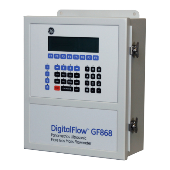
GE DigitalFlow GF868 Programming Manual
Ultrasonic flowmeter for flare gas (1-channel)
Hide thumbs
Also See for DigitalFlow GF868:
- Startup manual (80 pages) ,
- Programming manual (152 pages) ,
- Service manual (74 pages)

Subscribe to Our Youtube Channel
Related Manuals for GE DigitalFlow GF868


Summary of Contents for GE DigitalFlow GF868
- Page 1 Measurement & Control Gas Analysis DigitalFlow™ GF868 Ultrasonic Flowmeter for Flare Gas Programming Manual (1-Channel) 910-194P1 Rev. F February 2015...
- Page 3 DigitalFlow™ GF868 Ultrasonic Flowmeter for Flare Gas Programming Manual (1-Channel) 910-194P1 Rev. F February 2015 www.ge-mcs.com ©2015 General Electric Company. All rights reserved. Technical content subject to change without notice.
- Page 4 [no content intended for this page]...
- Page 5 Preface Information Paragraphs Note: These paragraphs provide information that provides a deeper understanding of the situation, but is not essential to the proper completion of the instructions. These paragraphs provide information emphasizing instructions which are essential to proper setup of IMPORTANT: the equipment.
- Page 6 Environmental Compliance Waste Electrical and Electronic Equipment (WEEE) Directive GE Measurement & Control is an active participant in Europe’s Waste Electrical and Electronic Equipment (WEEE) take-back initiative, directive 2012/19/EU. The equipment that you bought has required the extraction and use of natural resources for its production. It may contain hazardous substances that could impact health and the environment.
-
Page 7: Table Of Contents
Contents Chapter 1. Programming Site Data 1.1 Introduction ................... .1 1.2 Using the Keypad. - Page 8 Contents 1.12.1 MODBUS (RS485) Parameters..............31 1.12.2 MODBUS/TCP Parameters .
- Page 9 Contents Chapter 4. Printing Data 4.1 Introduction ..................59 4.2 Print Live Data.
- Page 10 Contents Appendix C. Programming with PanaView C.1 Introduction...................95 C.2 Wiring the RS232 Interface .
-
Page 11: Chapter 1. Programming Site Data
Chapter 1. Programming Site Data Chapter 1. Programming Site Data 1.1 Introduction The Model GF868 flowmeter cannot provide accurate flow rate measurements until the instrument has been properly installed and the basic system and pipe parameters have been programmed into the meter. See the Startup Guide for detailed instructions on performing these tasks. -
Page 12: Using The Keypad
Chapter 1. Programming Site Data 1.2 Using the Keypad The Model GF868 keypad contains 39 keys, that are labeled with their primary (unshifted) functions. In addition, pressing the red [SHIFT] key will access the secondary functions assigned to most of the keys. The complete keypad is illustrated in Figure 1 and a detailed description of both the unshifted and shifted functions for each of the 39 keys is listed in Table 1 on page 3. - Page 13 Chapter 1. Programming Site Data Table 1: Model GF868 Key Functions Unshifted Function Shifted Function Software Function Keys - press to select the functions None displayed directly above them in the option bar. These keys apply only to the left pane of the display screen. Software Function Keys - press to select the functions None displayed directly above them in the option bar.
- Page 14 Chapter 1. Programming Site Data Table 1: Model GF868 Key Functions (cont.) Unshifted Function Shifted Function Log Key - use to set up logs. See page 49 for details. Use to enter the letter X. Print Key - use to print live measurements, log files and Use to enter the letter R.
- Page 15 Chapter 1. Programming Site Data Table 1: Model GF868 Key Functions (cont.) Unshifted Function Shifted Function Five Key - use to enter the number 5. Use to enter the letter M. Six Key - use to enter the number 6. Use to enter the letter N.
-
Page 16: Obtaining On-Line Help
Chapter 1. Programming Site Data 1.3 Obtaining On-line Help A context-sensitive, on-line help system is programmed into every Model GF868 flowmeter. On-line help, which displays additional information related to the current task, may be accessed at any time by pressing the [HELP] key on the keypad. -
Page 17: Using The Console Control Keys
Chapter 1. Programming Site Data 1.4 Using the Console Control Keys The Model GF868 has four console control keys, which are located on the left side of the keypad. Use these keys, which are described and pictured in Table 1 on page 3, as follows: 1.4.1 Audio Alarm Volume Use the top console control key to adjust the audio alarm volume. -
Page 18: Entering Programming Mode
Chapter 1. Programming Site Data 1.5 Entering Programming Mode Use the keypad, as described in the previous section, to navigate through the User Program. The menu map may be followed in sequence, or the [ and [ keys may be used to scroll through the prompt screens. The [ key may be used to delete the last alphanumeric character that was entered from the keypad. -
Page 19: Activating The Channel
Chapter 1. Programming Site Data 1.6 Activating the Channel submenu permits selection of the desired measurement method. While following the programming ACTIV instructions, refer to Figure 11 on page 87. 1. Enter the submenu by pressing at the prompt. ACTIV [F1] User PROGRAM 2. -
Page 20: Entering System Data
Chapter 1. Programming Site Data 1.7 Entering System Data 1. At the User Program screen, press the function key to program the submenu. [F2] SYSTM 2. Enter a Site Label of up to 9 characters and press . (While taking measurements, the site label will appear on [ENT] the locator bar.) 3. -
Page 21: Entering Totalizer Data
Chapter 1. Programming Site Data 1.7.3 Entering Totalizer Data 10. Use the [F1]-[F4] and [ keys to select the Totalizer Units. 11. Use the keys to select the Total Decimal Digits (the desired number of digits to the right of the decimal [F1]-[F4] point) in the totalized flow display. -
Page 22: Entering Pipe Data
Chapter 1. Programming Site Data 1.8 Entering Pipe Data Enter the transducer and pipe parameters using the submenu. While following the programming instructions, refer PIPE to Figure 11 on page 87. To program this menu, complete the following steps: 1. At the User (or Channel) Program screen, press to program the submenu. -
Page 23: Path Length
Chapter 1. Programming Site Data 1.8.4 Path Length = inch or 5. Press [F1] [F2] = feet to select the units. Then, enter the Path Length (P) of the ultrasonic signal. Press . (The meter will only accept values from 1/8 to 900 in.) [ENT] Note: The factory has calculated both the transducer signal path length and the transducer signal axial length... -
Page 24: Setting Up Inputs/Outputs
Chapter 1. Programming Site Data 1.9 Setting Up Inputs/Outputs Set up the GF868’s inputs and outputs using the four options in the submenu. While following the programming instructions, refer to Figure 12 on page 88. • ERROR - program the meter’s response during an error condition •... -
Page 25: Setting Up Analog Outputs
Chapter 1. Programming Site Data 1.9.2 Setting Up Analog Outputs The Model GF868 has two built-in analog outputs, which are assigned to Slot 0 . Also, a variety of option cards may be installed in the six expansion slots. See Chapter 1, Installation, of the Startup Guide for a complete description of the available option cards. -
Page 26: Option Card Alarms
Chapter 1. Programming Site Data 1.9.3 Option Card Alarms 1. Use the and [ and the [F1]-[F4] keys to select the desired slot number. 2. Use the keys to set up alarm relays A, B, or C, respectively. [F1]-[F3] Note: The set up of alarm A is used as an example. -
Page 27: Setting Up The Totalizer/Frequency Outputs
Chapter 1. Programming Site Data 1.9.4 Setting Up the Totalizer/Frequency Outputs Press [F1]-[F4] to set up outputs A, B, C or D, respectively. = OFF to disable output A and return to the previous prompt, or press = TTLZR to 2. -
Page 28: Setting Up The Analog Inputs
Chapter 1. Programming Site Data 1.9.5 Setting up the Analog Inputs to set up input A or [F2] to set up input B. 1. Press [F1] Note: The set up of input A is used as an example in this manual. Identical procedures would be used to set up input B. -
Page 29: Setting Up Rtd Inputs
Chapter 1. Programming Site Data 1.9.6 Setting up RTD Inputs Option cards with RTD inputs have a temperature range of –100° to 350°C. Complete the following steps to set up the two RTD inputs of an option card installed in Slot x: 1. -
Page 30: Setting Up Temperature And Pressure Inputs
Chapter 1. Programming Site Data 1.9.8 Setting Up Temperature and Pressure Inputs The Model GF868 can use either fixed temperature and pressure quality values or live measurement inputs to calculate standard volumetric or mass flow. Complete the following steps to configure these inputs: 1. - Page 31 Chapter 1. Programming Site Data 1.9.8b Entering the Pressure Input (cont.) • If you selected SLOT X, a. Press to select input A or press to select input B.The inputs were labeled during setup. [F1] [F2] b. Enter the Base Pressure (standard) value for the process, and press the key.
-
Page 32: Entering Setup Data
Chapter 1. Programming Site Data 1.10 Entering Setup Data The signal limits and response times for the Model GF868 are specified using the submenu. While following the SETUP programming instructions, refer to Figure 13 on page 89. The following four submenus are included in this section: •... -
Page 33: Setting Transducer Signal Limits
Chapter 1. Programming Site Data 1.10.1 Setting Transducer Signal Limits Use this option to set the limits for the incoming signal and other parameters affecting the transducer signal. For example, the programmed signal strength low limit may be used to determine the trigger point for an alarm. CAUTION! The SIGNL default settings are suitable for most applications. - Page 34 Chapter 1. Programming Site Data 1.10.1 Setting Transducer Signal Limits (cont.) The amplitude discriminator measures the size of the transducer signal received by the Model GF868. The default value for this parameter is 14 and values from 0 to 100 are acceptable. The error message appears when E5: AMPLITUDE the amplitude discriminator falls below the programmed...
- Page 35 Chapter 1. Programming Site Data 1.10.1 Setting Transducer Signal Limits (cont.) If the burst mode is set to Skan/Measure (S/M), the meter switches from Skan to Measure Mode when Delta T is less than the value. DO NOT change this value unless advised to do so by the factory. The default value for this M>S_Switch parameter is 50 sec and values from 0 to 250 sec are acceptable.
-
Page 36: Setting Response Time
Chapter 1. Programming Site Data 1.10.1 Setting Transducer Signal Limits (cont.) Table 2: Default Values and Limits for SETUP Parameters Parameter Default Value Low Limit High Limit Signal Low Limit Cor. Peak Limit Velocity Low Limit -300.0 ft/sec (- 85 m/sec) -500 ft/sec (-150 m/sec) +500 ft/sec (+150 m/sec) Velocity High Limit... -
Page 37: Initializing The System
Chapter 1. Programming Site Data 1.10.3 Initializing the System Use this option to initialize (reset) many of the parameters within the SETUP menu to their default values. These parameters include: Signal Low Limit, Correlation Peak Limit, Velocity Low and High Limits, Acceleration Limit, Amplitude Discrimination Low, Amplitude Discrimination High, Delta T Offset, Skan T Offset, % of Peak and XMIT Sample Size. - Page 38 Chapter 1. Programming Site Data 1.10.4 Setting Advanced Parameters (cont.) 1.10.4b Edit K Factors 1. Press [F2] = MULTK to enter the MultiK option. = YES to enable Multiple K-factors. 2. Press to disable or [F1] = NO [F2] • , the GF868 returns to the Advanced Features prompt.
-
Page 39: Setting The Clock
Chapter 1. Programming Site Data 1.11 Setting the Clock Use the submenu to enter the current date and time. Refer to Figure 13 on page 89. CLOCK 1. To program the submenu, press [ and at the initial User Program. CLOCK [F2] 1.11.1 Setting the Date... -
Page 40: Setting Up Serial Communications
RS232, MODBUS, Ethernet and MODBUS/TCP communications port parameters COMM and to enter a network identification number. A network identification number is required to use the GE Instrument Data Manager or PanaView software. While following the programming instructions, refer to the menu map in Figure 13 on page 89. -
Page 41: Modbus (Rs485) Parameters
Chapter 1. Programming Site Data 1.12.1 MODBUS (RS485) Parameters If your GF868 does not include an option card for MODBUS communications, you have completed programming the COMM submenu. However, if you have installed a MODBUS option card, the following additional prompts appear. 1. -
Page 42: Modbus Register Map
Chapter 1. Programming Site Data Procedure Options After completing the above steps, the meter returns to the . Continue as follows: User Program • To continue programming the meter, refer to the menu maps in Appendix A and navigate to the desired menu. Then, proceed to the appropriate section of this manual for instructions. - Page 43 Chapter 1. Programming Site Data Table 4: MODBUS Registers for a 1-Channel GF868 MODBUS Scaling Reg # Hex Addr Description (decimal places) Size in Bytes 2 (16 bit signed) 1” Clear Ch1 Totalizers” Not Used 2 (16 bit signed) Velocity 4 (2 16-bit int) Act Volumetric #Q DIGITS...
-
Page 44: Saving Site Data
Chapter 1. Programming Site Data 1.13 Saving Site Data The currently programmed site data may be stored in the Model GF868’s non-volatile memory by saving it as a site file. Up to ten site file names, consisting of up to five characters each, may be stored at any given time. While following the programming instructions, refer to Figure 13 on page 89. -
Page 45: Activating Security
Chapter 1. Programming Site Data 1.15 Activating Security In order to prevent unauthorized tampering with the flowmeter’s programming, the Model GF868 is equipped with a security feature that locks out the following menus: • Program Menu [PROG] • Calibration Menu [CAL] •... - Page 46 Chapter 1. Programming Site Data 1.15.1 Procedure Options After completing the above steps, the meter returns to the User Program prompt. Continue as follows: • To continue programming the meter, refer to the menu maps in Appendix A and navigate to the desired menu. Then, proceed to the appropriate section of this manual for instructions.
-
Page 47: Chapter 2. Displaying Data
Chapter 2. Displaying Data Chapter 2. Displaying Data 2.1 Introduction This chapter explains how to display measurement data in various formats. Each of the two display screen panes may be programmed independently. Note: The instructions in this chapter assume that the left display pane is active. If the right display pane is active, simply change all designations to [F1]-[F4]... -
Page 48: The Big Submenu
Chapter 2. Displaying Data 2.2 The BIG Submenu format, which is the Model GF868’s default power up format, displays one measurement in large print. To select the format and the measurement to display in this format, follow the instructions in this section. Upon power up, a standard measurement mode display (similar to the one shown below) appears. -
Page 49: The Dual Submenu
Chapter 2. Displaying Data 2.3 The DUAL Submenu format displays two measurements simultaneously in normal print. To select the format and the DUAL DUAL measurements to display in this format, follow the instructions in this section. Upon power up, a standard measurement mode display (similar to the one shown below) appears in format. -
Page 50: Using The Graph Format
Chapter 2. Displaying Data 2.4.2 Using the GRAPH Format While viewing data in the GRAPH format, the function keys are programmed to permit a variety of actions. These options are described in detail below. , [ and 1.23 Ft/s 10:16 ... -
Page 51: The Log Submenu
Chapter 2. Displaying Data 2.5 The LOG Submenu submenu permits the display of the data in a log file either graphically or numerically. Although the Model GF868 can display all of the data in a log file, screen size limitations prevent the simultaneous display of the complete log file. -
Page 52: Numeric Format
Chapter 2. Displaying Data 2.5.2 Numeric Format The Model GF868 can log up to three parameters simultaneously. Each set of data values is called a record, and up to 120 consecutive records can be stored in a page. A log file can consist of up to 120 pages. The numeric log display, which shows one record at a time, includes the following components: •... -
Page 53: Graphical Format
Chapter 2. Displaying Data 2.5.3 Graphical Format After choosing PLOT at the FORMAT prompt, the programming sequence continues as follows: 5. Enter a maximum value for the Y-axis (vertical) scale that is larger than the maximum expected reading. Press [ENT] 6. -
Page 54: Displaying The Transducer Signal
Chapter 2. Displaying Data 2.5.3 Graphical Format (cont.) In the typical graphical display shown, the first logged parameter (VEL) is shown to the left of the y-axis and there is a message line below the graph that initially indicates the starting date and time of the current page. Notice that most of the locator bar has been replaced by a status line in standard video that shows the value, units and time of the record at the current cursor location. - Page 55 Chapter 2. Displaying Data Displaying the Transducer Signal (cont.) Note: If the burst technique was selected in the menu, the prompt does not appear and the Skan ACTIV Signal to Display Measure type signals are not available. To access these signals, the burst technique must be selected.
- Page 56 Chapter 2. Displaying Data Displaying the Transducer Signal (cont.) In addition to the functions available on the option bar, some of the numeric keys are used to specify which transducer signal is displayed and to scale the resulting graph. Table 11 lists these functions. Table 11: Numeric Key Functions Function Scroll down the transducer signal list...
-
Page 57: Setting The Lcd Backlight
Chapter 2. Displaying Data 2.7 Setting the LCD Backlight Use the submenu to specify the number of minutes the LCD display backlight remains on before it is BACKL automatically turned off. Press the appropriate side of the [SCREEN] key to activate the desired pane of the display screen, then proceed as follows: Note: For this discussion, it is assumed that the left pane of the display screen is active. - Page 58 Chapter 2. Displaying Data [no content intended for this page] DigitalFlow™ GF868 Programming Manual (1-Channel)
-
Page 59: Chapter 3. Logging Data
Chapter 3. Logging Data Chapter 3. Logging Data 3.1 Introduction This chapter explains how to use the Model GF868’s data logging capability. The menu, which is accessed by pressing the [LOG] key on the keypad, is divided into four submenus: •... -
Page 60: Creating A Standard Log
Chapter 3. Logging Data 3.2 Creating a Standard Log Use the submenu to create a new standard log and to select the parameters to log, the log start time and date, the log end time and date, and the time increment. Also, any log file already stored in memory may be inspected and/or changed. -
Page 61: Log Type
Chapter 3. Logging Data Creating a Standard Log (cont.) Refer to Chapter 3, Diagnostics, of the Service Manual for a discussion of the many parameters accessible using the DIAG option. Note: The units assigned to the parameters in Table 12 on page 50 are those selected in the User Program ( SYSTM submenu). -
Page 62: Start Date Prompt
Chapter 3. Logging Data 3.2.3 START DATE Prompt 11. Press [F1] to accept the displayed Start Date or press [F2] to enter a different start date. To start logging today, press [F3] • was selected, proceed to step 12 for a non-circular log or to step 13 for a circular log. TODAY •... -
Page 63: Duration Prompt
Chapter 3. Logging Data 3.2.6 DURATION Prompt If a circular log was specified, the programming sequence continues here after the log start time and/or start date is entered. 14. Press and enter a log duration in hours or press and enter a log duration in days. When the desired value [F1] [F2] has been entered, press... -
Page 64: Checking The Memory
Chapter 3. Logging Data 3.3 Checking the Memory Use the submenu to verify that the available log memory is sufficient for the desired log. If the expected amount of logged data will exceed the remaining memory capacity, the Model GF868 suggests that some old logs be cleared to make room for the new log. -
Page 65: Stopping A Log
Chapter 3. Logging Data 3.4 Stopping a Log Use the submenu to terminate a logging process that is currently active. Press the appropriate side of the STOP [SCREEN] key to activate the desired pane of the display screen, and complete the following steps: 1. -
Page 66: Creating An Error Log
Chapter 3. Logging Data 3.5 Creating an ERROR Log Use the submenu to create a new error log and to select the logging parameters. An error log updates every 5 ERROR seconds (when the display updates), but only if a new error condition occurs. Error logs have a fixed length of 2 pages and contain sixty records per page. -
Page 67: Log Type
Chapter 3. Logging Data Creating an ERROR Log (cont.) In addition, refer to Chapter 3, Diagnostics, of the Service Manual for a discussion of the many parameters accessible using the DIAG option. Note: The units assigned to the parameters in Table 13 on page 56 are those selected in the User Program ( SYSTM submenu). -
Page 68: Start Date Prompt
Chapter 3. Logging Data 3.5.3 START DATE Prompt 11. Press [F1] to accept the displayed Start Date or press [F2] to enter a different start date. To start logging today, press [F3] • was selected, you have finished setting up the error log. Proceed to Procedure Options below. TODAY •... -
Page 69: Chapter 4. Printing Data
Chapter 4. Printing Data Chapter 4. Printing Data 4.1 Introduction The Model GF868 flowmeter has the capability to print any of the data stored in its memory using the built-in RS232 communications port. In order to use the function, the RS232 port must be connected to a printer with a serial port input. -
Page 70: Print Live Data
Chapter 4. Printing Data 4.2 Print Live Data Use the submenu to print live measurement data, as it is collected. The data may be printed in either numeric or DATA graphical format, with a user specified time increment. Make sure that a printer has been properly set up before proceeding with this section. IMPORTANT: To print live measurement data, refer to Figure 15 on page 91, and complete the following steps: 1. - Page 71 Chapter 4. Printing Data 4.2.1 Numeric Format (cont.) 5. Use the [, [ and [F1]-[F4] keys to select the second parameter to be printed. 6. Use the [, [ and keys to select the third parameter to be printed. [F1]-[F4] 7.
-
Page 72: Graphical Format
Chapter 4. Printing Data 4.2.2 Graphical Format To print live data in graphical format, continue as follows: 8. Use the [, [ and keys to select the first parameter to be printed. See Table 15 for a list of the available [F1]-[F4] options. -
Page 73: Printing Logs
Chapter 4. Printing Data 4.3 Printing Logs Use the submenu to print logged measurement data, from a log file in the meter’s memory. The data may be printed in either numeric or graphical format, with a user specified time increment. Make sure that a printer has been properly set up before proceeding with this section. -
Page 74: Graphical Format
Chapter 4. Printing Data 4.3.2 Graphical Format After the graphical format (and starting page and number of pages, if applicable) is chosen, complete the following additional steps: 7. Enter the desired maximum value for the Y (vertical) axis and press [ENT] Note: Enter a value that is larger than the largest logged measurement value. -
Page 75: Print Site File
Chapter 4. Printing Data 4.4 Print Site File Use the submenu to print the data in a site file that was set up and saved as described in Chapter 1, Programming PROG Site Data. To print a site file, refer to Figure 15 on page 91 and complete the following steps: Make sure that a printer has been properly set up before proceeding with this section. -
Page 76: Stop Printing
Chapter 4. Printing Data 4.5 Stop Printing Use the submenu to terminate the printing of live, logged or site data. To stop any active printing activity, see STOP Figure 15 on page 91, and complete the following steps: Make sure that a printer has been properly set up before proceeding with this section. IMPORTANT: 1. -
Page 77: Printing Signal Array Data
Chapter 4. Printing Data 4.7 Printing Signal Array Data Use the submenu to print signal array data, to help diagnose certain problems. To print the signal data, see SGNLS Figure 15 on page 91 and complete the following steps: Make sure that a printer has been properly set up before proceeding with this section. IMPORTANT: 1. -
Page 78: Printing Rtd Data
Chapter 4. Printing Data Printing Signal Array Data (cont.) The data printed using the submenu consists of 1024 lines, each of which lists the following three values: SIGNL • - this is the printout line number, which locates the data point within the complete body of data. Index •... -
Page 79: Chapter 5. Clearing Data
Chapter 5. Clearing Data Chapter 5. Clearing Data 5.1 Introduction This chapter explains how to purge the Model GF868’s memory of various measurement totals and/or files. The Clear Menu, which is accessed by pressing the [CLR] key on the keypad, is divided into three submenus: •... -
Page 80: Reset Totals
Chapter 5. Clearing Data 5.2 Reset Totals submenu permits the user to reset volumetric totals to zero and to reset the stopwatch totalizer. Press the TOTAL appropriate side of the [SCREEN] key to activate the desired pane of the display screen, and complete the following steps: 1. -
Page 81: Deleting Site Files
Chapter 5. Clearing Data 5.3 Deleting Site Files Use the submenu to clear site files from the GF868’s memory. Use the key to activate the desired display SITE [SCREEN] pane, and complete the following steps: 1. To access the Clear Menu, press the key. -
Page 82: Deleting Log Files
Chapter 5. Clearing Data 5.4 Deleting Log Files Use the submenu to clear log files from the Model GF868’s memory. Press the appropriate side of the [SCREEN] to activate the desired pane of the data display screen, and complete the following steps: 1. -
Page 83: Chapter 6. Serial Communications
The first step is to connect the built-in RS232 port in the GF868 to one of the serial ports (COM1 or COM2) on the personal computer. Table 17 lists the standard cables available from the factory for this purpose. Table 17: GE Serial Cables Part Number... -
Page 84: Checking The Gf868 Baud Rate
Chapter 6. Serial Communications 6.3 Checking the GF868 Baud Rate For successful serial communications, the GF868 and the personal computer must be set up to send/receive data at the same speed. To verify or change the baud rate setting of the GF868, proceed as follows: Access the User Program, by pressing the key on the keypad. -
Page 85: Setting Up The Terminal Software And Transferring Data
Chapter 6. Serial Communications 6.4 Setting Up the Terminal Software and Transferring Data Specific instructions are given in this manual for communicating with personal computers running under either the Windows 3.X (below) or Windows 9X/NT (page 76) operating systems. Proceed to the appropriate section for detailed set up procedures. -
Page 86: Windows 9X/Nt Systems
Chapter 6. Serial Communications 6.4.2 Windows 9X/NT Systems Windows 9X/NT systems use a program called Hyperterminal to access the serial ports. To set up serial communications with a personal computer running under Windows 95, Windows 98 or Windows NT, make sure the GF868 is powered on and complete the following steps: 1. -
Page 87: The Optional Rs485 Serial Interface
6.5 The Optional RS485 Serial Interface Although the standard RS232 serial interface included with the Model GF868 is adequate for most applications, GE offers an optional RS485 serial interface upgrade for special situations. The Model GF868 is easily modified to provide RS485 communications, and this section describes the wiring and use of the special RS232 to RS485 converter. -
Page 88: Point-To-Point Wiring
Chapter 6. Serial Communications 6.5.2 Point-To-Point Wiring Standard factory wiring of the RS485 serial interface is configured for point-to-point wiring. That is, a single Model GF868 may be wired directly to a single personal computer. To connect the RS485 serial interface, refer to Figure 9 on page 77 and complete the following steps: Note: For compliance with the European Union’s Low Voltage Directive, a transparent plastic shroud protects the electrical connections. -
Page 89: Multi-Point Wiring
Chapter 6. Serial Communications 6.5.3 Multi-Point Wiring The standard point-to-point wiring configuration for the serial interface converter may be modified to permit the use of a multi-point wiring arrangement. In a multi-point RS485 system, one flowmeter (the master) is connected to the personal computer, while a number of additional flowmeters (the slaves) are chained together and connected to the master flowmeter. - Page 90 Chapter 6. Serial Communications 6.5.3 Multi-point Wiring (cont.) 6.5.3a Reconfiguring a Serial Interface Converter (cont.) Plastic Case Mounting Screw Screwdriver DB9 Connector Figure 10: Opening the Converter Case Table 19: Switch Assembly Settings Position # Point-To-Point Multi-Point 7. Reassemble the serial interface converter and secure it to the mounting bracket with the two mounting screws. 8.
- Page 91 Chapter 6. Serial Communications 6.5.3b Wiring the System After the serial interface converters have been configured for multi-point operation, the system can be wired. 1. Using twisted-wire pairs, connect the XMT+ terminals of all the flowmeters together and connect the XMT– terminals of all the flowmeters together.
-
Page 92: Setting Up An Ethernet Connection
Chapter 6. Serial Communications 6.6 Setting Up an Ethernet Connection A modified GF868 can use the Ethernet interface to communicate with an internal network. An optional Ethernet card with a unique MAC (IP) address (installed only in slots 5 or 6) includes an RJ45 connector. To connect the Ethernet-enabled GF868 to the network, insert the jack of an RJ45 cable into the RJ45 connector, route the cable through the bottom of the GF868, and wire the other end of the cable to the LAN according to the manufacturer’s instructions. -
Page 93: Setting Up A Modbus/Tcp Connection
Chapter 6. Serial Communications 6.7 Setting Up a MODBUS/TCP Connection A modified GF868 can use the MODBUS/TCP interface to communicate with an internal network. An optional MODBUS/TCP card with a unique MAC (IP) address (installed only in slots 5 or 6) includes an RJ45 connector. To connect the MODBUS/TCP-enabled GF868 to the network, insert the jack of an RJ45 cable into the RJ45 connector, route the cable through the bottom of the GF868, and wire the other end of the cable to the LAN according to the manufacturer’s instructions. - Page 94 Chapter 6. Serial Communications [no content intended for this page] DigitalFlow™ GF868 Programming Manual (1-Channel)
-
Page 95: Appendix A. Menu Maps
Appendix A. Menu Maps Appendix A. Menu Maps DigitalFlow™ GF868 Programming Manual (1-Channel) - Page 96 [no content intended for this page] DigitalFlow™ GF868 Programming Manual (1-Channel)
-
Page 97: Appendix A. Menu Maps
Appendix A. Menu Maps NOTE: Plain text represents prompt area messages and boxed text represents option bar choices. Fx represent function keys to select option bar choices. PROG PROGRAM status ACTIV SYSTM PIPE TOTALIZER UNITS (English) (Metric) SITE LABEL See Figure A-2 Site status TRANSDUCER NUMBER SITE MESSAGE... - Page 98 PROG PROGRAM status ACTIV SYSTM PIPE SETUP CLOCK COMM SAVE RECLL SECUR See Figure A-1 See Figure A-1 See Figure A-1 See Figure A-3 See Figure A-3 See Figure A-3 See Figure A-3 See Figure A-3 See Figure A-3 ERROR OPTN ZERO ERROR HANDLING...
-
Page 99: Appendix A. Menu Maps
Appendix A. Menu Maps PROG PROGRAM status ACTIV SYSTM PIPE SETUP CLOCK COMM SAVE RECLL SECUR See Figure A-1 See Figure A-1 See Figure A-1 See Figure A-2 SET UP BAUD RATE 1200 2400 SIGNL AVRG INIT ADVAN Press YES to Default 4800 9600 19200... -
Page 100: Appendix A. Menu Maps
Appendix A. Menu Maps DISP DISPLAY FORMAT DUAL GRAPH SIGNL BACKL SLEEP NAME LCD SLEEP MODE LOG1 LOG2 LOG3 LOG4 Backlight timeout GRAPH VARIABLE FORMAT VOLUM MDOT PLOT (*available only if Mass Flow (static)? = YES) Y AXIS MAX Y RANGE Signal to Display TIME INCREMENT +only... -
Page 101: Appendix A. Menu Maps
Appendix A. Menu Maps PRNT PRINT DATA PROG STOP PRNTR SGNLS RTDs FORMAT FORMAT PLOT PLOT 1st value printed NAME STOP PRINTING SIGNAL ARRAY VOLUM +TOTL –TOTL LOG1 LOG2 LOG3 LOG4 SIGNL CROSS BOTH MDOT +MASS –MASS DIAG (log>1 page) (log=1 page) 1st page (NUM option) (PLOT option) -
Page 102: Appendix A. Menu Maps
Appendix A. Menu Maps LOGGING CLEAR STOP ERROR TOTAL SITE X/120 Pages FREE NAME CLEAR TOTALS SITE NAME NAME Y Pages PENDING LOG1 LOG2 LOG3 LOG4 SITE1 SITE2 SITE3 SITE4 LOG1 LOG2 LOG3 LOG4 Stop Logging ? CLEAR SITE NAME CLEAR NAME NAME LOG1... -
Page 103: Appendix B. Data Records
Appendix B. Data Records Appendix B. Data Records B.1 Option Cards Installed Whenever an option card is installed in one of the Model GF868’s expansion slots, record the type of card and any additional setup information in the appropriate row of Table 20. Table 20: Option Cards Installed Slot # Type of Option Card... -
Page 104: Initial Setup Data
Appendix B. Data Records B.2 Initial Setup Data After the Model GF868 flowmeter has been installed, some initial setup data must be entered using the User Program, prior to operation. Record that information in Table 21. Table 21: Initial Setup Data General Information Model # Reference... -
Page 105: Appendix C. Programming With Panaview
Appendix C. Programming with PanaView C.1 Introduction The PanaView™ graphical user interface offers interactive communications between Windows-based PCs and GE instruments compatible with the company’s IDM protocol, such as the GF868 ultrasonic gas flowmeter. PanaView is compatible with 32-bit Windows operating systems such as Windows 98SE, NT 4.0 (with Service Pack 6), 2000, XP and ME. -
Page 106: Setting Up The Communications Port
C.3 Setting Up the Communications Port Use the steps below to establish communications with the GF868. 1. Open the “New Meter Browser” window and expand the network tree. Then, highlight the My Computer(Name) branch by clicking on it. 2. Pull down the “Edit” menu by clicking on it in the menu bar. 3. - Page 107 Appendix C. Programming with PanaView Setting Up the Communications Port (cont.) 4. Click on the “Communications Port” option to select it. The Setup Communications screen appears similar to Figure 18. Figure 18: Setup Communications Screen 5. Open the Protocol menu (the first of the drop-down menus) and click on IDM. 6.
-
Page 108: Setting Up Ethernet Communications
Appendix C. Programming with PanaView C.3.1 Setting up Ethernet Communications If you have selected TCP/IP in step 6 on the previous page, the Setup Communications window appears similar to Figure 19. Figure 19: Setup Communications for TCP/IP 1. Type in the desired Name and Timeout (in milliseconds). 2. -
Page 109: Adding The Gf868
Appendix C. Programming with PanaView C.4 Adding the GF868 To add the GF868 on the IDM-configured communications port, complete the following steps: 1. Highlight the communication port to which the meter will be added by clicking on it, and then open the “Edit” menu on the menu bar (if the communication port is not highlighted first, the “New Meter”... - Page 110 Appendix C. Programming with PanaView Adding the GF868 (cont.) The Network ID number must match the Network ID programmed in the meter’s Communications menu. IMPORTANT: If the initialization is successful, the Meter Browser shows a listing similar to Figure 22. Figure 22: The Updated Network Tree Note: The model number and version that appear will vary with your particular meter and software version.
-
Page 111: Editing Meter Properties
Appendix C. Programming with PanaView C.5 Editing Meter Properties Through PanaView, you can edit the properties of your GF868. You can: • Set the meter clock, or synchronize it with the PC clock • Read, plot and save transducer signals •... - Page 112 Appendix C. Programming with PanaView Editing Meter Properties (cont.) The window appears similar to Figure 25. To perform a specific task, refer to the appropriate section on the following pages. • Setting the Meter Clock (page 103) • Reading Transducer Signals (page 104) •...
-
Page 113: Setting The Meter Clock
Appendix C. Programming with PanaView C.5.1 Setting the Meter Clock The meter’s Time may be reset in three different ways: • manually enter the time and date in the text box, or • click on the option button to have PanaView set the time and date to the current PC setting, or [Sync to PC] •... -
Page 114: Reading Transducer Signals
Appendix C. Programming with PanaView C.5.2 Reading Transducer Signals To read a Signal from the meter: 1. Click on the Read Signals button. (If the meter is a multi-channel instrument, open the Channel drop-down menu and click on the desired channel.) After a moment, the Properties window appears similar to Figure 27. Figure 27: Active Signal Options 2. -
Page 115: Plotting Transducer Signals
Appendix C. Programming with PanaView C.5.3 Plotting Transducer Signals To plot the selected signal, click on Plot. A graphical window opens, as shown in Figure 28. Figure 28: Signal Graph Window C.5.4 Saving Transducer Signals To save the raw signal, click Save. A window opens similar to Figure 29. Enter the desired name, and click Save to save the signal as a text file. -
Page 116: Handling Site Files
Appendix C. Programming with PanaView C.5.6 Handling Site Files To access site files, click on the Site Files button in the Properties window. The Site File Operations window (shown in Figure 30) opens. Figure 30: The Site File Operations Window C.5.6a Saving an Existing Site to the Meter To save an existing site to the meter: 1. - Page 117 Appendix C. Programming with PanaView C.5.6b Saving a New Site to the Meter To save a new site to the meter: 1. Select the radio button for New and click on the Save Site to Meter button. 2. A window opens similar to Figure 32. Enter the desired name, and click [OK] Figure 32: Site Name Entry Window 3.
- Page 118 Appendix C. Programming with PanaView C.5.6e Saving a Site in Text Form To store the data from a site file as a text file for display or printout: 1. Highlight the site in the left pane. (See Figure 30 on page 106.) 2.
-
Page 119: Changing Meter Settings
Appendix C. Programming with PanaView C.6 Changing Meter Settings Through PanaView, GF868 users can handle remote programming of the meter. They can: • Program and change a meter’s operating parameters; • Set up, start, and stop logs; • Calibrate and test inputs and outputs; •... - Page 120 Appendix C. Programming with PanaView Changing Meter Settings (cont.) 4. From the meter tree, expand the Edit Functions option. The window now appears similar to Figure 35, with a list of available menus. The menus listed are those available on the meter. Figure 35: Meter Tree with Edit Functions Option 5.
- Page 121 Appendix C. Programming with PanaView Changing Meter Settings (cont.) 6. To enter a particular option: a. Highlight and double-click on the desired option in the left pane. Figure 37 shows the first entry (Transducer Number) in the Pipe parameters option. The title above the center pane lists the current entry, while the center pane displays the available selections for that entry.
- Page 122 Appendix C. Programming with PanaView Changing Meter Settings (cont.) Figure 38: Site Edit Menu with Current Settings 7. When you have completed entering parameters in a given option, click to close the option. You can then [Exit Page] double-click on another option, or click [Close] to close the window.
-
Page 123: Appendix D. Foundation Fieldbus Communications
Appendix D. Foundation Fieldbus Communications Appendix D. Foundation Fieldbus Communications D.1 Optional Measurements Foundation Fieldbus provides a means of communicating with the flowmeter. The patent numbers which apply are 5,909,363 and 6,424,872. This Foundation Fieldbus device supports 6 Analog Input (AI) blocks, which can be configured to supply the following measurements on the network (see Table 22). -
Page 124: Configuration Utility Setup
D.2 Configuration Utility Setup The following is an example setup using National Instruments Configuration Utility v3.1. Figure 39 shows the Configuration Utility with a flowmeter on the network (GE Flow-XMT). Figure 39: Configuration Utility Setup Example Note: The following procedures assume that the device has been placed in the OOS (out-of-service) mode before executing. - Page 125 Appendix D. Foundation Fieldbus Communications Selecting the Desired Measurements (cont.) 4. After the desired measurements have been selected for the PRIMARY and SECONDARY SELECTOR, choose the unit system (UNIT_SELECTOR above the PRIMARY_SELECTOR) that has been programmed in the flowmeter (English or SI).
-
Page 126: Selecting Units For Ai Blocks
Appendix D. Foundation Fieldbus Communications D.4 Selecting Units for AI Blocks To select the units for the individual AI blocks: 1. Double click on the AI block for which you wish to set the units (ANALOG_INPUT_1 or ANALOG_INPUT_2 in the tree under GEFlow-XMT;... -
Page 127: Resetting Instrument Totalizers
Appendix D. Foundation Fieldbus Communications D.5 Resetting Instrument Totalizers To reset the instrument totalizers: 1. Double click on the FLOW transducer block (in the tree under GEFlow-XMT; see Figure 39 on page 114). 2. Select the Others tab and scroll down to the CLEAR_TOTALIZERS listing. 3. -
Page 128: Function Block Application
Appendix D. Foundation Fieldbus Communications D.6 Function Block Application Figure 43 is an example setup using the Function Block Application editor. The flowmeter AI blocks, along with the AO and PID of another device on the network, are displayed. We have connected the AI_1 OUT of the flowmeter to the CAS IN of the AO block. -
Page 129: Appendix E. Foundation Fieldbus Tables
Appendix E. Foundation Fieldbus Tables Appendix E. Foundation Fieldbus Tables Table 23: GE Fieldbus Device Capability, XGX868 Family of Meter Types GF868, GS868, GM868, XGF868i, XGM868i, and Model XGS868i 1 --General Is the Device registered at the Fieldbus Foundation (Yes/No) - Page 130 Appendix E. Foundation Fieldbus Tables Table 23: GE Fieldbus Device Capability, XGX868 Family of Meter Types (cont.) 1.17 Meter Software version (minimum and higher) GF868: GF3S; GM868:GM3Q; GS868: GS3N; GC868: GC4C; XGM868i: Y4DM; XGS868: Y4DS; XGF868i:Y4DF 1.18 Firmware on FF card version 868_GAS_FF_206 1.19...
- Page 131 Appendix E. Foundation Fieldbus Tables Table 23: GE Fieldbus Device Capability, XGX868 Family of Meter Types (cont.) 5 - User Layer General Function Block Application Manufacturer Fieldbus Inc. Function Blocks (list all type, but not including 6 - AI(e), 1 - PID(e), 2 -TB(c), 1 - RB2(e)
- Page 132 Appendix E. Foundation Fieldbus Tables Table 23: GE Fieldbus Device Capability, XGX868 Family of Meter Types (cont.) List by Channel, Unit Code, Enumerated description, and Function Block Type (if Channels XD_SCALE and CHANNEL value applicable) Channel 0 Channel 1 Channel 1 - “Primary Value”/”Secondary Value”...
- Page 133 Appendix E. Foundation Fieldbus Tables Table 23: GE Fieldbus Device Capability, XGX868 Family of Meter Types (cont.) 33026 - thousands of standard cubic meters (changed to 34043) 33037 - millions of actual cubic feet (changed to 34004) 33042 - millions of actual cubic meters...
- Page 134 Appendix E. Foundation Fieldbus Tables Table 23: GE Fieldbus Device Capability, XGX868 Family of Meter Types (cont.) 1357 - cubic feet per minute 1358 - cubic feet per hour 1359 - cubic feet per day 1497 - cubic kilometer per second...
- Page 135 Appendix E. Foundation Fieldbus Tables Table 23: GE Fieldbus Device Capability, XGX868 Family of Meter Types (cont.) 34018 - Millions of Standard cubic feet per second 34019 - Millions of Standard cubic meter per 34020 - Millions of Standard cubic meter per...
- Page 136 Appendix E. Foundation Fieldbus Tables Table 23: GE Fieldbus Device Capability, XGX868 Family of Meter Types (cont.) 34045 - Thousands of Standard cubic meters per hour 34046 - Thousands of Standard cubic meters per minute 34047 - Thousands of Standard cubic meters...
- Page 137 Index ....10 DATA Abbreviations, Volumetric Units ....... 60 Submenu ACTIV .
- Page 138 Index Log File ....... . 49 Header GRAPH ......49 Pages of Memory .
- Page 139 Index Option Card PROG ....... . 16 ........8 Alarms .
- Page 140 ....73 ......15 GE Panametrics Cables Setting Up .
- Page 141 Index ....... . 133 Warranty ZERO ..... . 19 Entering Cutoff Value .
- Page 142 Index DigitalFlow™ GF868 Programming Manual (1-Channel)
- Page 143 AUTHORIZATION NUMBER (RAN), and shipping instructions for the return of the instrument to a service center will be provided. 2. If GE Sensing instructs you to send your instrument to a service center, it must be shipped prepaid to the authorized repair station indicated in the shipping instructions.
- Page 144 Warranty [no content intended for this page] DigitalFlow™ GF868 Programming Manual (1-Channel)
- Page 145 Cable glands of an approved flameproof design are required for Ex d rated equipment. These must be installed according to the manufacturer’s instructions. Where the cable glands are provided by GE, the manufacturer’s instructions, as supplied to GE, will be included in the documentation.
- Page 146 Certification & Safety Statements for GE Infrastructure Products Used in Hazardous Locations August 2014 Special Conditions for Safe Use Consult the manufacturer if dimensional information on any flameproof joint is necessary. Follow the manufacturer’s instructions to reduce the potential of an electrostatic charging hazard.
- Page 147 EC DECLARATION Sensing CONFORMITY DOC-0013, Rev. B GE Sensing 1100 Technology Park Drive Billerica, MA 01821 declare under our sole responsibility that the DigitalFlow™ DF8688 Liquid Ultrasonic Flowmeter DigitalFlow™ GC868 Clamp-On Gas Ultrasonic Flowmeter DigitalFlow™ GF868 Flare Gas Mass Ultrasonic Flowmeter DigitalFlow™...
- Page 150 Customer Support Centers U.S.A. The Boston Center 1100 Technology Park Drive Billerica, MA 01821 U.S.A. Tel: 800 833 9438 (toll-free) 978 437 1000 E-mail: sensing@ge.com Ireland Sensing House Shannon Free Zone East Shannon, County Clare Ireland Tel: +353 (0)61 470200 E-mail: gesensingsnnservices@ge.com An ISO 9001:2008 Certified Company www.ge-mcs.com/en/about_us/quality.html...
Need help?
Do you have a question about the DigitalFlow GF868 and is the answer not in the manual?
Questions and answers