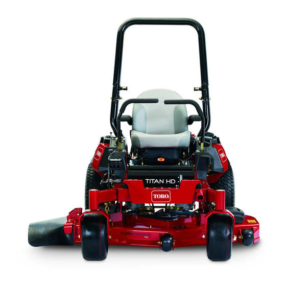
Toro TITAN HD 1500 Operator's Manual
48 in, 52 in, or 60 in riding mower
Hide thumbs
Also See for TITAN HD 1500:
- Operator's manual (88 pages) ,
- Operator's manual (68 pages) ,
- Operator's manual (68 pages)
Table of Contents
Advertisement
Register at www.Toro.com.
Original Instructions (EN)
48in, 52in, or 60in TITAN
1500, 2000, or 2500 Series Riding
Mower
Model No. 74450—Serial No. 400010798 and Up
Model No. 74451—Serial No. 400010798 and Up
Model No. 74452—Serial No. 400010798 and Up
Model No. 74460—Serial No. 400010798 and Up
Model No. 74461—Serial No. 400010798 and Up
Model No. 74462—Serial No. 400010798 and Up
Model No. 74463—Serial No. 400010798 and Up
Model No. 74470—Serial No. 400010798 and Up
Model No. 74471—Serial No. 400010798 and Up
Model No. 74472—Serial No. 400010798 and Up
Model No. 78450—Serial No. 400010798 and Up
Form No. 3405-604 Rev D
®
HD
*3405-604* D
Advertisement
Table of Contents


Need help?
Do you have a question about the TITAN HD 1500 and is the answer not in the manual?
Questions and answers