
Subscribe to Our Youtube Channel
Related Manuals for MARTINDALE VR2250


Summary of Contents for MARTINDALE VR2250
- Page 1 VR2250 VR2250 INSTALLATION ANALYSER MULTIFUNCTION TEST INSTRUMENT USER INSTRUCTION MANUAL Page 1 of 131...
-
Page 2: Table Of Contents
VR2250 TABLE OF CONTENTS 1. SAFETY PRECAUTIONS AND PROCEDURES ..................5 1.1. Forwards ..................................5 1.2. Preliminary Instruction ..............................5 1.3. During Use ................................... 6 1.4. After Use ..................................6 2. GENERAL DESCRIPTION ........................... 7 2.1. Introduction .................................. 7 2.2. Functions ..................................7 3. - Page 3 VR2250 7. AUX: MEASUREMENT WITH EXTERNAL PROBES .................56 7.1. ENVIRONMENTAL PARAMETER AND LEAKAGE CURRENT: REAL TIME MEASUREMENT ......57 7.2. ENVIRONMENTAL PARAMETER AND LEAKAGE CURRENT: RECORDING ............. 59 7.2.1. AUX Basic setting: RECORDER CONFIG ........................59 7.2.2. RECORDING: setting of Typical Configurations ......................61 8.
- Page 4 VR2250 14. TECHNICAL SPECIFICATIONS .......................100 14.1. Technical Features ..............................100 14.1.1. Safety Test functions ..............................100 14.1.2. ANALYSER and AUX functions .............................102 14.2. Standards ................................103 14.2.1. General ..................................103 14.2.2. Safety Test ..................................103 14.2.3. ANALYSER………………………………………………………………………………………………………………………..110 14.2.4. AUX ....................................103 14.3. General Specifications ............................104 14.3.1.
-
Page 5: Safety Precautions And Procedures
(building yards, swimming pools, etc.) and 50V in ordinary places because of the risk of electric shock. Use only cables and accessories approved by Martindale Electric. The following symbols are used in this manual: Caution: refer to the instructions reported in this manual; improper use may damage the apparatus or its components. -
Page 6: During Use
VR2250 Please keep to the usual safety standards aimed at: ♦ Protecting against dangerous currents; ♦ Protecting the instrument against incorrect operations. Only the accessories supplied with the instrument guarantee compliance with the safety standards. Accordingly, they must be in good condition and, if necessary, they must be replaced with identical models. -
Page 7: General Description
VR2250 2. GENERAL DESCRIPTION 2.1. INTRODUCTION Dear Customer, we thank you for your patronage. The instrument you have just purchased will grant you accurate and reliable measurements provided that it is used according to the present manual’s instructions. The instrument was designed to grant the user the utmost safety conditions thanks to a new concept assuring double insulation and over voltage category III. -
Page 8: Preparation For Use
VR2250 3. PREPARATION FOR USE 3.1. INITIAL CONTROL This instrument has been checked mechanically and electrically prior to shipment. All care has been taken to ensure that the instrument reaches you under safe conditions. You are recommended, however, to carry out a rapid check to detect any possible damage which might have been caused during transport. -
Page 9: Calibration
VR2250 CAUTION For recordings (ANALYSIS and AUX function) it is recommended to ALWAYS use the external power supply adapter (optional code MAR####), although the instrument does allow the operator to perform a recording using internal batteries. If during a recording the external power supply... -
Page 10: Instrument Description
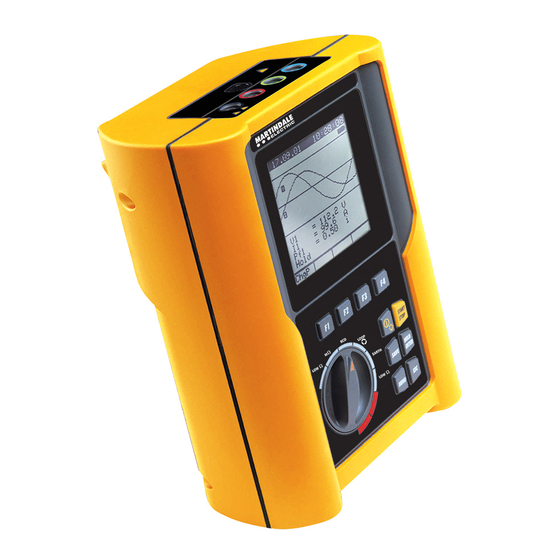
VR2250 4. INSTRUMENT DESCRIPTION LEGEND: Display Function Keys Rotary switch START STOP HOLD SAVE ENTER MENU Multifunction Keys. ON/OFF and backlight key. Press it for a few seconds to switch OFF the ON / OFF instrument, press it briefly to activate the backlight function. -
Page 11: Display Description
VR2250 4.1. DISPLAY DESCRIPTION The display is a graphic module with a resolution of 128 x 128 pixels The first line of the display shows the date and time. If not correct, you can set these according to the procedure described at paragraph 5.2. -
Page 12: Initial Settings
VR2250 5. INITIAL SETTINGS By pressing the MENU key the following screen will be displayed: MENU GENERAL SAFETY TEST MEMORY ANALYZER MEMORY RESET ANALYZER CONFIG RECORDER CONFIG CONTRAST DATE&TIME LANGUAGE ↓ ↑ It’s not possible to enter the MENU during a recording or a Real Time Energy measurement. -
Page 13: Reset
VR2250 5.4. RESET This option re-establishes the initial settings of the instrument in ANALYSER function. The “Current Range” parameter it is not modified by the reset command. The initial settings of the instrument consist of: ANALYZER CONFIG: System: SINGLE Frequency:... -
Page 14: Safety Test Functions
VR2250 6. SAFETY TEST FUNCTIONS 6.1. LOWΩ: CONTINUITY TEST WITH 200mA TEST CURRENT The measurement is performed according to EN 61557-2 and VDE 0413 part 4. CAUTION Before carrying out the continuity test make sure that there is no voltage at the ends of the conductor under test. -
Page 15: Calibrating The Test Leads ("Cal" Mode)
VR2250 6.1.1. Calibrating the test leads ("CAL" Mode) 1. Connect the Red and Black test leads to B1 and B4 input terminals respectively. BLACK Connection of the test leads during calibration procedure. 2. If the test leads supplied with the instrument are not long enough for the measurement you can extend the black cable. - Page 16 VR2250 TEST LEADS Before each measurement always make sure that the calibration is applicable to the test leads in use. During a continuity test, if the resistance value free of calibration (that is the resistance value is less than the calibration offset value) is negative, the symbol is displayed.
-
Page 17: Measurement Procedure
VR2250 6.1.2. Measurement Procedure 1. Select the desired mode by means of the F1 key. 2. Connect the red and black test leads to B1 and B4 input terminals respectively BLAC Connection of the test leads during LOWΩ test. 3. If the cables supplied with the instrument are not long enough for the measurement you can extend the black cable. -
Page 18: Results Of "Rt+" And "Rt-" Modes
VR2250 6.1.4. Results of "RT+" and "RT-" modes if a resistance value Max Resistance value of LOWΩ 05.06.01 R+ or R-. RT+ or RT+ lower than 5Ω detected, 1.07Ω instrument emits Test current double sound signal indicating the positive Duration of the Test... - Page 19 VR2250 In case that: LOWΩ 05.06.01 >R CALIBRATION MEASURED the instrument displays 0.00Ω the screen alongside. ATTENTION: >R CALIBRATION MEASURED 0.00Ω 0.00Ω 219mA 219mA CAL > RES AUTO 0.11Ω FUNC THE PREVIOUS RESULTS CANNOT BE SAVED. value LOWΩ 05.06.01 Resistance...
-
Page 20: Mω: Insulation Resistance Measurement With 50V, 100V, 250V, 500V, 1000V Test Voltage
VR2250 6.2. MΩ: INSULATION RESISTANCE MEASUREMENT WITH 50V, 100V, 250V, 500V, 1000V TEST VOLTAGE These measurement comply with IEC 61557-2 and VDE 0413 part 1. CAUTION Before affecting the insulation test make sure that the circuit under test is not energised and all the loads are disconnected. - Page 21 VR2250 Standard Brief description Test voltage Maximum limit value Systems SELV or PELV 250VDC > 0.250MΩ CEI 64-8/6 Systems up to 500V (Civil installations) 500VDC > 0.500MΩ Systems over 500V 1000VDC > 1.0MΩ Floor and wall insulation in civil installations 500VDC >...
-
Page 22: Results Of "Man" Mode
VR2250 6.2.2. Results of "MAN" mode MΩ 05.06.01 Insulation Resistance At the end of the test if the Insulation resistance is lower than R (see Voltage during the Test Table2) and the 1.07 MΩ instrument generated Duration of the Test... -
Page 23: Results Of "Tmr" Mode
VR2250 6.2.3. Results of "TMR" mode MΩ 05.06.01 Insulation Resistance At the end of the test if the Insulation resistance is lower Voltage during the Test Ω than R (see Table2) 1.07 and the instrument Duration of the Test generated the... -
Page 24: Man" And "Timer" Mode Faulty Cases
VR2250 6.2.4. "MAN" and "TIMER" mode faulty cases If the instrument MΩ 05.06.01 detects the External Ω Power supply adapter -.- - connected to the Disconnect the External Power Supply Adapter instrument, the message along side ---V will be displayed. -
Page 25: Rcd: Test On "A" And "Ac" Rcds Type
VR2250 6.3. RCD: TEST ON "A" AND "AC" RCDS TYPE The test is executed according to IEC61557-6, EN61008, EN61009, EN60947-2 B 4.2.4 and VDE 0413 part 6. CAUTION The automatic check of the RCD features causes the tripping of the RCD itself. - Page 26 VR2250 The F2 key permits to select one of the following rated tripping currents of the RCD (which can be shown cyclically when pressing the key): 10mA. 30mA. 100mA. 300mA. 500mA. The F3 key permits to select the RCD type (which can be shown cyclically when pressing the key): α...
-
Page 27: Tripping Times For The General And Selective Rcds
VR2250 6.3.1. Tripping times for the general and selective RCDs Table of tripping times for I x1, I x2, I x5 and AUTO tests. ∆N ∆N ∆N If the parameters set on the instrument comply with the type of RCD under test (and... -
Page 28: Measurement Procedure
VR2250 6.3.2. Measurement procedure 1. Select the desired test parameter by means of the F1, F2, F3, F4 key. 2. Connect the Red, Green and Black connectors of the three-terminal mains cable or of the split cables to the corresponding input terminals of the instrument B1, B3, B4... - Page 29 VR2250 6.3.2.1. Results of "x½" mode START 4. Press the START key once to execute a test with 0° Current waveform. STOP Press the START key once to execute a test with 180° Current waveform. CAUTION Never disconnect the test leads when the message "MEASURING" is displayed.
- Page 30 VR2250 6.3.2.3. Results of "AUTO" mode 4. Press the START key once to execute the test. The instrument carries out the START STOP following six tests with different values of rated current: 1/2I with 0° current waveform (the RCD shall not trip).
- Page 31 VR2250 6.3.2.4. Results of "RAMP " mode 4. Press the START key once to execute a test with 0° Current waveform. START STOP Press the START key once to execute a test with 180° Current waveform. The instrument generates a leakage current growing step by step for a given time interval.
- Page 32 VR2250 6.3.2.5. Results of “RA " mode 4. Press the START key once: the instrument carries out the test. START STOP CAUTION Never disconnect the test leads when the message "MEASURING" is displayed. The RCD must NOT trip and the instrument emits a double sound 05.06.01...
-
Page 33: Rcd Faulty Cases
VR2250 6.3.3. RCD Faulty cases 6.3.3.1. Connection troubles If the instrument detects 05.06.01 the External Power supply adapter Disconnect the External connected, the - - - Power Supply Adapter instrument will show the FRQ=50.0Hz Ut= ---V message displayed VP-N=230V Vp-PE=230V along side. - Page 34 VR2250 This screen is displayed 05.06.01 when the phase conductor has been - - - reverseded with the neutral one. FRQ=50.0Hz Ut= ---V The instrument does not VP-N=231V VP-PE= perform the test. CHANGE P-N Exchange the red cable Phase and Neutral Conductors are reversed.
- Page 35 VR2250 If a contact voltage U 05.06.01 higher than the selected limit (U ) is detected, the instrument - - - interrupts the test and emits a long sound FRQ=50.0Hz Ut= ---V VP-N=234V VP-PE= 234V signal at the end of the...
- Page 36 VR2250 Ω Using the R function, 05.06.01 if a contact voltage U higher than the selected limit (U ) is 1800 Ω detected the instrument emits a long sound FRQ=50.0Hz VP-N=234V VP-PE= signal at the end of the The instrument does not...
- Page 37 VR2250 If the RCD tripping time 05.06.01 RCD tripping time is bigger is higher than the than the maximum instrument’s measuring measurable time (it >999 limits, the instrument depends on type of test, emits a long sound see following table).
-
Page 38: Loop
LOOP 29.01.04 Z=-----Ω R=-----Ω X=-----Ω IkSTD=----A V1-2= 0V FRQ= 0.0Hz IMP57 Z2Ω FUNZ ZSTD ICAL For further details regarding IMP57 use and technical characteristics please refer to IMP57 user's manual or Martindale Electric web site www.Martindale-Electric.co.uk. Page 38 of 131... -
Page 39: Measurement Procedure And Results Of "P-N" Mode
VR2250 6.4.2. Measurement procedure and results of "P-N" mode 1. Select P-N mode by means of the F1 key. 2. Connect the red, green and Black connectors of the three-terminal mains cable or of the split cables to the corresponding input terminals of the instrument B1, B3, B4. -
Page 40: Measurement Procedure And Results Of "P-P" Mode
VR2250 6.4.3. Measurement procedure and results of "P-P" mode 1. Select P-P mode by means of the F1 key. 2. Connect the Red, Green and Black connectors of the three-terminal mains cable or of the split cables to the corresponding input terminals of the instrument B1, B3, B4... -
Page 41: Measurement Procedure And Results Of "P-Pe" Mode
VR2250 6.4.4. Measurement procedure and results of "P-PE" mode 1. Select P-PE mode by means of the F1 key. 2. Connect the Red, Green and Black connectors of the three-terminal mains cable or of the split cables to the corresponding input terminals of the instrument B1, B3, B4. - Page 42 VR2250 CAUTION Never disconnect the test leads when the message "MEASURING" is displayed. At the end of the test the instrument emits a double sound signal LOOP 05.06.01 Value of phase to Earth Resistance expressed in Ω. indicating that the test is correctly 1.07...
-
Page 43: Measurement Procedure And Results Of " R
VR2250 6.4.5. Measurement procedure and results of " R " mode 1. Select R mode by means of the F1 key. 2. Connect the Red, Green and Black connectors of the three-terminal mains cable or of the split cables to the corresponding input terminals of the instrument B1, B3, B4. -
Page 44: Measurement Procedure And Results Of " " Mode
VR2250 6.4.6. Measurement procedure and results of " " mode mode by means of the F1 key. 1. Select 2. Connect the Red, Yellow and Green connectors of the split cables to the corresponding input terminals of the instrument B1, B2, B3. -
Page 45: Loop Faulty Cases
VR2250 6.4.7. LOOP Faulty Cases If the instrument detects LOOP 05.06.01 the External Power supply adapter Ω - - - Disconnect the External connected, the ---A Power Supply Adapter instrument will show the message displayed FRQ=50.0HZ along side. VP-N=231V VP-PE=230V... - Page 46 VR2250 This screen is displayed LOOP 05.06.01 when the phase conductor has been - - - Ω reversed with the neutral ---A one. The instrument does not FRQ=50.0HZ perform the test. VP-N=231V VP-PE= Exchange the red cable Phase and Neutral CHANGE P-N Conductors are reversed.
- Page 47 VR2250 If a contact voltage U LOOP 05.06.01 higher than the selected limit (U ) is Ω - - - detected the instrument ---A interrupts the test and emits a long sound FRQ=50.0HZ signal at the end of the Message “Ut”: the...
- Page 48 VR2250 Using the " " mode, if LOOP 05.06.01 a Phase to Phase voltage is lower than - - - 100V, the instrument displays the screen FRQ =50.0HZ VR-S=391V indicated alongside. VS-T= VT-R= LOW VOLTAGE T Phase T2 Voltage is lower...
- Page 49 VR2250 In the mode P-P, P-N Message ">199.9" means LOOP 05.06.01 that the Resistance mode the instrument measured is higher than carries out the test and Ω >199.9 the maximum measurable detects a resistance to ---A be higher than 199.9 Ω , the screen alongside is FRQ =50.0HZ...
-
Page 50: Earth: Soil Resistance And Resistivity Measurements
VR2250 6.5. EARTH: SOIL RESISTANCE AND RESISTIVITY MEASUREMENTS Turn the switch to the EARTH position. The F1 key permits to select one of the following measuring modes (which can be shown cyclically when pressing the key): Mode "2-W" (the instrument measures the resistance between 2 points). -
Page 51: Measurement Procedure And Results Of "2-W"And "3-W" Mode
VR2250 6.5.1. Measurement procedure and results of "2-W"and "3-W" mode 1. Select "2-W" or "3-W" Earth measurement mode by means of the F1 key. 2. Connect the Red, Yellow, Green and Black cables to the corresponding input terminals of the instrument B1, B2, B3, B4 (see possible connections in the following pictures). -
Page 52: Measurement Procedure And Results Of "Ρ" Mode
VR2250 6.5.2. Measurement procedure and results of " ρ " mode ρ measurement mode by means of the F1 key. 1. Select 2. Select the distance d between the earth rods by means the F3 and F4 keys. 3. Connect the 4 Red, Green, Yellow and Blue connectors of the single cables in the corresponding input terminals of the instrument B1, B2, B3, B4. -
Page 53: 2-W", "3-W" And "Ρ" Faulty Cases
VR2250 6.5.3. "2-W", "3-W" and " ρ " faulty cases If the instrument detects EARTH 05.06.01 the External Power supply adapter - - - Ω Disconnect the External connected to the Vd= ---V Power Supply Adapter instrument it will show... - Page 54 VR2250 The message "Rp high" indicates that the instrument cannot EARTH 05.06.01 measure correctly the Voltage from Auxiliary - - - Ω Earth rod and cannot Vd= 1V flow the minimum current for Test:04 measurement. Check RAVG=0.74Ω that the terminals are...
- Page 55 VR2250 If the Instrument detects a Resistance EARTH 05.06.01 value higher than Message ">1999" means that 1999 Ω , the instrument the resistance value is higher than the maximum will display the screen >1999 Ω measurable. alongside. Vd= 1V Test:04 RAVG=0.74Ω...
-
Page 56: Aux: Measurement With External Probes
VR2250 7. AUX: MEASUREMENT WITH EXTERNAL PROBES Turn the switch on AUX position. The F4 function key undertakes the following operations: Pressing this key the instrument shows one of the following working modes displayed cyclically: Leakage Current (mA), supported by Flexible Clamp. -
Page 57: Environmental Parameter And Leakage Current: Real Time Measurement
VR2250 7.1. LEAKAGE CURRENT: REAL TIME MEASUREMENT This working mode allows the user to perform real time measurement and recording of Leakage Current, using the External Flexible Clamp. 1. Press this key to access to "AUX" mode. 2. Pressing this function key you will change the measuring unit of the instrument's input. - Page 58 VR2250 PE (Protection Cunductor) PE (Protection Cunductor) SINGLE PHASE THREE PHASE PHASE LOAD OR LOAD OR ELECTRICAL PLANT ELECTRICAL PLANT NEUTRAL Indirect Leakage Current measurement Indirect Leakage Current measurement in a single phase system in a three phase system PHASE...
-
Page 59: Environmental Parameter And Leakage Current: Recording
VR2250 7.2. LEAKAGE CURRENT: RECORDING Before starting a recording we recommend the user checks that real time values are correct. For this purpose follow the measurement procedure described in paragraph 7.1. In addition it's fundamental that Instrument settings correspond to the accessories in use. - Page 60 VR2250 To Select MANUAL or AUTOMATIC MENU start/stop mode, place the cursor on RECORDER CONFIG MANU or AUTO using the START multifunction key F1 or F2 and select MANU the desired mode using F3 or F4. STOP MANU Use the multifunction keys F1, F2 to position the cursor on the INT.
-
Page 61: Recording: Setting Of Typical Configurations
VR2250 7.2.2. RECORDING: setting of Typical Configurations The following “Typical Configurations” are selectable via RECORDER CONFIG menu: Standard Configuration Description Setting of measuring and recording mode of Leakage current on I1 channel. LEAKAGE (I1) To activate the above configuration, follow this procedure: 1. -
Page 62: Analyser
VR2250 8. ANALYSER This function allows the following operations: Display in real time the electrical parameters of a single phase system (with and without neutral wire) and the harmonic analysis of voltage and current. Conduct a direct Energy measurement (without memorizing). -
Page 63: Basic Setting: Analyser Config
VR2250 8.1. BASIC SETTING: ANALYZER CONFIG Place the rotary switch in the ANALYSER position, press the MENU key, using the F1/F2 keys select the ANALYZER CONFIG item and press the ENTER Key. The following screen will be displayed: ANALYZER CONFIG... -
Page 64: How To Enable/Disable The Password
VR2250 8.1.6. How to enable/disable the password The instrument is provided with a protective routine to avoid the risk of being disturbed or interrupted during a recording or an energy measurement. Once a recording or a direct energy measurement has been started (with the option “PASSWORD” enabled), after about 3 minutes from the last key pressure or switch rotation it won’t be possible to press... -
Page 65: Basic Setting: Recorder Config
VR2250 8.2. BASIC SETTING: RECORDER CONFIG Place the rotary switch in the ANALYSER position, press the MENU key, using the F1/F2 keys select the RECORDER CONFIG and press the ENTER Key. This option allows you to check and eventually modify the recording parameters and the selected parameters (up to a maximum of 62+Frequency). - Page 66 VR2250 To Select MANUAL or AUTOMATIC MENU start/stop mode, place the cursor on RECORDER CONFIG MANU or AUTO using the multifunction key F1 or F2 and select START MANU the desired mode using F3 or F4. STOP MANU Use the multifunction keys F1, F2 INT.
- Page 67 VR2250 From 2 screen of RECORDER CONFIG MENU ENTER Use the multifunction keys F1, F2 to position the cursor on the desired word and use the RECORDER CONFIG multifunction keys F3 / F4 CURRENT: to modify the value or select / deselect the desired parameter (it’s...
- Page 68 VR2250 From 3 screen of RECORDER CONFIG MENU ENTER RECORDER CONFIG CO-GENERATION:ON POWER:Pg ENERGY:Pg ↓ ↑ Example of 4 screen In order to select the POWER to be recorded use the multifunction keys F1, F2 to position the cursor on the ENTER corresponding “Pg”...
- Page 69 VR2250 From 3 screen of RECORDER CONFIG MENU ENTER RECORDER CONFIG CO-GENERATION:ON POWER:Pg ENERGY:Pg ↓ ↑ Example of 4 screen In order to select the ENERGIES to be recorded use the multifunction keys F1, F2 to position the cursor on the corresponding “Pg”...
- Page 70 VR2250 Symbols Description Advised settings The recording of all the selected parameters will start at 00 ☺ seconds after pressing START/STOP (see chapter START:MAN _Ref6712586 \r \h 10.1). ☺ The recording of all the selected parameters will be interrupted STOP:MAN manually by pressing START/STOP (see chapter 10.1).
- Page 71 VR2250 ON = the instrument is able to face situations of CO-GENERATION of electrical equipment (that is, the equipment under test is able to generate energy besides absorbing it). Accordingly, the instrument will record the powers and energies both absorbed and generated (see paragraph 16.12.1).
-
Page 72: Analyser Functions
VR2250 8.3. ANALYSER FUNCTIONS For a simple usage, the main working mode of the ANALYSER mode can be selected by means of F3 and F4. to be used to display voltage and corresponding "VOLTAGE" function: harmonics (see paragraph 8.4) to be used to display current and corresponding "CURRENT"... -
Page 73: Meter" Mode
VR2250 8.4.2. "METER" mode In this mode the instrument shows the below screen according to the settings made as per paragraph 8.1. 27.09.00 17:35:12 VOLTAGE SINGLE PHASE = 230.2 V Vpk1 = 325.5 V ThdV = 0.0 Freq = 50.0 Hz HARM. -
Page 74: Harm" Mode
VR2250 8.4.3. "HARM" mode Selecting the HARM mode the screen below will be displayed according to the settings made as per paragraph 8.1. The screen shows the harmonics (see paragraph 16.11) of the voltage. 27.09.00 17:35:12 = 230.2 10.2 ThdV = 11.0... -
Page 75: Wave" Mode
VR2250 8.4.4. "WAVE" mode Selecting the WAVE mode the screen below will be displayed according to the settings made as per paragraph 8.1. The screen shows the waveform of the voltage. 27.09.00 17:35:12 = 230.2 Vpk1 = 325.5 freq = 50.0... -
Page 76: Current" Function
VR2250 8.5. "CURRENT" FUNCTION This function permits to display in real time the RMS value of AC/DC current, the peak, the Thdl value (see paragraph 16.11), the waveform and the harmonic spectrum of the current. 8.5.1. Symbols The CURRENT position has three working modes:... -
Page 77: Meter" Mode
VR2250 8.5.2. “METER" mode In this mode the instrument shows the below screen according to the settings made as per paragraph 8.1. 27.09.00 17:35:12 CURRENT SINGLE PHASE = 30.21 A Ipk1 = 49.53 A ThdI = 23.06 % freq = 50.0 Hz CLAMP TYPE: STD HARM. -
Page 78: Harm" Mode
VR2250 8.5.3. “HARM" mode Selecting the HARM mode the screen below will be displayed according to the settings made as per paragraph 8.1. The screen shows the harmonics (see paragraph 16.11) of the current. 27.09.00 17:35:12 = 230.2 10.2 ThdI = 11.0... -
Page 79: Wave" Mode
VR2250 8.5.4. "WAVE" mode Selecting the WAVE mode the screen below will be displayed according to the settings made as per paragraph 8.1. The screen shows the waveform of the current. 27.09.00 17:35:12 = 230.2 Ipk1 = 325.5 freq = 50.0... -
Page 80: Power" Function
VR2250 8.6. "POWER" FUNCTION This function permits to display in real time the RMS value of AC/DC voltage, the peak and ThdV value and the waveform of the voltage, the RMS value of AC/DC currents, the peak, Thdl value and the waveform of the current. Furthermore, the instrument calculates and displays the value of the active, reactive and apparent power and the value of the power factors and cos ϕ... -
Page 81: Meter" Mode
VR2250 8.6.2. "METER" mode In this mode the instrument shows the below screen according to the settings made as per paragraph 8.1. 27.09.00 17:35:12 POWER SINGLE PHASE 230.0 V 145.3 A 32.91 kW 5.767 kVAR 33.41 kVA 0.99 dpf1 = 0.99... -
Page 82: Wave" Mode
VR2250 8.6.3. "WAVE" mode Selecting the WAVE mode the screen below will be displayed according to the settings made as per paragraph 8.1. The screen shows the waveform of the current and the voltage. 27.09.00 17:35:12 = 229.7 = 132.0 = 0.98... -
Page 83: Energy" Function
VR2250 8.7. "ENERGY" FUNCTION This function permits to display the values of the active powers, capacitive and inductive reactive powers, power factor and cos ϕ . Furthermore, the instrument is able to measure directly (see 8.7.2) the values of the energies and the values of the capacitive and inductive reactive energies. -
Page 84: Meter" Mode
VR2250 8.7.2. "METER" mode In this mode the instrument shows the below screens according to the settings made as per paragraph 8.1. 27.09.00 17:35:12 ENERGY SINGLE PHASE = 0.000 kWh Erc1 = 0.000 kVARh Eri1 = 0.000 kVARh = 36.38 kW = 6.375 kVAR... -
Page 85: Measuring Procedures
VR2250 8.8. MEASURING PROCEDURES 8.8.1. Using the Instrument in a Single Phase System CAUTION The maximum voltage between B1 and B4 inputs is 600 V~ (CATII) / 350V~ phase – earth or 600V~ (CATIII) / 300 V~ phase to earth. -
Page 86: Using The Instrument In A Three Phase System
VR2250 a) Check, and if needed modify, the values of the basic parameters (see paragraphs 8.1 and 8.2). b) Check, and if needed modify, the recording parameters by pressing MENU (see the paragraph corresponding to the position of the rotary switch selected). -
Page 87: Saving Results
VR2250 9. SAVING RESULTS The SAVE button can be used to store the displayed results related to the rotary switch position: SAFETY TEST and for AUX rotary switch position: pressing this key the instrument will store the displayed result generating a corresponding record in the SAFETY TEST MEMORY (see paragraph 11.1) -
Page 88: Recordings
VR2250 RECORDINGS 10.1. START A RECORDING The recording function is available for ANALYSER and AUX rotary switch position. As you can read in the paragraphs 7.2.1 and 8.2, a recording can be started manually or automatically. Therefore, after setting all the parameters and leaving the Menu, the instrument will start to record: MANUALLY: the recording will start when the Instruments time reaches the “00”... -
Page 89: Setting Typical Configurations
VR2250 10.2. SETTING TYPICAL CONFIGURATIONS In order to facilitate this task, the instrument is provided with the following two pre-set recording modes: 1. Default Configuration: this is comprehensive which should fit most cases. 2. Typical Configuration: it is possible to select recording with pre-setting parameters for... -
Page 90: Typical Configurations
VR2250 By pressing START/STOP the recording of the selected parameters is started according to the settings made in the MENU (see paragraphs 8.1 and 8.2). The rotary switch position doesn’t affect the recording setting. As the default value of the integration periods is set at 15 minutes the instrument will store data in the temporary memory for 15 minutes. - Page 91 VR2250 Below you can find the parameters for each of 5 Typical Configurations: EN50160 ANALYZER CONFIG: System: SINGLE Frequency: 50Hz Current Range: not modified Clamp Type: TV Ratio: not modified Password: not modified RECORDER CONFIG: Start: MANU (the recording is started...
- Page 92 VR2250 Current Range: not modified Clamp Type: TV Ratio: not modified Password: not modified RECORDER CONFIG: Start: MANU (the recording is started 1 minute after pressing the START/STOP key) Stop: MANU Integration period: 10min Recording of harmonics: Recording of Voltage anomalies (voltage Dips and Surge) : Selected voltages: Sel.
- Page 93 VR2250 POWER & ENERGY ANALYZER CONFIG: System: SINGLE Frequency: 50Hz Current Range: not modified Clamp Type: TV Ratio: not modified Password: not modified RECORDER CONFIG: Start: MANU (the recording is started 1 minute after pressing the START/STOP key) Stop: MANU...
-
Page 94: During A Recording
VR2250 10.3. DURING A RECORDING If during a recording the external power supply is de-energised, the instrument will continue the recording using the internal battery power until the batteries are exhausted (the data stored up to the point the instrument shuts down won’t get lost). For this we recommend you ALWAYS insert a new set of batteries before a long recording. -
Page 95: Rotary Switch During A Recording
VR2250 10.3.2. Rotary Switch during a recording If you move the rotary switch during a recording the following screen will appear: Recording Recording This screen means that a recording is running but the actual rotary switch position does not correspond to this. -
Page 96: Instrument's Memory
VR2250 INSTRUMENT'S MEMORY By pressing the MENU key the following screen will be displayed: MENU GENERAL SAFETY TEST MEMORY ANALYZER MEMORY RESET ANALYZER CONFIG RECORDER CONFIG CONTRAST DATE&TIME LANGUAGE ↓ ↑ It’s not possible to enter the MENU during a recording or a Real Time Energy measurement. -
Page 97: Analyser Memory
VR2250 11.2. ANALYZER MEMORY This option permits you to display: The present content of the instrument memory The size of the memorised data The residual space available for future recordings (expressed in days and hours) All the stored data can be displayed and analyzed only downloading the data to a PC with the operating software. -
Page 98: Connecting The Instrument To A Pc
VR2250 CONNECTING THE INSTRUMENT TO A PC In order to connect the instrument to a PC you must connect the Optical serial cable that is shipped with the instrument to a PC COM port. The available transmission speeds are the following:... -
Page 99: Maintenance
VR2250 MAINTENANCE 13.1. GENERAL INSTRUCTION The tester you have purchased is a precision instrument. Strictly follow the instructions for use and storage reported in this manual to avoid any possible damage or danger during use. Do not use this tester under unfavourable conditions of high temperature or humidity. Do not expose to direct sunlight. -
Page 100: Technical Specifications
VR2250 TECHNICAL SPECIFICATIONS 14.1. TECHNICAL FEATURES Accuracy is indicated as [% of reading + number of digits]. It refers to the following atmospheric conditions: a temperature of 23°C ± 5°C with a relative humidity < 60%. 14.1.1. Safety Test functions LOWΩ: 200mA CONTINUITY TEST (AUTO, RT+, RT- MODE) - Page 101 VR2250 FREQUENCY MEASUREMENT Range [Hz] Resolution [Hz] Accuracy ±(0.1%Reading+1 digit) 47.0 63.6 RCD and LOOP function are active only for 50Hz ± 0,5Hz frequency VOLTAGE MEASUREMENT (RCD, LOOP, PHASE ROTATION) Range [V] Resolution [V] Accuracy ±(3%Reading + 2digit) 460V LOOP P-P, P-N: LINE IMPEDANCE MEASUREMENT (Phase...
-
Page 102: Analyser And Aux Functions
VR2250 14.1.2. ANALYSER and AUX functions VOLTAGE MEASUREMENT – SINGLE PHASE SYSTEM (AUTORANGE) Range [V] Resolution [V] Accuracy Input Impedance 310V 0.2V 300kΩ (Phase - Neutral) ±(0.5% Reading+2digit) 300kΩ (Phase - Phase) 600V 0.4V VOLTAGE SAG AND SURGE DETECTION – SINGLE PHASE SYSTEM (MANUAL RANGE) -
Page 103: Standards
VR2250 14.2. STANDARDS 14.2.1. General Safety EN 61010-1 + A2 (1997) Protection classification Class 2 - Double Insulation Pollution degree Degree of Protection: IP50 Over-Voltage Category CAT II 600V~ / 350V~ (phase –earth) CAT III 600V~ / 300V~ (phase –earth) Usage: Indoor;... -
Page 104: General Specifications
VR2250 14.3. GENERAL SPECIFICATIONS 14.3.1. Mechanical Data Dimensions 225 (L) x165 (W) x 105 (H) mm Weight 1295g approx (including batteries) 1150g approx (excluding batteries) 14.3.2. Power supply Batteries 6 x 1.5-LR6-AA-AM3-MN 1500 LOW Ω : Battery Life: approx: 800 tests M Ω... -
Page 105: Accessories
VR2250 14.5. ACCESSORIES Standard accessories Description Code • GB 13A cable with 3 terminals • Set with 4 cables (2m), 4 crocodiles, • Management Software + RS232 Optical-Serial Cable TOPLINK • Zip Carrying Case • Calibration Certificate ISO9000 • User's Manual... -
Page 106: Service
VR2250 SERVICE 15.1. WARRANTY CONDITIONS This instrument is guaranteed against any defect in material and manufacturing in compliance with the general sales terms and conditions. Throughout the period of guarantee all defective parts may be replaced and the manufacturer reserves the right to repair or replace the product. -
Page 107: Practical Reports For Electrical Tests
VR2250 PRACTICAL REPORTS FOR ELECTRICAL TESTS 16.1. Continuity Test On Protective Conductors PURPOSE OF THE TEST Check the continuity of: protective conductors (PE), main equalising potential conductors (EQP), secondary equalising potential conductors (EQS) in TT and TN-S systems. Neutral conductors having functions of protective conductors (PEN) in TN-C system. -
Page 108: Insulation Resistance Measurement Of The Electrical Installations (250Vdc, 500Vdc, 1000Vdc)
VR2250 Check the continuity among: a) Earth poles of all the plugs and earth collector or node. b) Earth terminals of class I instruments (Boiler etc.) and earth collector or node. c) Main external masses (water, gas pipes etc.) and earth collector or node. - Page 109 VR2250 EXAMPLE OF INSULATION MEASUREMENT ON AN INSTALLATION Panel meter Switch A Switch B OPEN OPEN OPEN OPEN OPEN MARVR2250 Switch C MARVR2250 FM socket Switch E Switch D near near the the boiler with the washing purpose of machine with...
- Page 110 VR2250 Procedure for insulation resistance measurement referred to the previous picture: Judgement Switch situation Point under test Measurement result installation Se R ≥ R ☺ OK (end of the test) Perform the LIMITE Turn the switch A, measurement on switch D and E off Se R<...
- Page 111 VR2250 ALLOWABLE VALUES The values of test voltage and minimum insulation resistance are reported in the following table (CEI64-8/6 Tab. 61A): Insulation resistance Rated circuit voltage Test voltage (M Ω ) ≥ 0.250 SELV and PELV* ≥ 0.500 Up to 500 V included, except for the above circuits.
-
Page 112: Check Of The Circuit Separation
VR2250 16.3. Check of the Circuit Separation PURPOSE OF THE TEST The test, to be performed in case the protection is realised through separation (64-8/6 612.4, SELV or PELV or electrical separation), shall check that the insulation resistance measured according to the indications below (depending on the separation type) complies with the limits reported in the table relative to the insulation measurements. - Page 113 VR2250 EXAMPLE OF CHECKING THE SEPARATION AMONG ELECTRICAL CIRCUITS Insulation or safety transformer making the separation among the circuits. Between the active parts of the separated circuit... Test among the ...And among those active parts. other circuits Connect a test...
- Page 114 VR2250 ALLOWABLE VALUES The test result is positive when the insulation resistance indicates values higher or equal to those indicated in the table reported in the section relative to insulation tests. Notes: • SELV system: is a system of category zero or very low safety voltage featured by: Power supply: autonomous source (ex.
-
Page 115: Earth Resistance Measurement In Tt Systems
VR2250 16.4. Earth Resistance Measurement in TT Systems PURPOSE OF THE TEST Check that the RCD is co-ordinated with the earth resistance value. It is not possible to assume an earth resistance value as reference limit (for example 20 Ω according to the art. -
Page 116: Working Test Of Rcds (Rcd, Rcd/Dc, Rcd S, Rcd/Dc S)
VR2250 EXAMPLE FOR EARTH RESISTANCE TEST Let’s assume an installation protected by a 30 mA RCD. Let’s measure the earth resistance using one of the methods quoted previously, to evaluate whether the installation resistance is complying with the standards in force and multiply the result by 0.03A (30 mA). -
Page 117: Test Of Rcd Tripping Time (Rcd, Rcd/Dc)
VR2250 phase with voltage and a leakage current phase shifted by 180° with respect to the voltage. The highest time is to be considered as significant result. The test at ½I SHALL NEVER cause the RCD tripping. ∆n NOTE: •... -
Page 118: Measurement Of Short-Circuit Fault Impedance
VR2250 16.7. Measurement of Short-Circuit Fault Impedance (Z PURPOSE OF THE TEST Check that the tripping power of the RCD is higher than the maximum fault current of the installation. INSTALLATION PARTS TO BE CHECKED The test shall be performed in the point where the short circuit current is the highest possible, usually immediately downstream of the RCD to be checked. -
Page 119: Earth Resistivity Measurement
VR2250 16.9. Earth Resistivity Measurement PURPOSE OF THE TEST This test aims at analyse the resistivity value of the ground in order to define the type of rods to be used. EQUIPMENT PARTS TO BE TESTED For the resistivity test admissible values do not exist. The various values measured by positioning the rods at growing distances “a”... - Page 120 VR2250 The measuring method allows defining of the specific resistance up to the depth corresponding approximately to the distance “a” between the rods. If you increase the distance “a” you can reach deeper ground layers and check the ground homogeneity.
-
Page 121: Voltage Anomalies (Voltage S And Surge)
VR2250 16.10. VOLTAGE ANOMALIES (VOLTAGE S AND SURGE) The GENIUS5080E is able to record as voltage anomalies all those rms values, calculated every 10ms, beyond the percent thresholds of Voltage Reference (Vref) set during the programming from 3% to 30 % (with step of 1%). - Page 122 VR2250 LEGEND: 1. Fundamental 2. Third Harmonic 3. Distorted Waveform Affect of the sum of 2 multiple frequencies. In the mains voltage, the fundamental has a frequency of 50 Hz, the second harmonic has a frequency of 100 Hz and the third harmonic has a frequency of 150 Hz and so on.
-
Page 123: Limit Values For Harmonics
VR2250 16.11.2. Limit values for harmonics EN-50160 fixes the limits for the harmonic voltages, which can be introduced into the network by the power supplier. In normal conditions, during whatever period of a week, 95% if the RMS value of each harmonic voltage, mediated on 10 minutes, will have to be less than or equal to the values stated in the following table. -
Page 124: Presence Of Harmonics: Consequences
VR2250 16.11.4. Presence of harmonics: consequences In general, even harmonics, i.e. the 2 etc., do not cause problems. Triple harmonics, odd multiples of three, are added on the neutral (instead of cancelling each other) thus creating a condition of overheating of the wire which is extremely dangerous. - Page 125 VR2250 In presence of distorted voltages and currents the previous relations vary as follows: ∞ Phase Active Power: ∑ ϕ (n=1,2,3) ⋅ Phase Apparent Power: (n=1,2,3) Phase Reactive Power: − (n=1,2,3) Phase Power Factor: (n=1,2,3) Distorted Power Factor =cosf phase displacement between the...
-
Page 126: Conventions On Powers And Power Factors
VR2250 16.12.1. Conventions on powers and power factors As for the recognition of the type of reactive power, of the type of power factor and of the direction of the active power, the below conventions must be applied. The stated angles are those of phase-displacement of the current compared to the voltage (for example, in the first panel the current is in advance from 0°... -
Page 127: Phase 3 Wire System
VR2250 16.12.2. 3 Phase 3 Wire System In the electrical systems distributed without neutral, the phase voltages and the power factors and phase cos ϕ lose importance. Only the phase to phase voltages, the phase currents and the total powers remain defined. -
Page 128: Measuring Method: Outlines
VR2250 16.13. MEASURING METHOD: OUTLINES The instrument is able to measure: voltages, currents, active powers, inductive and capacitive reactive powers, apparent powers, inductive and capacitive power factors, analogical or impulse parameters. All these parameters are analysed in a digital way: for each phase (voltage and current), 6 x 128 samples are acquired on a module of 16 x 20ms, repeated for the three phases. -
Page 129: Appendix 1 - Messages Displayed
There is a mismatch between the Parameter enabled and Check the parameter enabled in AUX the parameter selected for an AUX recording. position and the selected parameter for recording. Error1 - Error 5 The instrument memory is damaged. Contact Martindale Electric Page 129 of 131... -
Page 130: Appendix 2 - Recordable Parameters: Symbols
VR2250 APPENDIX 2 – RECORDABLE PARAMETERS: SYMBOLS Symbol Description Voltage RMS value freq Network frequency Current RMS value Continuous component of voltage or current h01 - h49 Harmonic 01 - Harmonic 49 of voltage or current Factor of total harmonic distortion of the voltage (see paragraph 16.11) ThdV Factor of total harmonic distortion of the current (see paragraph 16.11) - Page 131 • Specialist Drummond Testers Martindale Electric Company Limited Metrohm House, Imperial Park, Imperial Way, Watford, Hertfordshire, WD24 4PP, UK Tel:+44(0)1923 441717 Fax:+44(0)1923 446900 E-mail:sales@martindale-electric.co.uk Website: www.martindale-electric.co.uk © Martindale Electric Company Ltd. ©2010 LIT2250 Rev 2 Registered in England No. 3387451...
Need help?
Do you have a question about the VR2250 and is the answer not in the manual?
Questions and answers