Table of Contents
Advertisement
Quick Links
PSI4000 / PSI4300
SEQUENCE INDICATOR
Thank you for buying one of our products. For safety and full
understanding of its benefits please read this manual before
use. Technical support is available from 01923 441717 and
support@martindale-electric.co.uk.
CONTENTS
1
Introduction
1.1
Inspection
1.2
Description
1.3
Accessories
1.4
Battery Installation
2
2.1
3
3.1
3.2
3.3
3.4
3.5
3.6
3.7
3.8
4
4.1
4.2
4.3
Repair & Service
4.4
5
Warranty
PHASE
I
NSTRUCTION
M
ANUAL
1
1
1
1
1
2
2
3
3
4
4
4
5
5
6
8
9
9
9
9
10
11
GENERAL SAFETY INFORMATION: Always read before proceeding.
Warning
These instructions contain both information and warnings that are necessary for
the safe operation and maintenance of this product. It is recommended that you
read the instructions carefully and ensure that the contents are fully understood.
Failure to understand and to comply with the warnings and instructions can result
in serious injury, damage or even death.
In order to avoid the danger of electrical shock, it is important that proper safety
measures are taken when working with voltages exceeding 30V AC rms, 42V AC
peak or 60V DC.
This product must only be used by a competent person capable of interpreting the
results under the conditions and for the purposes for which it has been
constructed. Particular attention should be paid to the Warnings, Precautions and
Technical Specifications. Always check the unit is in good working order before
use and that there are no signs of damage to it. Do not use if damaged.
Where applicable other safety measures such as use of protective gloves, goggles
etc. should be employed.
Please keep these instructions for future reference. Updated instructions and
product information are available at: www.martindale-electric.co.uk
REMEMBER: SAFETY IS NO ACCIDENT
MEANING OF SYMBOLS:
Equipment complies with relevant EU Directives
End of life disposal of this equipment should be
in accordance with relevant EU Directives
Caution - risk of danger & refer to instructions
Caution - risk of electric shock
Equipment protected by double or reinforced insulation (Class II)
1. INTRODUCTION
1.1 Inspection
Examine the shipping carton for any sign of damage. Inspect the
unit and any accessories for damage. If there is any damage then
consult your distributor immediately.
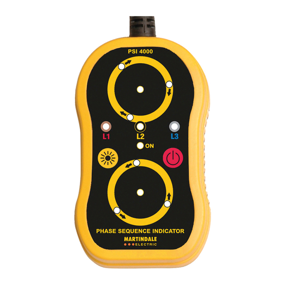
1.2 Description
The PSI4000 and PSI4300 are Non-Contact Phase Detector and
Phase Sequence Indicators with the following features:
N
Non-contact connection clips to enhance user safety during
testing and also allow the testing of insulated conductors.
N
Illuminated LED's to indicate the detection of live phases.
N
Rotating LED's and buzzer tones to indicate clockwise or
anticlockwise phase sequence.
N
Auto-off function after 5 minutes of non-detection.
N
Enhanced brightness switch to make the indication brighter in
strong ambient light.
N
Magnetic studs on rear casing to allow hands free operation.
The PSI4000 indicates correct phase sequence as a clockwise
rotation while the PSI4300 indicates correct phase sequence as an
anti-clockwise rotation.
1.3 Accessories (included)
N
4 x 1.5V batteries LR6/AA
N
Soft case
N
Instructions
1.4 Battery Installation
Refer to section 4.1 (battery replacement) for the battery
installation instructions for the PSI4000 / PSI4300.
1
Advertisement
Table of Contents

Subscribe to Our Youtube Channel
Related Manuals for MARTINDALE PSI4000


Summary of Contents for MARTINDALE PSI4000
- Page 1 If there is any damage then CONTENTS consult your distributor immediately. Introduction 1.2 Description Inspection The PSI4000 and PSI4300 are Non-Contact Phase Detector and Description Phase Sequence Indicators with the following features: Accessories Non-contact connection clips to enhance user safety during Battery Installation testing and also allow the testing of insulated conductors.
- Page 2 This may break or damage the sensor clip wires. 3.4 Enhanced Brightness 3.6 Proving Check Before and after use, prove the function of the PSI4000 / PSI4300 Press the button to increase the brightness of the LED’s when by performing steps 1 to 4 below: using the PSI4000/PSI4300 in strong ambient light.
- Page 3 L1, L2 or L3 LED’s illuminated. or phases live. 2. To determine phase presence and phase sequence, attach the (see Note 1) three sensor clips of the PSI4000 / PSI4300 to the three Respective phase L1, L2 or L3 LED’s OFF. or phases missing.
- Page 4 5. WARRANTY AND LIMITATION OF LIABILITY The instrument should be kept in warm dry conditions away from This Martindale product is warranted to be free from defects in direct sources of heat or sunlight, and in such a manner as to material and workmanship under normal use and service.
Need help?
Do you have a question about the PSI4000 and is the answer not in the manual?
Questions and answers