
Related Manuals for MARTINDALE VR2230


Summary of Contents for MARTINDALE VR2230
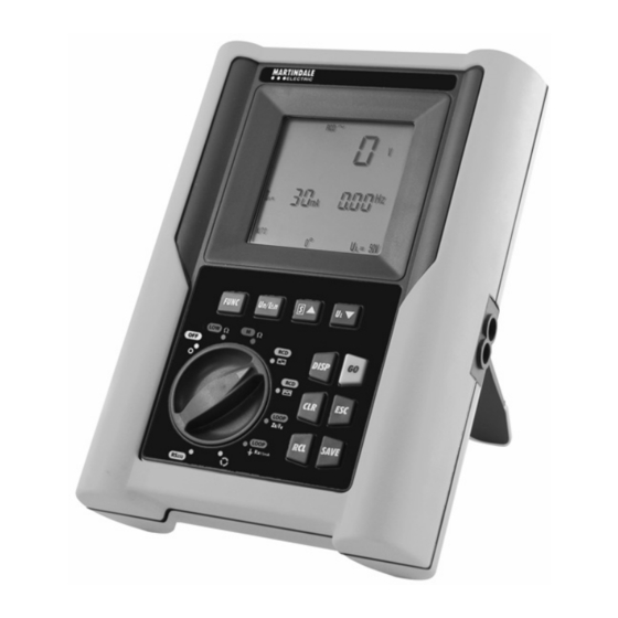
- Page 1 ELECTRICIAN’S TESTER VR2230 INSTALLATION TESTER VR2240 MULTIFUNCTION TEST INSTRUMENTS USER INSTRUCTION MANUAL...
-
Page 2: Table Of Contents
Index: SAFETY PRECAUTIONS AND PROCEDURES..............4 1.1. Preliminary instructions......................4 1.2. During use 1.3. After use ..........................5 GENERAL DESCRIPTION.....................6 2.1. Instrument description ......................8 PREPARATION FOR USE....................10 3.1. Initial quality checks......................10 3.2. Power suppply ........................10 3.3. Battery Replacement ......................10 3.4. Calibration ..........................10 3.5. Storage..........................10 DESCRIPTION OF THE ROTARY SWITCH FUNCTIONS ..........11 4.1. - Page 3 RESETTING THE INSTRUMENT AND DEFAULT PARAMETERS........59 6.1. Reset Procedure........................59 6.2. Default Parameters.......................59 CONNECTION TO A PC (VR2240 ONLY) ................60 PRINTING WITH AN OPTIONAL SERIAL PRINTER (VR2240 ONLY) .......61 ACCESSORIES & MAINTENANCE…….……………………………………..…………………62 TECHNICAL SPECIFICATIONS ..................63 10.1. Technical features ........................63 10.1.1. Safety standards........................65 10.1.2.
-
Page 4: Safety Precautions And Procedures
1. SAFETY PRECAUTIONS AND PROCEDURES This tester conforms with safety standards BSEN61557 and BSEN 61010-1 relating to electronic measuring instruments. WARNING For your own safety as well as that of the apparatus you are recommended to follow the procedures described in this instruction manual and carefully read all the notes preceded by the symbol Adhere strictly to the following instructions before and during measurements: Do not take measurements in wet environments. -
Page 5: During Use
1.2. DURING USE Read carefully the following recommendations and instructions: WARNING Non-compliance with the Warnings and/or Instructions may damage the apparatus and/or its components or seriously injure the operator Before selecting any function disconnect the test leads from the circuit under test. When the instrument is connected to a circuit, do not touch any test lead which is not being used. -
Page 6: General Description
2. GENERAL DESCRIPTION This all-in-one tester incorporates continuity, insulation resistance, RCD, earth loop impedance, phase loop impedances, earth resistance and phase rotation tests. This unit is smaller and more compact than other machines on the market, which makes them very comfortable to use in confined and hazardous areas. The unit can be held comfortably in one hand. - Page 7 Measurement on general and/or selective RCDs A type ( of the following parameters: Tripping time. Tripping current. Contact voltage (U Overall earth resistance (R In this mode the instrument can measure the overall earth resistance without causing RCD’s to trip. LOOP Z Measurement of line and fault loop impedance with calculation of prospective short circuit current.
-
Page 8: Instrument Description
S ▲ ∆n FUNC ▼ START DISP DISPLAY Rotary STOP switch: CLEAR Rotate to select the function SAVE SAVE RECALL VERITEST VR2230 VR2230 S ▲ ∆n ▼ FUNC START DISP DISPLAY Rotary STOP switch: CLEAR Rotate to select the function SAVE... - Page 9 Description of controls Multifunction key to select measuring modes. FUNC Key for selection of differential currents during tests of RCDs or rated ∆n voltages during tests of insulation resistance (depends on the selected measurement) with the rotary switch. Key for selection of RCD type (General or Selective) or to increase the S ▲...
-
Page 10: Preparation For Use
3. PREPARATION FOR USE 3.1. INITIAL QUALITY CHECKS This instrument has been checked mechanically and electrically prior to shipment. Every care has been taken to ensure that the instrument reaches you in perfect condition. In the unlikely event that you have to send the instrument back to us, please follow the instructions detailed in section 11. -
Page 11: Description Of The Rotary Switch Functions
4. DESCRIPTION OF THE ROTARY SWITCH FUNCTIONS 4.1. LOWΩ: CONTINUITY TEST OF EARTH, PROTECTIVE AND EQUALIZING POTENTIAL CONDUCTORS The measurement is performed with a test current higher than 200mA and open circuit voltage ranging from 4 to 24V DC according to BSEN 61557-4 and VDE 0413 part 4. WARNING Before carrying out the continuity test make sure that there is no voltage at the ends of the conductors under test. -
Page 12: Cal" Mode
4.1.1. "CAL" MODE 1. Select CAL mode with the FUNC key. 2. Connect the Red and Black cables to the instrument input terminals P and N respectively: CAT III INPUT MAX 440 V P-N-E 250 V Black Linking of instrument terminals during calibration procedure. 3. - Page 13 LEADS USED FOR THE TEST Before any measurement always make sure that the unit has been calibrated with the test leads in use. During a continuity test, if the resistance value measured is less the calibration offset value stored, the symbol is displayed as well as blinking “CAL”...
-
Page 14: Procedure To Measure Continuity Of Equalising Potential Conductors
4.1.2. Procedure to measure the continuity of conductors "AUTO", "R+", "R-", "R+TIMER" and "R-TIMER" 1. Select the desired mode with the FUNC key. 2. Connect the Red and Black cables to the instrument input terminals P and N respectively. CAT III INPUT MAX 440 V P-N-E... - Page 15 4.1.2.1. "AUTO" Mode Average At the end of the test, if the average Ω CAL LOW resistance value resistance value Ravg is lower than Ravg. 1.07 5Ω the instrument emits a double Ω sound signal indicating the positive outcome of the test and displays a Average test screen similar to this.
-
Page 16: Mode "Auto", "R+", "R-", "R+Timer", "R-Timer" 4.1.3. Other Error Screens "Auto", "R+", "R-", "R+Timer", "R-Timer" Tests
4.1.3. Error screens which may occur during "AUTO", "R+", "R-", "R+TIMER", "R- TIMER" tests If a value of Ravg or R+ or R- higher Ω CAL LOW Only if mode than or equal to 5Ω but lower than Ω 5.75 R+TIMER or R- 99.9Ω... - Page 17 If a voltage higher than 10V is detected Ω CAL LOW WARNING: the at the test leads, the instrument does test was not not carry out the test and displays the performed because of screen alongside for 5 seconds. Then VOL AG excessive voltage the instrument displays the screen for...
-
Page 18: Mω: Insulation Resistance Measurement With The Test Voltage Of 50V, 100V, 250V, 500V Or 1000V
4.2. MΩ: INSULATION RESISTANCE MEASUREMENT WITH TEST VOLTAGE OF 50V*, 100V*, 250V, 500V OR 1000V The measurement is carried out in accordance with BSEN 61557-2 and VDE 0413 part 1. Before carrying out the insulation test make sure that the circuit under test is not energized and all the loads are disconnected. -
Page 19: Procedure To Measure Insulation Resistance In Any Mode
4.2.1. Procedure to measure insulation resistance 1. Select the desired mode using the FUNC key. 2. Connect the Red and Black test leads to the instrument input terminals P and N respectively, Black CAT III INPUT MAX 440 V P-N-E 250 V Example insulation test between phase (#1) and earth in a 3 phase electrical installation using test leads. - Page 20 4.2.1.1. "MAN" Mode Press the GO key. The instrument performs the test lasting for: Minimum 10 seconds if the key is pressed and released within 5 seconds. Or until the key is released. Insulation At the end of the test, if the resistance resistance value value R...
- Page 21 4.2.1.2. "AUTO" Auto Press the GO key. The instrument performs the measurement ending when the measured value stabilizes. Note: Press the GO key again to stop the test At the end of the test, if the resistance Insulation value R detected is lower than R resistance value (see following table) the instrument...
- Page 22 4.2.1.3. "TIMER" Mode 6. When using "TIMER" mode, use the following keys to set the duration time of the test: press this key to increase the duration of the test (Tmax=999 seconds). S ▲ press this key to decrease the duration of the test (Tmin=10 seconds). ▼...
-
Page 23: Special Cases Which May Occur During The Tests "Man", "Auto", "Timer
4.2.2. Other screens which may appear during "MAN", "AUTO" & "TIMER" tests If a value of R higher than R The symbol ">" detected (depending on the selected means that the >999 MΩ voltage, the instrument emits a double resistance value is higher than beep at the end of the test indicating 500 V... -
Page 24: Rcd Rcd
4.3. TESTS ON TYPE A OR AC RCD’S The test is performed according to BSEN 61557-6, BSEN61008, BSEN61009, BSEN60947-2 B 4.2.4 and VDE 0413 part 6. WARNING The automatic check of the RCD causes tripping of the RCD itself. Therefore check that there is no power or load connected downstream which could be affected by the installation switching off. - Page 25 Note: According to standard practice it is recommended to perform RCD tests both with phase at 0° and with phase at 180°. Therefore the test must be repeated for both phase values of test current. If the RCD under test is of a type sensitive to both AC and unidirectional pulsing leakage currents, it is advisable to perform the test both with sine wave and unidirectional pulse current with phase 0°...
- Page 26 Note: On selective RCDs it is possible to carry out the following tests ”Man ½ I ”, ”Man 1 ∆n ”, ”Man 2 I ”, ”Man 5 I ”, “AUTO”. ∆n ∆n ∆n The key U ▼ is used to select one of the following limit values for the ▼...
-
Page 27: Procedure For Rcd Testing
4.3.1. Procedure for RCD testing 1. Select the desired mode (MAN, x1, x2, x5, AUTO, *RAMP) with the FUNC key. 2. Connect the 3 red, black and green connectors of the three-terminal mains cable, or the single test leads, to the corresponding input terminals of the instrument P, N, E (see possible connections in the pictures below). - Page 28 4.3.1.1. "MAN x½" Mode Press the GO key once. The instrument carries out the test injecting a current in phase with positive half wave of the voltage indicated on display by 0°. Press the GO key twice. The instrument carries out the test injecting a current in phase with negative half wave of the voltage indicated on display by 180°.
- Page 29 4.3.1.2. "MAN x1, x2 & x5" Modes Press the GO key once. The instrument carries out the test injecting a current in phase with positive half wave of the voltage indicated on display by 0°. Press the GO key twice. The instrument carries out the test injecting a current in phase with negative half wave of the voltage indicated on display by 180°.
- Page 30 4.3.1.3. "AUTO" Mode Press the GO key: The instrument carries out the following six tests with different values of rated current: 1/2x I at 0° (the RCD should not trip). ∆n 1/2x I at 180° (the RCD should not trip). ∆n at 0°...
- Page 31 4.3.1.4. * "RAMP " Mode (VR2240 ONLY) Press the GO key once. The instrument carries out the test injecting a current in phase with positive half wave of the voltage indicated on display by 0°. Press the GO key once. The instrument carries out the test injecting a current in phase with negative half wave of the voltage indicated on display by 180°.
- Page 32 4.3.1.5. Mode "U " Press the GO key once: the instrument carries out the test. or RCD If the RCD does NOT trip the instrument emits a double sound signal indicating the positive OK: indicates that outcome of the test and displays a the RCD passed screen similar to this.
-
Page 33: Tripping Times For General And Selective Rcds
4.3.2. Tripping times for general and selective RCDs If the parameters set on the instrument are in keeping with the type of RCD under test (and if this works correctly) the test with leakage current I x1, I x2, I x5 SHOULD cause ∆N ∆N... -
Page 34: Other Situations Which May Occur During Rcd Tests In Any Working Mode
4.3.3. Other situations which may occur during RCD tests in any working mode Should the instrument detect that the or RCD phase and/or neutral cables are not connected to an installation, the screen alongside is displayed when pressing VOL AG Message “no VOL tAGE”: too low a voltage was detected or RCD... - Page 35 If the instrument detects that the earth or RCD cable (green) is not connected, the 1999 Ω > screen alongside is displayed for 5 seconds after which time the screen reverts to the initial display. Check the Message “no PE”: the connections of PE conductor under instrument does test.
- Page 36 *During the ramp test, if the RCD or RCD trips to break the circuit at a tripping current higher than I (Type AC) or 1.4 ∆n (Type A with I >10mA) or 2 x I RCD tripping current ∆n ∆n ∆n ≤10mA), the instrument (Type A with I...
- Page 37 Message If the instrument is unable to generate “HI rES”: the the current because the fault loop instrument presents a too high a resistance, the detected a instrument emits a long sound signal excessive Ι at the end of the test and displays a resistance ∆N therefore it is...
-
Page 38: Loop Zs /Ik: Measurement Of Line Impedance E, Fault Loop Impedance And Calculation Of Prospective Short And Fault Circuit Current
4.4. LOOP Z MEASUREMENT OF LINE IMPEDANCE, FAULT LOOP IMPEDANCE AND CALCULATION OF PROSPECTIVE SHORT CIRCUIT AND FAULT CURRENT WARNING This test is designed for use where there is no RCD in the circuit. This test will trip the RCDs. Turn the switch to LOOP Z position. -
Page 39: P-N" Mode
4.4.1. "P-N" Mode 1. Select P-N mode with the FUNC key. 2. If possible disconnect all low impedance loads downstream of the point at which the measurement is to be taken, since such impedances would be in parallel with the line impedance to be measured. - Page 40 Calculation formula for prospective short circuit current: ≤ 150V where U = phase to neutral voltage 127V if V meas ≤ 265V 230V if 150V < V meas SAVE SAVING: *The tests can be stored by pressing the SAVE key twice * VR2240 only...
-
Page 41: P-P" Mode
4.4.2. "P-P" Mode 1. Select P-P mode with the FUNC key. 2. If possible disconnect all low impedance loads downstream of the point at which the measurement is to be taken, since such an impedance would be in parallel with the line impedance to be measured. -
Page 42: P-Pe" Mode
4.4.3. Mode "P-PE" 1. Select P-PE mode with the FUNC key. 2. Connect the three red, black and green connectors of the three-terminal mains test lead or of the single test leads in the corresponding input terminals of the instrument P, N, E (see possible connections in the following pictures). - Page 43 Press the GO key once. The instrument carries out the test injecting a current in phase with positive half wave of the voltage indicated on display by 0°. Press the GO key twice. The instrument carries out the test injecting a current in phase with negative half wave of the voltage indicated on display by 180°.
-
Page 44: Other Situations Which May Occur During Loop, Zs/Ik Tests In Any Working Mode
4.4.4. Other situations which may occur during LOOP, Z tests in any working mode Should the instrument detect that the LOOP Message phase and/or neutral cables are not "no VOL tAG”: connected to an installation, the screen too low a voltage alongside is displayed when pressing was detected. - Page 45 If the instrument detects that the earth LOOP Message cable (green) is not connected, the “no PE”: the 1999 Ω > screen alongside is displayed for 5 instrument does not detect the seconds then the screen reverts to the protection initial display.
- Page 46 if the instrument detects a resistance Message "Err": LOOP the instrument lower than 0,03Ω, the screen alongside detects a line is displayed. Line impedance value is loop resistance too low and the instrument doesn’t lower than 0.03Ω. perform the measurement THE PREVIOUS RESULT CANNOT BE SAVED.
-
Page 47: Measurement Of Earth Resistance With A15Ma Current And Calculation Of Prospective Fault Current (Pfc)
4.5. : MEASUREMENT OF EARTH RESISTANCE WITH 15mA CURRENT a15mA AND CALCULATION OF PROSPECTIVE FAULT CURRENT (PFC) WARNING This test is designed for circuits where there is an RCD. Provided pre-existing levels of earth leakage are low this test will not trip RCDs. The test results are presented to 1Ω... - Page 48 The U ▼ key is used to select one of the following limit values for ▼ the contact voltage (which can be shown in rotation when pressing the key): 50V (default) 25V. Signifies non- trip Press the GO key. The instrument starts the test. low current loop test At the end of the test the instrument...
-
Page 49: Other Situations Which May Occur During R A15Ma Tests
4.5.1. Other situations which may occur during R tests A15mA Should the instrument detect that the Message “No RCD LOOP VOLTAGE”: phase and/or neutral cables are not Too low a voltage connected to an installation, a screen was detected. similar to this is displayed when pressing GO. - Page 50 If the instrument detects that the earth Message RCD LOOP cable (green) is not connected, the "no PE": the 1999 Ω > instrument does screen alongside is displayed for 5 not detect the seconds then the screen reverts to the protection circuit.
- Page 51 If, when using the P-PE mode the RCD LOOP Message ">1999": instrument caries out the test and The instrument 1999 Ω > detects an earth resistance higher detects an earth resistance higher than 1999Ω, a screen similar to this is P-PE than 1999Ω.
-
Page 52: Phase Sequence Rotation
4.6. PHASE SEQUENCE Turn the switch to the position. 4.6.1. Procedure for PHASE SEQUENCE testing 1. Connect the three red, black and green connectors of the single test leads to the corresponding input terminals of the instrument P, N, E (see possible connections in the following picture). When testing at loose cables or busbars, connect the crocodile clips to the free ends of these. - Page 53 FUNC Press the FUNC key to display the three delta voltages L1-2, L2-3, L3-1 in turn. The instrument will display a screen similar to this: Voltage value between Phase1 and Phase2 sampled when the FUNC key is pressed. "L12": indicates that the value reported is the voltage measured between Phase1 and Phase2.
-
Page 54: Other Situations Which May Occur During Phase Sequence Tests
4.6.2. Other situations which may occur during phase sequence tests if the voltage between each phase is lower than 100V, the instrument does not perform the test and displays a screen similar to this. VOL AG Message “Lo VOL tAG”: the instrument detects low voltage between at least 2 phases. -
Page 55: How To Save, Recall And Clear Data Stored In Memory (Vr2240 Only)
5. *HOW TO SAVE, RECALL AND CLEAR DATA STORED IN MEMORY (VR2240 ONLY) 5.1. SAVE: "SAVE" KEY To store the result of any test carried out, proceed as follows: Press the SAVE key once. SAVE If the memory of the instrument LOOP contains previously stored test results, a screen similar to this is displayed. -
Page 56: Recall: "Rcl" Key
5.2. *RECALL: "RCL" KEY (VR2240 ONLY) If you want to recall the stored test results proceed as follows: Press the RCL key. If the memory of the instrument contains previously stored test results, a screen similar to this is displayed. The memory location in which the measurement result was stored to. -
Page 57: Clear: "Clr" Key
5.3. *CLEAR: "CLR" KEY (VR2240 ONLY) If you want to delete the stored tests results, proceed as follows: Press the RCL key. The instrument displays a screen similar to this: The memory location in which the measurement results are stored in. Value of the parameter P related to the measurement saved. - Page 58 Press the ESC key to leave the memory menu and go back to the selected measurement. Example: 97 tests have been stored in the instrument. If you want to delete the tests from 43 to 97, proceed as follows: Press RCL. Use the keys U ▼, S▲...
-
Page 59: Resetting The Instrument And Default Parameters
6. *RESETTING THE INSTRUMENT AND DEFAULT PARAMETERS (VR2240 ONLY) 6.1. RESET PROCEDURE 1. Press the keys DISP, CLR, RCL at the same time and and turn the rotary switch to any test function. The screen shown here is displayed for approximately 5 seconds, during which the instrument emits a sound signal and then displays the screen relative... -
Page 60: Connection To A Pc (Vr2240 Only)
To transfer the stored data from the VR2240 to the PC, follow the directions below. 1. Turn the rotary switch to the RS232 position (In the case of the VR2230, this position is marked “CAL” and is only used at the point of manufacture and is of no use to the end user of the instrument.) -
Page 61: Printing With An Optional Serial Printer (Vr2240 Only)
To transfer the stored data from the VR2240 to the printer, follow the directions below. 1. Turn the rotary switch to the RS232 position. (In the case of the VR2230, this position is marked “CAL” and is only used at the point of manufacture and is of no use to the end user of the instrument.) -
Page 62: Accessories & Maintenance
Calibration The recommended calibration interval is 12 months. Martindale Electric will carry out routine calibration (on a chargeable basis) if the instrument is returned, carriage paid, to the address on the final page of this document. Alternatively, a chargeable collection and return service is available. Please call our calibration and service department on 01923 650620 for further details. -
Page 63: Technical Specifications
TECHNICAL SPECIFICATIONS 10.1. TECHNICAL FEATURES Accuracy is indicated as [% of reading + number of digits]. It refers to the atmospheric conditions listed in paragraph 10.2.1. Continuity (Low Ω Test mode Accuracy Measuring range (Ω) Resolution (Ω) 0.01 - 19.99 0.01 AUTO, R+, R- ±(2% rdg + 2 dgt) - Page 64 Tripping time (t ∆N Measuring range (ms) Resolution (ms) Accuracy ½ I 0 - 999 ∆N ∆N 0 - 200 general ∆N 0 - 250 selective ±(2% rdg + 2 dgt) 0 - 50 general ∆N 0 - 160 selective NB.
-
Page 65: Safety Standards
Phase-Earth Loop Impedance (LOOP Z Accuracy Measuring range (Ω) Resolution (Ω) 0.03 - 19.99 0.01 20.0 - 199.9 ±(5% rdg + 2 dgt) 200 - 1999 Max peak test current 100V 3.17A test duration: 80ms 230V 6.64A test duration: 40ms ±10% I Accuracy current measurement max Pk... -
Page 66: Environment
10.2. ENVIRONMENT 10.2.1. Environmental working conditions Reference temperature: 23° ± 5°C Working temperature: -10°C – 50 °C Relative humidity allowed: <80% Storage temperature: -20 – 60 °C Storage humidity: <80% 10.2.2. EMC This instrument was designed in compliance with the EMC standards in force and compatibility have been tested for EN61326-1 (1997) + A1 (1998) This instrument complies with the requirements of the European Low Voltage Directive 72/23/CEE (LVD) and EMC 89/336/CEE, amended with 93/68/CEE. -
Page 67: Service
SERVICE Repair & Service There are no user serviceable parts in this unit. Return to Martindale Electric Company Ltd if faulty, unless fuse replacement only is necessary. Our service department will promptly quote to repair any faults that occur outside the warranty period. Please call our service and... - Page 68 Martindale Electric Company Limited Martindale Electric Co Ltd, Metrohm House, Imperial Park, Imperial Way, Watford, Hertfordshire, WD24 4PP, UK Tel:+44(0)1923 441717 Fax:+44(0)1923 446900 E-mail:sales@martindale-electric.co.uk Website: www.martindale-electric.co.uk © Martindale Electric Company Ltd. 2006 LIT22302240 Rev 9 Registered in England No. 3387451...
Need help?
Do you have a question about the VR2230 and is the answer not in the manual?
Questions and answers