Table of Contents
Advertisement
Quick Links
Advertisement
Table of Contents

Related Manuals for MachMotion Apollo III


Summary of Contents for MachMotion Apollo III
- Page 1 Apollo III MANUAL – MACH3 Specializing in CNC Automation and Motion Control...
- Page 2 P a g e R0124 11/10/14 This manual covers the setup and configuration of the Apollo III motion controller connected to the control using Mach3. Formatting Overview: • Menus, options, icons, fields, and text boxes on the screen will be bold (e.g. the Help icon).
-
Page 3: Table Of Contents
Slaving an Axis ........................20 SPINDLE SETUP ......................21 Wiring a Spindle ........................ 21 3.1.1 VFD from MachMotion ......................21 3.1.2 VFD Other Than from MachMotion ................... 22 3.1.3 No VFD ........................... 22 Spindle Configuration ......................23 3.2.1 Spindle Pulley Setup ......................23 Turning on the Spindle ....................... - Page 4 8.1.1 Direct Connection ........................40 8.1.2 Router Connection ......................... 42 Apollo III Software Installation ..................42 8.2.1 Installing Apollo III Plugin and Firmware ................. 42 8.2.2 Installing VSI Manager ......................42 Mach3 Integration ......................44 8.3.1 Mach3 Startup ........................44 Apollo III Status Window ....................
- Page 5 Default Motor Outputs...................... 80 15.1.2 Default Input Signals ......................80 15.1.3 Default Output Signals ..................... 81 15.2 Apollo III Drawing ......................83 15.3 Apollo III Case Mount Drawing ..................85 WARRANTY INFORMATION ..................87 16.1 Additional Resources ....................... 87 Apollo III Using Mach3...
- Page 6 P a g e **This page intentionally left blank** Apollo III Using Mach3...
- Page 7 P a g e Part 1: INSTALLATION & SETUP Apollo III Using Mach3...
-
Page 8: Part 1: Introduction
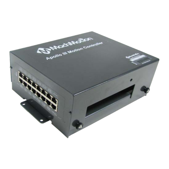
1 PART 1: INTRODUCTION 1.1 Overview The Apollo III is MachMotion's Ethernet motion controller. It uses differential or single-ended step and direction to control up to 6 axes with full encoder feedback (full closed loop). It also has 16 inputs, 8 outputs, excellent position resolution, two MPG inputs, and spindle encoder feedback 1.2 Tool Required... - Page 9 P a g e FIGURE 1 APOLLO III OVERVIEW WARNING DO NOT connect 115VAC to any part of the Apollo III motion controller. It could cause serious damage to the controller. Apollo III Using Mach3...
-
Page 10: Status Leds
P a g e 1.4 Status LEDs The Apollo III has four status LEDs that show the status of the controller’s processor. The LEDs are located close to the center of the controller. See the figure below. Figure 2 Status LEDs... -
Page 11: Specifications
P a g e | 11 1.5 Specifications Below are the specifications for the Apollo III motion controller. Item Specification Input Power 24VDC Max Power Consumption Axes Step and Direction Axis Control 5V Single Ended and Differential Connection RJ45 Connectors and Terminal Blocks Max Pulse Speed 1.6 MHz... -
Page 12: Drawing
Scale drawing of the Apollo III and mounting case are located in Appendices, pages 83 and 85. Hardware Star tup To power the Apollo III, you must supply 24VDC to the power connection located at the top right of the board as shown below. The top orange LED labeled Power will turn on. -
Page 13: Software Startup
Mach3 Loader shortcut opens the following window: FIGURE 6 LOADER After double clicking on a profile or opening a profile from Mach3 Loader, a window will come up asking for agreement with the Mach3 Legal Notice. FIGURE 7 LEGAL NOTICE Apollo III Using Mach3... -
Page 14: Axis Setup
2 AXIS SETUP 2.1 Apollo lll Cover Removal All of the drives and external I/O will be wired into the Apollo III. Begin by removing the cover by loosening the four black knobs on the sides. FIGURE 8 APOLLO III COVER REMOVED Note: For more information about the Apollo III see the Apollo III User’s Manual. -
Page 15: Enabling Axes
FIGURE 9 DIFFERENTIAL STEP AND DIRECTION, AND ENCODER FEEDBACK RJ45 CONNECTIONS 2.2 Enabling Axes After the drives are connected to the Apollo III, open up Mach3, and enable the axes as follows: Note: This may already be setup depending on your system. -
Page 16: Axis Calibration
Complete the following procedure to do the manual calibration: Note: If the MachMotion plugin is not listed under PlugIn Control, see the Axis Configuration Worksheet to do the calculations by hand or use the calibration wizard on page 18. The worksheet can be found on the MachMotion website under software setup documentation. - Page 17 Mitsubishi Yaskawa Stepper TABLE 2 – DEFAULT DRIVE RATIO VALUES FIGURE 12 - MACHMOTION PLUGIN CALIBRATION CALCULATOR 5. Choose the machine configuration for the axis from the following three options. a. Ball Screw i. Enter the ball screw pitch ii. Enter the gearing ratio between the shaft and the motor...
-
Page 18: Calibration Wizard
FIGURE 13 MOTOR TUNING AND SETUP In the column titled Axis Selection, press the button corresponding to the axis you want to set up. The selected axis’s parameters will be loaded. Now you can adjust your velocity setting as shown below. Apollo III Using Mach3... -
Page 19: Backlash Calculation
2.4 Backlash Calculation The Apollo III has backlash compensation. Use the MDI line to enter G-Code to move the axes. To calculate the machine’s backlash, follow the steps below. 1. Move an axis in one direction farther than the maximum possible backlash. -
Page 20: Reversing Direction
20 | P a g e Backlash (mm, inch) – This field defines the backlash distance in inches or mm. The Apollo III uses this value to calculate virtual load position. Backlash Speed % – This field adjusts the maximum acceleration that the backlash counts can be applied. The Apollo III takes the max acceleration from the motor tuning and multiplies it by this percentage. -
Page 21: Spindle Setup
3.1 Wiring a Spindle 3.1.1 VFD from MachMotion The process for setting up a VFD from MachMotion is extremely simple. Simply plug the control cable into the Spindle Control RJ45 jack located on the bottom row of the large RJ45 block. -
Page 22: Vfd Other Than From Machmotion
P a g e FIGURE 20 SPINDLE CONTROL RJ45 JACK 3.1.2 VFD Other Than from MachMotion Any VFD can be wired into the Spindle Control RJ45 jack by cutting the end off of a CAT5 cable and wiring the loose ends to the VFD according the following pin out. -
Page 23: Spindle Configuration
10V). A medium speed pulley could go from 300 to 1200 RPM and high speed pulley could run from 1200 to 2400 RMP. To change the pulleys, go to Config->Spindle Pulleys. The Pulley Selection window will appear as shown in Figure 22. Apollo III Using Mach3... -
Page 24: Turning On The Spindle
If the spindle is not running correctly at this point some settings may need to change inside the VFD. In this situation reference the VFD manufacturer manual. Note: See the Mitsubishi VFD Installation Guide for setup information if it was purchased from MachMotion. 3.4 Reversing Direction To reverse a pulley’s direction, go to Config->Spindle Pulleys. -
Page 25: Limits And Homing Setup
4 LIMITS AND HOMING SETUP The Apollo III motion controller has up to 16 inputs that can be used for the limit and home switches. To maximize the number of inputs available for other functions, wire multiple switches in series as shown below. -
Page 26: Homing Setup
Make sure to keep a hand on the Emergency Stop button the first time the machine homes............................2. Open to the menu bar and click Config->Homing/Limits. The Motor Home/Soft Limits window will come up as shown below. Apollo III Using Mach3... -
Page 27: Soft Limits Setup
Note: If the value is positive, place it into the Soft Max limit and set the Soft Min limit to zero. Otherwise, with a negative value, set the Soft Max to zero and the Soft Min to the recorded value. 5. Press [OK]. Apollo III Using Mach3... -
Page 28: Input Setup
5.1 Generic Inputs All 16 inputs on the Apollo III can be used for limit switches, home switches, tool changers, or anything else. To learn how to set up limit switches, go to Setting up Limits and Homing on page 24. As shown below, the inputs are located on the main green terminal block. -
Page 29: Wiring Inputs
The inputs run from X0, up to X15. If the LED is on, then the input is activated. Different configurations can be selected for each input by using the jumpers near the bottom right of Apollo III. Each jumper corresponds to an input. -
Page 30: Sinking Inputs (Npn)
Use a 3.9k ohm resistor and connect it between XSL and C0+. Below is an example of a 24V NPN proxy with an internal pull-up resistor. The jumper on the Apollo III must be completely removed for this to work. -
Page 31: Sourcing Inputs (Pnp)
1. On the menu bar click on Config->Ports and Pins. 2. Select the Input Signals tab. Scroll down to the desired input. There are 4 inputs and 15 OEM triggers. An OEM trigger acts exactly like an input. Apollo III Using Mach3... -
Page 32: Output Setup
The input is now be set up. 6 OUTPUT SETUP 6.1 Generic Outputs The Apollo III has 8 logic outputs that can be used for any low current application. They are located on the small green terminal block as shown below. Apollo III Using Mach3... -
Page 33: Wiring Outputs
There are two separate commons for the outputs. The common C1+ is for outputs Y0-Y3 and C2+ is for Y4-Y7. Each common can take 7-48VDC. If the outputs being used are using the voltage supply from Apollo III, each output can only supply 125mA. However, if they are supplied using a separate voltage source, each output can source up to 250mA. -
Page 34: Configuring Outputs
6. Set the Active Low column to a green check for a normally closed signal or red x for normally open. 6.4 Using Outputs Outputs 5-10 can be controlled with M-Codes. One M-Code turns an output on, and the other M-Code turns the output off. Use the table below for a reference. Apollo III Using Mach3... -
Page 35: Mist And Flood Control
TABLE 7 MIST AND FLOOD CONTROL 7 ADVANCED OPTIONS A number of advanced features can be accessed and configured in the MachMotion plugin such as periodic oiler control and custom user messages. Begin by going to PlugIn Control->MachMotion Config to open the MachMotion plugin. - Page 36 P a g e Output FIGURE 40 - MACHMOTION PLUGIN, IO CONFIGURATION In general, only change values and settings in the red boxes shown above. The rest of the options are used to set up the control at the factory. Please do not change these settings.
- Page 37 Now whenever Input4 is active, E-Stop will be flagged. User FIGURE 43 - MACHMOTION PLUGIN, USER DEFINED MESSAGES The User Messages can be configured to have custom messages displayed. Each input will do a specific function (E-Stop, feed hold, stop) and write to the status bar except the No Action option. The No Action just displays the message on the status bar whenever the input is active.
- Page 38 38 | P a g e **This page intentionally left blank** Apollo III Using Mach3...
- Page 39 P a g e | 39 Part 2: ADVANDED SETUP Apollo III Using Mach3...
-
Page 40: Part 2: Advanced Setup
The Apollo III can be connected directly to the control or via an Ethernet router. Either of the two Ethernet ports on the Apollo III can be used. The Ethernet ports have a built in Ethernet switch so you can also use them to daisy chain other Ethernet devices together on a local network. - Page 41 3. In the top left corner of the Network and Sharing Center window click on Change adapter settings. 4. Right click on the network port that the Apollo III is connected to and select Properties. 5. From the list below double click on Internet Protocol Version 4.
-
Page 42: Router Connection
42 | P a g e 8.1.2 Router Connection When using a network router to connect the Apollo III to the control there is no special network setup required. The router will take care of the IP assignments. Apollo III... - Page 43 The firmware should now be updated. WARNING Install the plugin AND download the firmware to the Apollo III. If the firmware and plugin versions do not match, it could cause serious damage to the machine or cause the Apollo III not to operate at all.
-
Page 44: Mach3 Integration
Apollo III. 8.4 Apollo III Status Window To view the status of the Apollo III from inside Mach3, click on PlugIn Control on the top menu bar and then select HiCON Status. -
Page 45: Apollo Iii Configuration
The P stands for the port number. So output Y0 is port 11 pin 0 located at P11 column 0. Note: The HiCON Status window is a great place to check for encoder feedback. 8.5 Apollo III Configuration To change anything inside the controller, the HiCON plugin must be used. Click Config on the main menu bar, then Config PlugIns. - Page 46 5. Axis A(3) 6. Axis B(4) 7. Axis C(5) Each axis tab besides the System tab represents an axis to be controlled through the Apollo III. By default, the System tab will be selected as shown below. Apollo III Using Mach3...
- Page 47 Mach3 profile (e.g. Mach3Mill, Mach3Turn, etc). To exit the plugin, press [OK] and then [OK] again on the PlugIn Control and Activation window. Now, with a brief overview of the Apollo III, it is time to start configuring the controller. Apollo III Using Mach3...
-
Page 48: Enable Circuit
9 ENABLE CIRCUIT The Apollo III has a hardware enable and a drive enable circuit. However, before they will work, the emergency stop circuit must be set up. Use the table below as a quick reference for the different signals. -
Page 49: Hardware Enable
9.2 Hardware Enable The hardware enable is the main enable circuit. It enables all the components on the Apollo III, turns on the 5V enable (5EN) and the 24V enable signals (24EN), and activates the hardware enable relay (HEN). When the hardware enable is set up correctly, it will only activate when there are no emergency conditions. - Page 50 The green LED (labeled Enable) turns on as soon as the controller detects the enable signal from Mach3. The LED does not mean that the hardware enable circuit is activated. The hardware enable circuit is only activated when the red (E-Stop), orange (Power), and green (Enable) LEDs are on. Apollo III Using Mach3...
-
Page 51: Drive Enable
EXT can be jumpered to 5V, 24V, GND, or any other DC voltage up to 48V for different enable signals depending on what the servo drives require. Again, remember that the emergency stop terminals must be connected for anything to enable. Apollo III Using Mach3... - Page 52 P a g e FIGURE 62 DRIVE ENABLE SIGNALS The Mitsubishi, Yaskawa, and TECO servo drives from MachMotion are all enabled with a ground signal. Therefore EXT and GND are connected together as shown below. 0-10 CCW CW GND GND...
-
Page 53: Axes
Now with the enable circuits set up, the next step is to set up the machine axes. 10 AXES To set up the axes, the drives must be connected to the controller, the Apollo III controller must be configured, and the Mach3 software must be set up as defined below. -
Page 54: Single-Ended Control
Brown TABLE 11 AXIS CONTROL RJ45 JACK PINOUTS Any drive from MachMotion can be plugged directly into the axis control RJ45 jacks. 10.1.2 Single-Ended Control To use single-ended control use the terminals on TB1 (the large green terminal block). The top row is for the direction signals and the middle row is for the step signals. -
Page 55: Encoder Feedback
The encoder feedback inputs are located on the top of RJ1. The encoder signal for each axis is directly above the control signal. See the diagram below. Axis Axis Axis Axis Axis Axis FIGURE 67 ENCODER FEEDBACK RJ45 JACKS Apollo III Using Mach3... -
Page 56: Configuring Axes
FIGURE 68 X AXIS CONFIGURATION The control parameters are used to configure the axes. If the Apollo III came with a MachMotion control all of the following parameters will already be set up. For all other systems, the only parameter that should have to change is the Feedback. -
Page 57: Control Parameters
Encoder: Use one of the differential hardware encoder inputs 0…7 as the feedback. None: Use this if the system is not going to use encoder feedback. Homing Type – Defines the homing sequence for each axis. Two types of homing sequences are supported: Apollo III Using Mach3... -
Page 58: Testing Motion
5. Press the button DRIVE ON to turn on the LED beneath the button. This enables the drives. When the LED is green, the drives are enabled. Note: To download a new configuration to the Apollo III, DRIVE ON must be disabled. 6. Press EXECUTE to command the movement The axis can also be homed by pressing the HOME button. -
Page 59: Test Motion Parameters
The Ready LED shows if the Apollo III is ready to accept a motion command. If the Ready LED is green, it implies that the controller is ready to accept new motion commands. -
Page 60: Backlash Compensation
FIGURE 71 BACKLASH COMPENSATION Backlash (mm,inch) – This field defines the backlash distance in inches or mm. The Apollo III uses this value to calculate virtual load position. Backlash Speed % – This field adjusts the maximum acceleration that the backlash counts can be applied. The Apollo III takes the max acceleration from the motor tuning and multiplies it by this percentage. -
Page 61: Slaving An Axis
10.6 Slaving an Axis To configure an axis as a slave, follow the steps outlined below. 4. Click Config->Slave Axis on the main menu bar. It will display the Slave Axis Selection window FIGURE 74 SLAVE AXIS SELECTION WINDOW Apollo III Using Mach3... -
Page 62: Spindle
Note: Make sure to press the [Save Configuration] button after making any setting changes in the HiCON plugin. 11 SPINDLE This section goes through the wiring and configuration process for spindle integration with Mach3. The Apollo III spindle control consists of a 0-10V analog signal for spindle speed and two relays (CW and CCW) for spindle direction. -
Page 63: Wiring A Spindle
TABLE 14 SPINDLE CONTROL RJ45 JACK 11.1.2 VFD from MachMotion The process for setting up a VFD from MachMotion is extremely simple. Simply plug the control cable into the Spindle Control RJ45 jack located on the bottom row of the large RJ45 jack block. -
Page 64: Spindle Feedback
Reversing Switch Kit D0037 FIGURE 79 SPINDLE 11.1.4 Spindle Feedback The Apollo III takes a 5V encoder signal as spindle feedback. Connect it into the top row of RJ1 as shown below. FIGURE 80 SPINDLE FEEDBACK RJ45 JACK Apollo III Using Mach3... -
Page 65: Configuring The Spindle
4. Enable outputs 1 and 2 and set them up to port 14 pin 6 and port 14 pin 7 respectively as shown below. Make sure that the Active Low column is set to a red “X” for both outputs. Apollo III Using Mach3... - Page 66 5. Finally, click on the Spindle Setup tab. Description Setting Disable Spindle Relays Unchecked Clockwise (M3) Output # CCW (M4) Output # Use Spindle Motor Checked PWM Control Checked Step/Dir Motor Unchecked PWM Base Freq. Minimum PWM TABLE 16 SPINDLE SETTINGS Apollo III Using Mach3...
-
Page 67: Spindle Pulley Setup
Use the drop down menu titled Current Pulley to select the pulley to be updated. Enter in the maximum and minimum speeds for each pulley. Then select the current pulley and press OK. Note: Only set up multiple pulleys if the machine has different gears. Apollo III Using Mach3... -
Page 68: Analog Calibration
To use a servo axis as a spindle the HiCON plugin will need to be configured as follows: FIGURE 87 SERVO SPINDLE SETTINGS Set the Spindle Axis drop down to the axis the servo spindle is connected to and set the Spindle Type to Gcode Axis. Apollo III Using Mach3... -
Page 69: Turning On The Spindle
Counter/Clockwise Stop TABLE 17 SPINDLE M-CODES MPGS The Apollo III has two 5V MPG encoder inputs. They are located on RJ1 as shown below. MPG #2 MPG #1 FIGURE 88 MPG RJ45 JACKS Below is the pinout for the MPGs:... - Page 70 70 | P a g e Apollo III Using Mach3...
-
Page 71: Inputs
The MPG is now set up. 13 INPUTS The Apollo III has 16 configurable inputs. These inputs can be used for limit switches, home switches, tool changers, or anything else. As shown below, the inputs are located on the main green terminal block, TB1. -
Page 72: Wiring Inputs
The inputs start counting from X0 and up to X15. If the LED is on, then the input is activated. Different configurations can be selected for each input by using the jumpers near the bottom right of Apollo III. The jumpers start counting from the left at X0 and increment up to X15. -
Page 73: High Voltage Sourcing Inputs (Pnp)
For 9-48V inputs, supply the positive voltage to the C0+ terminal and connect ground to C0-. Set the jumper for the input to the bottom two terminals. Then connect the signal into the corresponding input. For example, the Apollo III shown below is set up for 30V. Notice that input X4 is connected to a switch. 48V Supply... -
Page 74: Low Voltage Sourcing Inputs (Pnp)
Use a 3.9k ohm resistor and connect it between XSL and C0+. Below is an example of a 24V NPN proxy with an internal pull-up resistor. The jumper on the Apollo III must be completely removed for this to work. -
Page 75: Isolated Inputs
6. On the menu bar click on Config->Ports and Pins. 7. Select the Input Signals tab. Scroll down to the desired input. There are 4 inputs and 15 OEM triggers. An OEM trigger acts exactly like an input. Apollo III Using Mach3... -
Page 76: Outputs
The input is now be set up. 14 OUTPUTS The Apollo III has 8 logic outputs that can be used for any low DC current application. They are located on the small green terminal block as shown below. Apollo III Using Mach3... -
Page 77: Wiring Outputs
There are two separate commons for the outputs. The common C1+ is for outputs Y0-Y3 and C2+ is for Y4-Y7. Each common can take 7-48VDC. If the outputs being used are using the voltage supply from Apollo III, each output can only supply 125mA. However, if they are supplied using a separate voltage source, each output can source up to 250mA. -
Page 78: Configuring Outputs
To configure an output, follow the procedure below. 7. On the menu bar click on Config->Ports and Pins. 8. Select the Output Signals tab. Scroll down to the desired output (There are 20 outputs that can be used). FIGURE 106 OUTPUT CONFIGURATION Apollo III Using Mach3... -
Page 79: Using Outputs
Output 7 on M205 Output 7 off M206 Output 8 on M207 Output 8 off M208 Output 9 on M209 Output 9 off M210 Output 10 on M211 Output 10 off TABLE 19 M-CODES FOR OUTPUTS Apollo III Using Mach3... -
Page 80: Appendices
*These will be enabled if drives and motors for these axes were purchased with the control. 15.1.2 Default Input Signals Signal Enabled Port # Pin Number Active Low Emulated HotKey X Home Y Home Z Home A Home B Home Apollo III Using Mach3... -
Page 81: Default Output Signals
Output #1 Output #2 Output #3 Output #4 Output #5 Output #6 Output #7 Output #8 Output #9 Output #10 Table 22 – Default Outputs Apollo III Using Mach3... - Page 82 82 | P a g e **This page intentionally left blank** Apollo III Using Mach3...
-
Page 83: Apollo Iii Drawing
83 | P a g e 15.2 Apollo III Drawing... - Page 84 84 | P a g e **This page intentionally left blank**...
-
Page 85: Apollo Iii Case Mount Drawing
85 | P a g e 15.3 Apollo III Case Mount Drawing... - Page 86 86 | P a g e **This page intentionally left blank**...
-
Page 87: Warranty Information
For warranty service the customer must contact MachMotion for an RMA number and then return the defective product to MachMotion. If a product is sent to MachMotion without an RMA number, the product may be misdirected or delayed. When a product or part is exchanged, any replacement item becomes the customer’s property and the replaced item becomes...
Need help?
Do you have a question about the Apollo III and is the answer not in the manual?
Questions and answers