
Related Manuals for MachMotion Apollo III 1000 Series


Summary of Contents for MachMotion Apollo III 1000 Series
- Page 1 Apollo III - 1000 Series http://www.machmotion.com 14518 County Road 7240, Newburg, MO 65550 (573) 368-7399 • Fax (573) 341-2672...
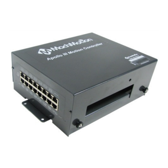
- Page 3 1.1 Overview The Apollo III is MachMotion's Ethernet motion controller. It uses differential or single-ended step and direction to control up to 6 axes with full encoder feedback (full closed loop). It also has 16 inputs, 8 outputs, excellent position resolution, two MPG inputs, and spindle encoder feedback.
-
Page 4: Specifications
Figure 2 Status LEDs Color Label Function Green Power is supplied to Apollo III Orange CTRL Apollo III has an enable signal from control Apollo III has an error Apollo III CPU is running (should be flashing Green when power is supplied) Table 1 - Apollo III Status LEDs 1.5 Specifications Below are the specifications for the Apollo III motion controller. -
Page 5: Hardware Startup
Isolated Optional Enable Circuit Hardware Enable Relay Contacts, 5V Enable, 24V Enable Drive Enable Relay Contacts Emergency Stop Circuit Normally Closed Connection Ethernet Port 10/100 MHz Dimensions 8.32"(L) X 5.75"(W) X 2"(H) Optimal Temperature Range 32° to 100°F (0° to 38°C) Table 2 –... - Page 6 Figure 4 24V Power Connector Software Startup On the desktop of your control, there is a Mach4 shortcut for your machine type. Below is an example of the Mach4 shortcut. Figure 5 Profiles There is also a shortcut for Mach4 Loader. This allows any of the profiles to be loaded from one location. Double clicking on the Mach4 Loader shortcut opens the following window: Figure 6 Loader After double clicking on a profile or opening a profile from Mach4 Loader, a window will come up (Figure 7) asking to...
-
Page 7: Axis Setup
On subsequent startups, once motion and limit switches are set, press [Cycle Start] and the control will enable and home all axes. This prompt can be turned off in the machmotion plugin if desired. 2 Axis Setup Apollo lll Cover Removal All of the drives and external I/O will be wired into the Apollo III. - Page 8 Note, if menu options are greyed out (not active/selectable), click the button to disable the system 2. Enable all the motors that are to be controlled by setting the respective boxes in the right pane to checks. In the example below, motors 0, 1, and 2 are enabled. Figure 10 motor Setup 3.
- Page 9 This is often only needed for high precision machining and typically requires the use of laser for determine very accurate positions. Contact MachMotion for information on setting this up. 2. Select the drive type of the axis being configured.
- Page 10 Enter the ball screw pitch Enter the ball screw pulley # teeth and motor pulley # teeth Note: If the system has a pulley ratio and a gear box use this equation to get the total gear ratio: [Gear Box Ratio] x [Pulley Ratio] = [Total Gear Ratio] Ex: [10:1 Gear Box] x [30 Motor Pulley Teeth/15 Ball Screw Pulley Teeth] = [10] x [30/15] = [20 Total Gear Ratio](20 Motor Pulley Teeth, 1 Ball Screw Pulley Teeth) Enter pinion diameter...
- Page 11 If you want to adjust your velocity, select Configure on the top menu bar, then Control. Select the Motors tab as shown below. Figure 15 Motor Setup In the right pane, click on the motor you want to set up (Click the word to highlight and select the axis). The checkbox is for enabling/disabling the motor).
- Page 12 Figure 16 Backlash Settings WARNING Do not leave the backlash speed zero if you enter in a backlash distance. The Apollo III will not function. For best performance, backlash should be less than .0015 inches. Reversing Direction If a motor moves the wrong direction, it can be reversed in the software. 1.
-
Page 13: Spindle Setup
3.1.1 VFD from MachMotion The process for setting up a VFD from MachMotion is extremely simple. Simply plug the control cable into the Spindle Control RJ45 jack located on the bottom row of the large RJ45 block. Figure 20 Spindle Control RJ45 Jack 3.1.2... - Page 14 If the system does not use a VFD to control the spindle, a FWD/REV Contactor circuit can be used and is available from MachMotion. Wire the spindle according to the diagram below. Notice that 24V is wired to the CW and CCW relay contacts on the top row of the green terminals (the terminals on your Apollo board will likely be black, not green).
-
Page 15: Limits And Homing Setup
4. If the above is correct and still having accuracy issues there are some adjustments in the HiCON plugin that can be made, or there could be some settings/parameters that are not set correctly in the VFD. Contact MachMotion support for further assistance. 4 Limits and Homing Setup 4.1 General Info... - Page 16 4.2 Wiring Switches The Apollo III motion controller has up to 16 inputs that can be used for the limit and home switches. To maximize the number of inputs available for other functions, wire multiple switches for the same axis in series as shown below. Figure 23 Limit Switches in Series Note: For the highest level of safety, wire the limit switches Normally Closed.
- Page 17 Figure 24 Input Signals In the example above, motor 0, 1, and 2 home switches are enabled. All of them are wired normally closed. The device and input name for motor 0 is HiCON [P11] Input1 (X1). Since the switches for each motor are wired in series, the motor ++ and motor -- signals lower down in the list would also have the same corresponding device and input names.
-
Page 18: Input Setup
1. Home the machine. 2. Select to view Machine Coordinates on the Locked screen view so that the DRO’s are orange. Figure 26 Machine Coordinates 3. Jog the machine to the maximum distance from the homing switches. Note: Make sure to stay inside the physical limit switches. If the machine is jogged outside of the limit switches, it completely defeats the purpose of soft limits. - Page 19 Figure 28 Input Jumpers There are 3 jumper positions. Position 1 is the jumper in the lower position across the bottom 2 pins. Position 2 is the jumper in the upper position across the top 2 pins. Position 3 is the jumper removed (can be placed on jst the top or bottom pin with the other side of jumper not connected to any pin so that you can easily use it again if needed).
- Page 20 the example below. Figure 32 Standard NPN Proxy If the proxy has an internal pull-up resistor, depending on its size, it could require the jumper to be completely removed. Use a 3.9k ohm resistor and connect it between XSL and C0+. Below is an example of a 24V NPN proxy with an internal pull-up resistor.
-
Page 21: Output Setup
Figure 35 Input Configuration Enable the desired input by clicking on the red “X”. If it is a green check mark, it is already enabled. Set the device and input name to the desired input. Note: Device will be HiCON and Input Name will be [P11] Input X number (X4 would be Input 4) To change when the input is active, click on the Active Low A green check mark means that the input is active low and a red X means that the input is active high. - Page 22 Figure 36 Outputs The outputs and associated LEDs are labeled Y0 through Y7. If the LED is on, the output is activated. Wiring Outputs There are two separate commons for the outputs. The common C1+ is for outputs Y0-Y3 and C2+ is for Y4-Y7. Each common can take 7-48VDC.
- Page 23 7 Advanced Options and Information 7.1 MachMotion Plugin A number of advanced features can be accessed and configured in the MachMotion plugin such as periodic oiler control and custom user messages (Global Messaging). Begin by going to Configure->Plugins to open the...
- Page 24 Figure 39 - MachMotion Plugin Options The Machine Parameters tab contains custom options for the control, including dialogue options, lube system, tool measurement/offsets, and tool changer options. 7.1.1 Lube System Setup The system may require an oiler. Enable the lube system, choose an action trigger, set the lube output, set the time run time of the oiler, and the time between cycles.
- Page 25 Under "Tool Offsets" click the "Config Setters" button. You can then add and configure setters. You can have multiple tool setters, both manual and auto. Auto tool setters use a "Probe input". G31, G31.1 ect. Configure this in the Input Signals section under Probe(G31), Probe 1(G31.1) ect.
- Page 26 Global Messaging is used to setup user alerts or messages as well as to control I/O functionality based on certain conditions. To access the Global Messaging System, go to Configure -> Plugins -> MachMotion and select the Global Messaging System tab. The system allows the machine to watch for specified conditions, and take action when those conditions are met.
- Page 27 For differential outputs there are two signals for step (step + and step -) and two signals for direction (direction + and direction -). For single-ended there is only one signal for both step and direction. All MachMotion products use differential outputs.
- Page 28 Green Brown Table 9 Axis Control RJ45 Jack Pinouts Any drive from MachMotion can be plugged directly into the motor control RJ45 jacks. 7.4.3 Single-Ended Control To use single-ended control use the terminals on TB1 (the large green input terminal block). The top row is for the direction signals and the middle row is for the step signals.
- Page 29 Figure 48 Axis Mapping Tab 7.6 Spindle For most systems from MachMotion, the following is not needed. However, to adjust spindle the spindle voltage, use encoder feedback, or connect your devices not purchased from MachMotion, use the following section for additional information.
-
Page 30: Default Factory Settings
In addition to the screen controls the spindle can also be controlled using M-codes. Use the table below as a reference. M-Code Function Clockwise Counter/Clockwise Stop Table 11 Spindle M-Codes 8 Appendices Default Factory Settings These are default settings but are not required for the system to function correctly. Signal Mapping Enabled Device... -
Page 31: Warranty Information
There is a PDF of the following drawing attached to this document (online) so you can print and use as a template if needed. Warranty Information MachMotion warranty policy is subject to change. Updated information is available at our website: https://machmotion.com/warranty The MachMotion Team http://www.machmotion.com...
Need help?
Do you have a question about the Apollo III 1000 Series and is the answer not in the manual?
Questions and answers