
Related Manuals for Thermal Dynamics CUTMASTER 60i


Summary of Contents for Thermal Dynamics CUTMASTER 60i
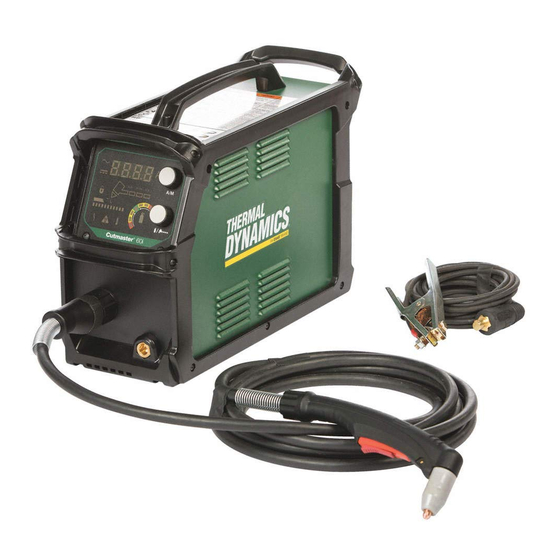
- Page 1 INPUT POWER SL60QD OUTPUT MAX OUTPUT VOLTAGE INPUT POWER 208- 480V CUTMASTER ® PLASMA CUTTING SYSTEM SERVICE MANUAL Art # A-13291 Revision: AA Issue Date: April 3, 2017 Manual No.: 0-5475 esab.com...
- Page 2 WE APPRECIATE YOUR BUSINESS! Congratulations on your new Thermal Dynamics product. We are proud to have you as our customer and will strive to provide you with the best service and reliability in the industry. This product is backed by our extensive warranty and world-wide service network. To locate your nearest distributor or service agency call 1-800-426-1888, or visit us on the web at www.esab.com.
- Page 3 2800 Airport Rd. Denton, Texas 76207 www.esab.com © Copyright 2017 by Thermal Dynamics an ESAB brand. All rights reserved. Reproduction of this work, in whole or in part, without written permission of the publisher is prohibited. The publisher does not assume and hereby disclaims any liability to any party for any loss or damage caused by any error or omission in this Manual, whether such error results from negli- gence, accident, or any other cause.
- Page 4 Be sure this information reaches the operator. You can get extra copies through your supplier. CAUTION These INSTRUCTIONS are for experienced operators. If you are not fully familiar with the principles of operation and safe practices for arc welding and cutting equipment, we urge you to read our booklet, “Precautions and Safe Practices for Arc Welding, Cutting, and Gouging,”...
- Page 5 ASSUREZ-VOUS QUE CETTE INFORMATION EST DISTRIBUÉE À L’OPÉRATEUR. VOUS POUVEZ OBTENIR DES COPIES SUPPLÉMENTAIRES CHEZ VOTRE FOURNISSEUR. ATTENTION Les INSTRUCTIONS suivantes sont destinées aux opérateurs qualifiés seulement. Si vous n’avez pas une connaissance approfondie des principes de fonctionnement et des règles de sécurité pour le soudage à l’arc et l’équipement de coupage, nous vous suggérons de lire notre brochure «...
- Page 6 This Page Intentionally Blank...
-
Page 7: Table Of Contents
TABLE OF CONTENTS SECTION 1: GENERAL INFORMATION ................1-1 1.01 Notes, Cautions and Warnings ................ 1-1 1.02 Important Safety Precautions ................. 1-1 1.03 Publications ....................1-2 SECTION 2 SYSTEM: INTRODUCTION ..................2-1 2.01 How To Use This Manual ................2-1 2.02 Equipment Identification ................. - Page 8 TABLE OF CONTENTS SECTION 6: PARTS LISTS ..................6-1 6.01 Introduction ....................6-1 6.02 Ordering Information ..................6-1 6.03 Power Supply Replacement ................6-1 6.04 Miscellaneous Replacement Power Supply Parts ........... 6-2 6.05 Options and Accessories ................6-2 6.06 External Replacement Parts (Plastic) ............. 6-3 6.07 Internal Plastics Replacement Parts ...............
-
Page 9: General Information
CUTMASTER 60i SECTION 1: To prevent possible injury, read, understand and follow all warnings, safety precautions GENERAL INFORMATION and instructions before using the equipment. Call 1-603-298-5711 or your local distributor if you have any questions. 1.01 Notes, Cautions and Warnings Throughout this manual, notes, cautions, and warnings are used to highlight important information. -
Page 10: Publications
CUTMASTER 60i • Never touch any parts that are electrically “live” or “hot.” • Wear dry gloves and clothing. Insulate yourself PLASMA ARC RAYS from the work piece or other parts of the welding Plasma Arc Rays can injure your eyes and burn your skin. - Page 11 CUTMASTER 60i PROTECTION, obtainable from American National Standards Institute, 1430 Broadway, New York, NY 10018 5. ANSI Standard Z41.1, STANDARD FOR MEN’S SAFETY-TOE FOOTWEAR, obtainable from the American National Standards Institute, 1430 Broad- way, New York, NY 10018 6. ANSI Standard Z49.2, FIRE PREVENTION IN THE...
- Page 12 CUTMASTER 60i This Page Intentionally Blank GENERAL INFORMATION Manual 0-5475...
-
Page 13: Section 2 System: Introduction
Additional copies of this manual may be purchased by contacting Thermal Dynamics at the address and phone number in your area listed on back cover of this manual. Include the Operating Manual number and equipment identification numbers. -
Page 14: Receipt Of Equipment
CUTMASTER 60i 2.03 Receipt Of Equipment When you receive the equipment, check it against the invoice to make sure it is complete and inspect the equipment for possible damage due to shipping. If there is any damage, notify the carrier immediately to file a claim. Furnish complete information concerning damage claims or shipping errors to the location in your area listed on the back cover of this manual. - Page 15 CUTMASTER 60i 3 Phase 60i 3 Phase Power Supply Specifications Input Power 208 - 480 VAC(187 - 528 VAC), 3 Phase, 50/60 Hz Power Supply includes 9' single phase 12AWG 4/C input 3 Phase Input Power Cable cable without plug..
-
Page 16: Input Wiring Specifications
Ventilation Clearance Requirements 2.05 Input Wiring Specifications WARNING Each CutMaster 60i system is a dedicated 1 Phase OR 3 Phase system and cannot be reconfigured to the other. Personal injury could occur if changing the phase is attempted.. 1 Phase... -
Page 17: Power Supply Features
CUTMASTER 60i 3 Phase 3 Phase CutMaster 60i Power Supply Input Cable Wiring Requirements Input voltage Freq Power Input Suggested Sizes Flexible Cord (Min. Volts I max Fuse (amps) AWG) 50/60 18.5 12 AWG (2.5mm 50/60 23.3 16.5 12 AWG (2.5mm 50/60 13.8... - Page 18 CUTMASTER 60i This Page Intentionally Blank INTRODUCTION Manual 0-5475...
-
Page 19: Section 3 System: Installation
CUTMASTER 60i SECTION 3 SYSTEM: INSTALLATION 3.01 Unpacking 1. Use the packing lists to identify and account for each item. 2. Inspect each item for possible shipping damage. If damage is evident, contact your distributor and / or shipping company before proceeding with the installation. -
Page 20: Opening The Main Switch Cover
Main Switch Cover 3.04 Primary Input Power Connections, SINGLE Phase WARNING Each CutMaster 60i system is a dedicated 1 Phase OR 3 Phase system and cannot be reconfigured to the other. Personal injury could occur if changing the phase is attempted.. CAUTION... -
Page 21: Primary Input Power Connections, Three Phase
CUTMASTER 60i 3.05 Primary Input Power Connections, THREE Phase WARNING Each CutMaster 60i system is a dedicated 1 Phase OR 3 Phase system and cannot be reconfigured to the other. Personal injury could occur if changing the phase is attempted.. CAUTION... -
Page 22: Gas Connections
CUTMASTER 60i 3.06 Gas Connections Connecting Gas Supply to Unit The connection is the same for compressed air or high pressure cylinders. Refer to the following two subsections if an optional air line filter is to be installed. 1. Connect the air line to the inlet port. The illustration shows typical fittings as an example. - Page 23 CUTMASTER 60i Installing Optional Single - Stage Air Filter An optional filter kit (7-7507) is recommended for improved filtering with compressed air, to keep moisture and debris out of the torch. 1. Attach the Single - Stage Filter Hose to the Inlet Port 1/4" NPT of the system filter.
- Page 24 CUTMASTER 60i Installing Optional Two - Stage Air Filter Kit This optional two - stage air line filter (9-9387) is also for use on compressed air shop systems. Filter removes mois- ture and contaminants to at least 5 microns. Connect the air supply as follows: 1.
-
Page 25: Work Lead Connections
CUTMASTER 60i Using High Pressure Air Cylinders When using high pressure air cylinders as the air supply: 1. Refer to the manufacturer’s specifications for installation and maintenance procedures for high pressure regulators. 2. Examine the cylinder valves to be sure they are clean and free of oil, grease or any foreign material. Briefly open each cylinder valve to blow out any dust which may be present. - Page 26 CUTMASTER 60i This Page Intentionally Blank INSTALLATION Manual 0-5475...
-
Page 27: Section 4 System
CUTMASTER 60i SECTION 4 SYSTEM: OPERATION 4.01 Front Panel Controls / Features See Illustration for numbering Identification Art # A-13250 Numeric Display • Displays software revision at start up • Displays amperage values (Factory default) • Displays error codes • Displays pre-set (preview) maintenance functions AC Indicator Steady light indicates power supply is ready for operation. - Page 28 CUTMASTER 60i Set Mode Indicator Indicator is ON when unit is flowing gas and pressure can be set. Shield Cup In Place Indicator Indicator is Blinking when any of the following are not in place or connected: Shield Cup, ATC leads or Quick Disconnect.
- Page 29 CUTMASTER 60i Gas Pressure Indicator Indicator used to show low, optimal and high gas pressure. Torch type, lead length, cutting mode and amperage should all be set prior to setting the gas pressure. (90 - 125 PSI / 6.2 - 8.6 bar) One of 7 segments will always be on when unit is on.
-
Page 30: Preparations For Operation
4T.07 and following for torch parts selection. Torch Connection Check that the torch is properly connected. Only Thermal Dynamics models SL60, SL60QD™ / Manual or SL100 / Mechanical Torches may be connected to this Power Supply. See Section 3T of this manual. - Page 31 CUTMASTER 60i Connect Work Cable Clamp the work cable to the workpiece or cutting table. The area must be free from oil, paint and rust. Connect only to the main part of the workpiece; do not connect to the part to be cut off.
- Page 32 CUTMASTER 60i Select Cutting Mode Art # A-13251 1. Press and release the upper knob without turning to enter the mode selection menu. Place the system in one of the four cutting modes available by pressing and releasing the knob until you reach the desired mode.:...
- Page 33 CUTMASTER 60i Set Operating Pressure NOTE! Before the gas pressure is set, the torch type, leads length, type of cutting and amperage should all be set as they will affect the pressures required. If any of those are changed, the pressure should be checked again to make sure it is optimized.
- Page 34 CUTMASTER 60i This Page Intentionally Blank OPERATION Manual 0-5475...
-
Page 35: Section 5 System
CUTMASTER 60i SECTION 5 SYSTEM: SERVICE 5.01 General Maintenance Maintain more often Warning! if used under severe Disconnect input power before maintaining. conditions Each Use Visual check of torch tip and electrode Weekly Visually inspect the cables and leads. Replace as needed... -
Page 36: Maintenance Schedule
CUTMASTER 60i 5.02 Maintenance Schedule NOTE! The actual frequency of maintenance may need to be adjusted according to the oper- ating environment. Daily Operational Checks or Every Six Cutting Hours: 1. Check torch consumable parts, replace if damaged or worn. -
Page 37: Common Faults
Penetration 2. Torch tilted too much. 3. Metal too thick. 4. Worn torch parts 5. Cutting current too low. 6. Non - Genuine Thermal Dynamics parts used 7. Incorrect gas pressure Main Arc 1. Cutting speed too slow. Extinguishes 2. Torch standoff too high from workpiece. -
Page 38: Fault Indicator
CUTMASTER 60i 5.04 Fault Indicator At initial power up, the system goes through a series of self checks before it is ready for use. If during those checks it detects something is not within proper operating parameters, a fault will occur. If that happens the Fault indicator will light followed by the Error Code , and number in the digital display. - Page 39 CUTMASTER 60i Problem - Symptom Possible Cause Recommended Action ON / OFF Switch 1. Primary power disconnect is in 1. Turn primary power disconnect switch to ON position. is ON but the A/C OFF position. Indicator does not 2. Primary fuses / breakers are 2.
- Page 40 CUTMASTER 60i Problem - Symptom Possible Cause Recommended Action Nothing happens 1. Problem in the torch and leads 1. Take Torch and Leads (Remote Pendant) to Authorized Repair when torch switch switch circuit (Remote pendant Facility. or remote switch switch circuit).
- Page 41 CUTMASTER 60i Sequence of Operation (Block Diagram) ACTION: ACTION: ACTION: ACTION: ON / OFF switch to ON Close external Select desired Operating mode Set Torch Type and disconnect switch. Lead Length. Select RESULT: RUN, RESULT: SET/PURGE AC indicator mode to Power to system.
-
Page 42: Advanced Troubleshooting Guide Pre-Tests
5.06 Advanced Troubleshooting Guide Pre-Tests Circuit description. The Cutmaster 60i includes single phase models and 3 phase models. They cannot be switched from one to the other. There are also specific models to meet CE requirements. SIMPLIFIED DIAGRAM PFC &... - Page 43 CUTMASTER 60i Resistance and Diode Tests The following tests require a meter with both a resistance (ohms), preferable X1, scale and diode measuring scale. You need to become familiar with how your meter measures diodes. Most meters apply a positive voltage on the + or red lead.
-
Page 44: Power Off Advanced Troubleshooting
CUTMASTER 60i 5.07 Power OFF Advanced Troubleshooting Power OFF Tests Checks before applying power with the power cord not plugged in: Cover Removal WARNING Disconnect primary power to the system before disassembling the torch, leads, or power supply. 1. Remove input power from the system then remove the ten, M5x0.8x16mm hex screws (5 on each side) that secure the cover assembly to the power supply. - Page 45 CUTMASTER 60i On all of these measurements measure on the terminal or the PCB pad, not the screw head. The screw has a coating that may not be conductive. 1. Measure inrush resistors. Set meter to Ohms scale. Measure from Bridge+ to square pad to the right of Bridge+. Normal resistance should be 47 ohms +/- 3.
- Page 46 CUTMASTER 60i 2. Measure bridge rectifier diodes On diode scale measure from each of the three AC terminals to GND_PRI .then measure each of the AC terminals to the terminal next on the right of BRIDGE+. . E300 CHASSIS GRN/YEL 3Ø...
- Page 47 CUTMASTER 60i Details: a. Meter + lead on GND_PRI and - lead to each of the 3 AC terminals. Normally it should measure as one diode in the forward direction (about 0.4V to 0.5V with Fluke meter). b. Reversing the leads, + on AC, - on GND_PRI, it should measure higher with voltage/resistance increas- ing (charging a capacitor).
- Page 48 CUTMASTER 60i 3. PFC Board Diode Test. Measure between Bridge + and J305-3 (assumes PFC inductors L1 & L2 remain con- nected.) E300 CHASSIS GRN/YEL 3Ø 1Ø MOV300 MOV301 MOV302 MOV304 MOV305 GND PRI BRIDGE+ K300 MOV306 TP23 15 UV...
- Page 49 CUTMASTER 60i 4. PFC Board IGBT Test. Measure between Bridge + to GND PRI (assumes PFC inductors L1 & L2 remain con- nected.). CAUTION Single phase and 3 phase PFC boards are different, have different catalog numbers! Using the wrong one may cause it to fail...
- Page 50 CUTMASTER 60i 5. Inverter Board IGBT Test. Measure J305-3 to GND PRI. E300 CHASSIS GRN/YEL 3Ø 1Ø MOV300 MOV301 MOV302 MOV304 MOV305 GND PRI BRIDGE+ K300 MOV306 TP23 15 UV LO LINE R300 R301 J302 TP22 D302 HI LINE TP21...
- Page 51 CUTMASTER 60i 6. Inverter Board Output Diode Test. With the torch removed, measure Work to NEG at the front panel ATC connector. Art # A-13331 a. With meter on diode scale place the + lead on the negative terminal of the ATC connector and the – lead on the Work lead Dinse receptacle.
- Page 52 CUTMASTER 60i 7. Inverter Board Pilot IGBT Test. Measure Tip to Work. (Torch removed from ATC) . Art # A-13332 a. With meter on diode scale place the + lead on the pilot terminal of the ATC connector and the – lead on the Work lead Dinse receptacle.
-
Page 53: Power On Advanced Troubleshooting
CUTMASTER 60i 5.08 Power ON Advanced Troubleshooting Power on tests. WARNING! Only qualified technicians using the proper equipment should attempt these tests. In all cases when advised to remove power to disconnect or replace something wait for at least one minute for capacitors to bleed down before touching internal parts. - Page 54 CUTMASTER 60i Unless otherwise stated GND _PRI is the common for all primary side voltage measurements. For secondary mea- surements the Work lead or its Dinse socket can be used for secondary common. The following tests are intended to done in the sequence presented. Skipping steps, unless direct to, can result in incorrect diagnosis.
- Page 55 CUTMASTER 60i d. If all the LEDS now light there is a short at the other end of either the J302 or J303 harness. Plug them in one at a time to determine which one is loading the Bias down.
- Page 56 CUTMASTER 60i ii. If +15V is present on the ribbon cable replace the Control & Display board. iii. Unlikely that both pin 5 and pin 6 of the ribbon are open at the same time but to be sure check them for continuity.
- Page 57 CUTMASTER 60i Fan runs only high speed prior to pressing the torch trigger: J608-3, speed control wire, is typically 6-7V in high speed and pulled to near zero by the Inverter board for low speed. a. Measure J608-3(+) to J608-2 (or work lead), if near zero volts replace the fan. If higher, greater than 1V (typically 6-7V), replace the Inverter board.
- Page 58 CUTMASTER 60i If there is no gas flow, after a couple seconds the display should show E016. If it does show E016 skip to “d.”. If it does not and it is not an SL100SV (automation) torch then the PS1 pressure sensor may be defective. Skip to “e.”...
- Page 59 CUTMASTER 60i 2. Pull torch trigger or apply Start, nothing happens. (Trigger or Start problem). a. START LED (D643) on the Inverter board should come on when the torch trigger is on or CNC Start (if equipped) is applied. If it does not measure voltage at J607-3(+) to J607-4 or work lead (common). Volt- age should be high, 12 to 15V, with the trigger/Start off and go to near zero with the trigger/Start on.
- Page 60 CUTMASTER 60i 4. No pilot, slow cycling of gas, about once every 5 seconds (No pilot connection). a. No or intermittent connection somewhere between the torch tip and the stud labeled TIP on the inverter board. This is an unlikely fault because if this connection is open during startup it results in E005 fault.
- Page 61 CUTMASTER 60i 9. Poor cut quality, short tip life, especially at higher current setting. May be caused by a shorted pilot IGBT. a. With shorted pilot SW total output current doesn’t change but some of the total will flow through the shorted SW instead of cutting the metal and increases the tip wear.
-
Page 62: Fault Code
CUTMASTER 60i 5.09 Fault Code Fault Code Section All fault codes also illuminate the fault symbol. 1. E001, Over Temp. E001 illuminates the temperature symbol as well as the fault symbol. A temperature fault that is not due to exceeding the duty cycle, i.e. shows up at power on or soon after, is likely a hardware problem. Temperature is measured on the heatsink of both the PFC board and the Inverter board. - Page 63 CUTMASTER 60i b. Low or sagging line. Low can be measured, should be at least 185 VAC. A line sagging under load is difficult to detect as it only sags during the load and as soon as the fault appears the load gets removed.
- Page 64 CUTMASTER 60i e. E002 at Transfer: i. An AC line that can’t supply enough current can cause the incoming voltage to sag as discussed in step a. Assuming that is not the case it is likely only half of the PFC is working. Check the routing of the inductor leads as explained in d.
- Page 65 CUTMASTER 60i Other common cause is one of the parts, tip, electrode or start cartridge, is missing. Install new parts. If still E005 do the following: a. If the Inverter board has just been replaced, a common cause of E005 is the wire #6 from the brass fitting at the back of the front panel ATC isn’t connected to the Faston tab J611 (Electrode).
- Page 66 CUTMASTER 60i 6. E010, Low Output Current Fault Art # A-13342 a. If the inverter board pilot IGBT is shorted some current will return through the IGBT bypassing the work lead current sensor. Perform the resistance tests at #7 of the "Power Off Tests".
- Page 67 CUTMASTER 60i d. A faulty voltage measurement circuit on the Inverter board might cause the unit to not recognize that there was voltage on the electrode. You can remove the ribbon cable from the Control & Display board and with the unit powered up (the display will not be on). Measure between common at pin 50 of the ribbon cable connector (or the work lead) and pin 13.
-
Page 68: Advanced Features Menu
CUTMASTER 60i 5.10 Advanced Features Menu Advanced Features Menu Entering the advanced features menu allows monitoring the following: • Pressure (in PSI) • Number of Pilot Starts • Volts electrode to work • Current, both pilot and transferred. • Arc hours displayed in tenths of hours. -
Page 69: Power Supply Basic Parts Replacement
CUTMASTER 60i 5.11 Power Supply Basic Parts Replacement WARNING Disconnect primary power to the system before disassembling the torch, leads, or power supply. This section describes procedures for basic parts replacement. For more detailed parts replacement procedures, refer to the Power Supply Service Manual. - Page 70 CUTMASTER 60i 3. Remove the filter element and clean or replace.. NOTE! If replacing or cleaning just the filter ele- ment refer to the following illustration for disassembly. Filter Element Art # A-07990 4. Install the new or cleaned assembly by reversing these procedures.
- Page 71 CUTMASTER 60i Optional Single-Stage Filter Element Replacement These instructions apply to power supplies where the optional Single-Stage Filter has been installed. The Power Supply shuts down automatically when the Filter Element becomes completely saturated. The Filter Element can be removed from its housing, dried, and reused. Allow 24 hours for Element to dry. Refer to Section 6, Parts List, for replacement filter element catalog number.
- Page 72 CUTMASTER 60i Optional Two-Stage Filter Element Replacement The Two-Stage Air Filter has two Filter Elements. When the Filter Elements become dirty the Power Supply will continue to operate but cut quality may become unacceptable. Refer to Section 6, Parts List, for replacement filter element catalog number.
-
Page 73: Internal Parts Replacement
CUTMASTER 60i 5.12 Internal Parts Replacement Cover Removal WARNING Disconnect primary power to the system before disassembling the torch, leads, or power supply. 1. Remove input power from the system then remove the ten, M5x0.8x16mm hex screws (5 on each side) that secure the cover assembly to the power supply. - Page 74 CUTMASTER 60i Fan Replacement After cover removal you can access fan on the top of the power supply. To remove the fan do the following: NOTE! Note the orientation of the fan and where the wires are routed from the fan so you are able to install the new fan exactly the same way.
- Page 75 CUTMASTER 60i Pressure Control Solenoid After the cover is removed, you can access the Pressure Control Solenoid which is located on the inside of the power supply and attached to the back of the input air filter. To replace, do the following: 1.
- Page 76 CUTMASTER 60i 3. Remove the two M5x0.8x16mm hex screws, at the rear of the unit holding the filter assembly in place. Remove these two screws Art # A-13314 4. Remove the entire assembly out through the rear of the unit...
- Page 77 CUTMASTER 60i Control Panel WARNING Disconnect primary power to the system before disassembling the torch, leads, or power supply. The cover does not have to be removed to replace the Control Panel. The following illustrations show the cover removed. 1. Remove the two M5x0.8x12mm hex screws at the bottom corners of the Control Panel.
- Page 78 CUTMASTER 60i Bias Supply PCB removal WARNING Disconnect primary power to the system before disassembling the torch, leads, or power supply. The Bias Supply PCB is located to the rear of the center chassis on the right side of the unit under the input power switch.
- Page 79 CUTMASTER 60i PFC PCB removal WARNING Disconnect primary power to the system before disassembling the torch, leads, or power supply. The PFC PCB is located on the right side of the system behind the air shroud. After the cover is removed it can be removed by following these steps.
- Page 80 CUTMASTER 60i 2. Locate and identify each wire or harness attached to the PFC PCB for re-attachment later. 3. Disconnect each wire or harness at location indicated in the following illustration with a dotted line circle. 4. Remove the three nuts along the top and loosen the two bottom ones indicated by the dotted line squares in the illustration below.
- Page 81 CUTMASTER 60i Inverter PCB removal WARNING Disconnect primary power to the system before disassembling the torch, leads, or power supply. Overview: In this process you will remove the cover, remove the fan assembly, remove the filter assembly and disconect all wires, harnesses before removing the Inverter PCB .
- Page 82 CUTMASTER 60i 4. Remove the fan assembly and the air shroud as shown in following illustration. Art # A-13322 5. Disconnect the remaining electrical connections to the Inverter PCB which will include 6 ring terminals with nuts and one fast-on connection located at the bottom right of the board.
- Page 83 CUTMASTER 60i 6. Everything should be disconnected from the Inverter PCB at this time. Next remove the five (5) nuts along the top of the PCB and only loosen the two (2) in the bottom corners. Art # A-13324 Loosen ONLY 7.
- Page 84 CUTMASTER 60i 3 Unplug the harness from the HCT1 and disconnect the air/gas tube and connector from the brass tube on the ATC connector. Art # A-13338 4. Remove nut and ring terminal and lead that runs through the HCT1 from ATC as shown Art # A-13339 5.
-
Page 85: Parts Lists
The following items are included with the replacement power supply: work cable & clamp, input power cable, gas pressure regulator / filter, and operating manual. Description Catalog # CutMaster 60i Power Supply 208/230 - 480VAC, SINGLE Phase, 60Hz, with input power cable and plug for 208/230VAC 3-5630-1... - Page 86 CUTMASTER 60i 6.04 Miscellaneous Replacement Power Supply Parts Description Catalog # Filter Assembly Replacement Element (Factory filter) 9-0116 SINGLE phase Input Power Cord for 208/230 V Power Supply 9-9701 THREE phase Input Power Cord for 208/480 V Power Supply 9-9706 6.05...
-
Page 87: External Replacement Parts (Plastic)
CUTMASTER 60i 6.06 External Replacement Parts (Plastic) Item # Description Catalog # Handle, Case Top 9-9702 Bezel, Side Frame RH 9-9703 Handle, CM60i (3 total) 9-9665 Foot, Case Front 9-9694 Bezel, Side Frame LH 9-9704 Foot, Case Rear 9-9693 Screws and nuts can be obtained at a local hardware store. -
Page 88: Internal Plastics Replacement Parts
CUTMASTER 60i 6.07 Internal Plastics Replacement Parts Item # Description Catalog # Fan, 24V 2.63A, 283CFM 9-9670 Shroud, Inverter Fan MNT (mount) 9-9684 Shroud, PFC 10.2KW 9-9690 Shroud, Inverter 10.2KW 9-9691 Mount, Switch 3PH SB 9-9676 Switch, CB 63A 460VAC 3P... -
Page 89: Left Side Replacement Parts
CUTMASTER 60i 6.08 Left Side Replacement Parts PCB, Inverter 10.2KW 9-9671 Pressure Transducer Assy. 9-9681 PCB, Control BRD CMi 9-9688 Assy, Control Board 9-9677 Knob, 25mm 6mmx4mm D shaft 9-9678 Assy, ATC conn pwr sup 9-9668 Assy, Transformer 300V 30K... -
Page 90: Right Side Replacement Parts
CUTMASTER 60i 6.09 Right Side Replacement Parts Item # Description Catalog # PFC, 1Phase 10.2KW 9-9673 PFC, 3 Phase 10.2 KW 9-9705 Bridge Rectifier, 3Phase 9-9686 PCB, Bias 1PH/3PH 10.2 KW 9-9674 Inductor, PFC, CM60i (2 total) 9-9685 Connector, 50mm Dinse Panel Mount... -
Page 91: Replacement Parts For Hand Torch
CUTMASTER 60i 6.10 Replacement Parts for Hand Torch Item # Description Catalog # Torch Handle Assembly Replacement 7-5680 Leads Assemblies with ATC connector and Quick Connectors SL60QD™, 20 - foot Leads Assembly with ATC and QD connectors 4-5604 SL60QD™, 50 - foot Leads Assembly with ATC connector 4-5605 1&2... -
Page 92: Torch Consumable Parts (Sl60)
CUTMASTER 60i 6.11 Torch Consumable Parts (SL60) 9-8252 9-8218 (60A) 9-8235 9-8243 9-8237 Replace Consumables. 9-8210 Remplacer les consommables. (60A) 8-3487 8-3486 9-8218 9-8281 9-8215 Std Life 9-8226 B 9-8241 9-8213 9-8237 Torch Head 9-8214 Ext Life (60A) 23x6005 Art # A-13147_AC... -
Page 93: Torch Consumable Parts
CUTMASTER 60i 6.12 Torch Consumable Parts 20-40A Shield Tip: Shield Cap, Machine Cup Body, STANDOFF 40A 9-8245 9-8237 CUTTING 9-8205 Shield Cap, Deflector Shield Cup 9-8206 9-8243 9-8218 9-8208 Drag Shield Cup 9-8235 50-60A Shield Tips: STANDOFF Cup Body, CUTTING... - Page 94 CUTMASTER 60i This Page Intentionally Blank PARTS LIST Manual 0-5475 6-10...
-
Page 95: Appendix 1: Data Tag Information
CUTMASTER 60i APPENDIX 1: DATA TAG INFORMATION Manufacturer's Name and/or Hermosillo, Sonora, Mexico Logo, Location, Model and Revision Level, Serial Number Model: and Production Code Date of Mfr: Made in Mexico Type of Power Regulatory Standard Covering 1 or 3... -
Page 96: Appendix 2: Torch Pin - Out Diagrams
CUTMASTER 60i APPENDIX 2: TORCH PIN - OUT DIAGRAMS A. Hand Torch Pin - Out Diagram ATC Female Receptacle ATC Male Connector Front View Front View Negative / Negative / Plasma Plasma 8 - Open 8 - Ground 4 - Green /... -
Page 97: Appendix 3: Torch Connection Diagrams
CUTMASTER 60i APPENDIX 3: TORCH CONNECTION DIAGRAMS A. Hand Torch Connection Diagram Torch: SL60QD / SL60 / SL100 Hand Torch Leads: Torch Leads with ATC Connector Power Supply: 60i Male ATC Leads ATC Female Power Connector Receptacle Torch Torch Supply... -
Page 98: Appendix 4: System Schematic, 1Phase 208/460V Units
CUTMASTER 60i APPENDIX 4: SYSTEM SCHEMATIC, 1PHASE 208/460V UNITS (16) PFC PCB INPUT & BIAS SUPPLY PCB IND1 OUT D300 1 (+) RECT+ 7 (K) IND2 OUT 6 (G) BLUE BUS_+ J301 208-480 VAC +/- 10% (16) 1 Phase. CONTROL... - Page 99 CUTMASTER 60i HCT1 1TORCH INVERTER PCB J401 PIP SW J601 +15V TORCH TRIGGER -15V IN_+ SOL * J606 PRI 1 AUTOMATION D633 J607 TORCH ONLY ELECTRODE SEC 1 Q608 PRI 2 D635 GND_PRI Work GND PRI SEC 2 WORK J604 - HIPOT...
-
Page 100: Appendix 5: System Schematic, 3Phase 208/460V Units
CUTMASTER 60i APPENDIX 5: SYSTEM SCHEMATIC, 3PHASE 208/460V UNITS (16) PFC PCB INPUT & BIAS SUPPLY PCB IND1 OUT D300 1 (+) RECT+ 7 (K) IND2 OUT 6 (G) BLUE BUS_+ J301 (16) CONTROL J305 GND_PRI J304 - HIPOT PFC TEMP SIG... - Page 101 CUTMASTER 60i HCT1 1TORCH INVERTER PCB J401 PIP SW J601 +15V TORCH TRIGGER -15V IN_+ SOL * J606 PRI 1 AUTOMATION D633 J607 TORCH ONLY ELECTRODE SEC 1 Q608 PRI 2 D635 GND_PRI Work GND PRI SEC 2 WORK J604 - HIPOT...
-
Page 102: Appendix 6: Publication History
CUTMASTER 60i APPENDIX 6: Publication History Cover Date Rev. Change(s) Apr. 3, 2017 Manual released. APPENDIX Manual 0-5475... - Page 103 This Page Intentionally Blank...
- Page 104 THE AMERICAS Denton, TX USA U.S. Customer Care Ph 1-800-426-1888 (tollfree) Fax: 1-800-535-0557 (tollfree) International Customer Care Ph 1-940-381-1212 Fax: 1-940-483-8178 Miami, FL USA Sales Office, Latin America Ph 1-954-727-8371 Fax: 1-954-727-8376 Oakville, Ontario, Canada Canada Customer Care Ph 1-905-827-4515 Fax: 1-800-588-1714 (tollfree) U.S.
Need help?
Do you have a question about the CUTMASTER 60i and is the answer not in the manual?
Questions and answers