Thermal Dynamics A60 CUTMASTER Operating Manual
Automated plasma cutting system
Hide thumbs
Also See for A60 CUTMASTER:
- Operating manual (118 pages) ,
- Service manual (148 pages) ,
- Operating manual (98 pages)

Related Manuals for Thermal Dynamics A60 CUTMASTER


Summary of Contents for Thermal Dynamics A60 CUTMASTER
- Page 1 CutmASteR ™ AutomAted PLASmA CuttING SYStem Art # A-08952_AB operating manual Rev. AK Date: February 25, 2010 Manual # 0-4981 Operating Features: Duty Cycle...
- Page 2 1888, or visit us on the web at www.thermal-dynamics.com. This Operating Manual has been designed to instruct you on the correct use and operation of your Thermal Dynamics product. Your satisfaction with this product and its safe operation is our ultimate concern.
- Page 3 Manufacturer assumes no liability for its use. Plasma Cutting Power Supply CutMaster™ A60 SL100 ™ SV Automated Torch Operating Manual Number 0-4981 Published by: Thermal Dynamics Corporation 82 Benning Street West Lebanon, New Hampshire, USA 03784 (603) 298-5711 www.thermal-dynamics.com Copyright 2008, 2009, 2010 by Thermadyne Corporation All rights reserved.
- Page 4 This Page Intentionally Blank...
-
Page 5: Table Of Contents
TABLE OF CONTENTS SECTION 1:GENERAL INFORMATION ...................1-1 1.01 Notes, Cautions and Warnings ................1-1 1.02 Important Safety Precautions ................1-1 1.03 Publications ......................1-2 1.04 Note, Attention et Avertissement ................1-3 1.05 Precautions De Securite Importantes ..............1-3 1.06 Documents De Reference ..................1-5 1.07 Declaration of Conformity ..................1-6 1.08 Statement of Warranty ..................1-7 SECTION 2 SYSTEM:INTRODUCTION .................2-1... - Page 6 TABLE OF CONTENTS PATENT INFORMATION ...................... 4T-46 SECTION 5 SYSTEM:SERVICE ....................5-1 5.01 General Maintenance....................5-1 5.02 Maintenance Schedule ..................5-2 5.03 Common Faults .....................5-2 5.04 Fault Indicator .......................5-3 5.05 Basic Troubleshooting Guide ................5-4 5.06 Circuit Fault Isolation ....................5-6 SECTION 5 TORCH:SERVICE ....................5T-1 5T.01 General Maintenance..................
-
Page 7: Section 1:General Information
cutmaster a60 SECTION 1: • The kinds of fumes and gases from the plasma arc depend on the kind of metal being used, coatings on the metal, and the GENERAL INFORMATION different processes. You must be very careful when cutting or welding any metals which may contain one or more of the following: 1.01... -
Page 8: Publications
cutmaster a60 • Do not cut or weld on containers that may have held combus- 1.03 Publications tibles. Refer to the following standards or their latest revisions for more • Provide a fire watch when working in an area where fire hazards information: may exist. -
Page 9: Note, Attention Et Avertissement
cutmaster a60 1.04 Note, Attention et Avertissement • Les sortes de gaz et de fumée provenant de l’arc de plasma dépen- dent du genre de métal utilisé, des revêtements se trouvant sur le Dans ce manuel, les mots “note,” “attention,” et “avertissement” sont métal et des différents procédés. - Page 10 cutmaster a60 produit du métal, des étincelles, des scories chaudes pouvant mettre le feu aux matières combustibles ou provoquer l’explosion de fumées inflammables. BRUIT • Soyez certain qu’aucune matière combustible ou inflammable ne Le bruit peut provoquer une perte permanente de l’ouïe. Les procédés se trouve sur le lieu de travail.
-
Page 11: Documents De Reference
cutmaster a60 1.06 Documents De Reference 14. Norme AWSF4.1 de l’Association Américaine de Soudage, RECOM- MANDATIONS DE PRATIQUES SURES POUR LA PRÉPARATION À Consultez les normes suivantes ou les révisions les plus récentes ayant LA COUPE ET AU SOUDAGE DE CONTENEURS ET TUYAUX AYANT été... -
Page 12: Declaration Of Conformity
Thermal Dynamics has been manufacturing products for more than 30 years, and will continue to achieve excellence in our area of manufacture. -
Page 13: Statement Of Warranty
This warranty is exclusive and in lieu of any warranty of merchantability or fitness for a particular purpose. Thermal Dynamics will repair or replace, at its discretion, any warranted parts or components that fail due to defects in material or workmanship within the time periods set out below. - Page 14 cutmaster a60 GENERAL INFORMATION Manual 0-4981...
-
Page 15: Section 2 System:introduction
Electronic copies of this manual can also be downloaded at no charge in Acrobat PDF format by going to the Thermal Dynamics web site listed below and clicking on Thermal Dynamics and then on the Literature link: http://www.thermal-dynamics.com... -
Page 16: Power Supply Specifications
cutmaster a60 2.04 Power Supply Specifications CutMaster A60 Power Supply Specifications 208 / 230 VAC (187 - 253 VAC), Single Phase, 60 Hz 230 VAC (187 - 253 VAC), Three Phase, 50/60 Hz 380 VAC (360 - 440 VAC), Three Phase, 50/60 Hz Input Power 400 VAC (360 - 440 VAC), Three Phase, 50/60 Hz 460 VAC (414 - 506 VAC), Single Phase, 60 Hz... -
Page 17: Input Wiring Specifications
cutmaster a60 2.05 Input Wiring Specifications CutMaster A60 Power Supply Input Cable Wiring Requirements Input voltage Freq Power Input Suggested Sizes Flexible Cord Volts I max I eff Fuse (amps) (Min. AWG) 1 Phase 50/60 50/60 11.8 3 Phase 50/60 11.8 Line Voltages with Suggested Circuit Protection and Wire Sizes Based on National Electric Code and Canadian Electric Code... -
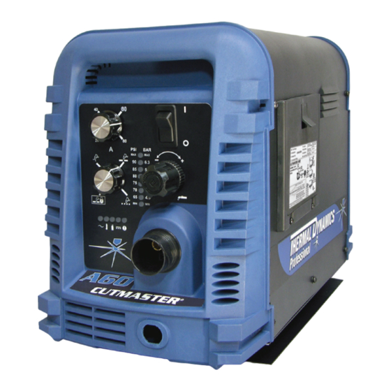
Page 18: Power Supply Features
cutmaster a60 2.06 Power Supply Features Control Panel Art # A-08306 Torch Leads Receptacle Mounting Rails Work Cable and Clamp Automation Interface Cable Port Input Power Selection Filter Assembly Gas Inlet Port Input Power Cord Art # A-08318 INTRODUCTION Manual 0-4981... -
Page 19: Section 2 Torch:introduction
cutmaster a60 SECTION 2 TORCH: 2T.03 Specifications INTRODUCTION A. Torch Configurations 1. Automation Torch, Model 2T.01 Scope of Manual The standard automation torch has a position- ing tube with rack & pinch block assembly and This manual contains descriptions, operating a solenoid valve. instructions and maintenance procedures for the 18.875"... -
Page 20: 04 Options And Accessories
cutmaster a60 C. Torch Parts NOTE Operating pressure varies with torch model, op- Starter Cartridge, Electrode, Tip, Shield Cup erating amperage, and torch leads length. Refer to D. Parts - In - Place (PIP) gas pressure settings charts for each model. Torch Head has built - in switch H. - Page 21 cutmaster a60 E. Parts - In - Place (PIP) By forcing the plasma gas and electric arc through a small orifice, the torch delivers a high concentration The torch includes a 'Parts - In - Place' (PIP) circuit. of heat to a small area. The stiff, constricted plasma When the shield cup is properly installed, it closes arc is shown in Zone C.
- Page 22 cutmaster a60 This Page Intentionally Blank INTRODUCTION 2T-4 Manual 0-4981...
-
Page 23: Section 3 System: Installation
cutmaster a60 SECTION 3 SYSTEM: 3.03 Power Supply location and Mounting INSTALLATION NOTE 3.01 Unpacking It is recommended that the unit be secured to a suitable surface using the mounting rails. 1. Use the packing lists to identify and ac- 1. - Page 24 cutmaster a60 A. Cover Removal C. Input Power Selection 1. Remove the upper and lower screws Set the Input Voltage Selection Switch at the rear which secure the cover to the main assem- of the unit based on the primary input voltage it bly.
- Page 25 cutmaster a60 9. Connect the opposite end of individual E. Connections to Single Phase Input Power wires to a customer supplied plug or main disconnect. 10. Connect the input power cable (or close WARNING the main disconnect switch) to supply Disconnect input power from the power power.
-
Page 26: Gas Connections
cutmaster a60 6. Connect the wires as follows. Filter Assembly • Remove the copper bus bar jumper from L2 and L3 on the contactor. See Inlet Port previous illustration. • Green / Yellow wire to Ground. • Remaining wires to L1, L2 and L3 in- Hose Clamp put. - Page 27 cutmaster a60 Installing Optional Two - Stage Air Filter Kit Filter Assembly This optional two - stage air line filter is also for use on compressed air shop systems. Filter Inlet Port removes moisture and contaminants to at least 5 microns.
- Page 28 cutmaster a60 Using High Pressure Air Cylinders When using high pressure air cylinders as the air supply: 1. Refer to the manufacturer’s specifications for installation and maintenance proce- dures for high pressure regulators. 2. Examine the cylinder valves to be sure they are clean and free of oil, grease or any foreign material.
-
Page 29: Section 3 Torch: Installation
3T.01 Torch Connections 2. Put the Function Control switch in the SET If necessary, connect the torch to the Power Sup- ply. Connect only the Thermal Dynamics model position. SL100SV / Automation, SL100 / Mechanical 3. Place a welding filter lens in front of the or SL60 / Manual Torch to this power supply. - Page 30 cutmaster a60 3T.03 Setting Up Automation or Machine Torch NOTE An adapter is required to be installed in the power supply if converting a hand torch system to oper- ate a machine or automation torch. WARNING Disconnect primary power at the source be- fore disassembling the torch or torch leads.
-
Page 31: Section 4 System: Operation
cutmaster a60 SECTION 4 SYSTEM: OPERATION 4.01 Front Panel Controls / Features See Illustration for numbering Identification 1. Output Current Control Sets the desired output current. Output settings up to 60 Amps may be used for drag cutting (with the torch tip contacting the workpiece) or higher for standoff cutting. -
Page 32: Preparations For Operation
Set Operating Pressure Check that the torch is properly connected. Only 1. Place the Power Supply Function Control Thermal Dynamics model SL60 / Manual, SL100 / knob to the SET position. Gas will Mechanical or SL100 / SV Automation Torches may be connected to this Power Supply. - Page 33 cutmaster a60 LATCH position the main cutting arc will be main- STANDOFF tained after the torch switch is released. CutMaster A60 Gas Pressure Settings Typical Cutting Speeds SL100 Leads SL60 (Mechanized Torch) Cutting speeds vary according to torch output am- Length (Hand Torch) SL 100 SV...
- Page 34 cutmaster a60 This Page Intentionally Blank OPERATION Manual 0-4981...
-
Page 35: Section 4 Torch:operation
cutmaster a60 SECTION 4 TORCH: For optimum smooth surface quality, the travel speed should be adjusted so that only the leading OPERATION edge of the arc column produces the cut. If the travel speed is too slow, a rough cut will be produced as the arc moves from side to side in search of metal 4T.01 Machine and Automated Torch for transfer. -
Page 36: 02 Automation Torch Parts Selection
cutmaster a60 4T.02 Automation Torch Parts Torch Head Art # A-04173_AB Selection Electrode Check the torch for proper consumable parts. The parts supplied in the torch may not be correct for the operator’s chosen amperage level. The torch parts Start Cartridge must correspond with the type of operation. -
Page 37: 04 Cut Quality
cutmaster a60 4T.04 Cut Quality NOTE Refer to Section 4T.08 and following for additional NOTES information on torch parts. Cut quality depends heavily on setup and Change the torch parts for a different operation as parameters such as torch standoff, alignment with follows: the workpiece, cutting speed, gas pressures, and operator ability. -
Page 38: 05 General Cutting Information
cutmaster a60 Bottom Dross Buildup Edge Starting Molten material which is not blown out of the cut For edge starts, hold the torch perpendicular to the area and resolidifies on the plate. Excessive dross workpiece with the front of the tip near (not touch- may require secondary cleanup operations after ing) the edge of the workpiece at the point where cutting. -
Page 39: 06 Hand Torch Operation
cutmaster a60 4. Slide the trigger release toward the back 4T.06 Hand Torch Operation of the torch handle while simultaneously Standoff Cutting With Hand Torch squeezing the trigger. The pilot arc will start. NOTE For best performance and parts life, always use the correct parts for the type of operation. - Page 40 cutmaster a60 NOTE Drag Cutting With a Hand Torch When the shield cup is properly installed, there Drag cutting works best on metal 1/4" (6 mm) thick is a slight gap between the shield cup and the or less. torch handle. Gas vents through this gap as part NOTE of normal operation.
- Page 41 cutmaster a60 3. In a portion of the unwanted metal start the Trigger pierce off the cutting line and then continue the cut onto the line. Hold the torch per- pendicular to the workpiece after the pierce is complete. 4. Hold the torch away from your body. Trigger Release 5.
-
Page 42: 07 Gouging
cutmaster a60 Cutting speed depends on material, thickness, Torch Travel Speed and the operator’s ability to accurately follow the NOTE desired cut line. The following factors may have Refer to Appendix Pages for additional information an impact on system performance: as related to the Power Supply used. - Page 43 cutmaster a60 Slag Buildup Slag generated by gouging on materials such as carbon and stainless steels, nickels, and alloyed steels, can be removed easily in most cases. Slag does not obstruct the gouging process if it accumulates to the side of the gouge path.
-
Page 44: 08 Recommended Cutting Speeds For Machine And Automated Torches With Exposed Tip
cutmaster a60 4T.08 Recommended Cutting Speeds for Machine and Automated Torches With Exposed Tip Mild Steel Air Plasma / Air Shield Standard Shield Cup Deflector Starter Cartridge Electrode Maximum Life Shield Cup 9-8218 9-8243 9-8208 9-8213 9-8232 9-8237 Torch Initial Kerf Width Gas Pressure Material... - Page 45 cutmaster a60 Torch Initial Kerf Width Material Gas Pressure Arc Voltage Working Travel Speed Piercing Pierce Delay @ Rec. Thickness (Air) Height Height Speed (mm) (torch lead Volts (mm) (mm/min) (mm) (sec) (mm) length) 3990 2920 1810 1470 4.8 (7.6m) 1345 5.2 (15.2m) 1100...
- Page 46 cutmaster a60 Stainless Steel Air Plasma / Air Shield Standard Shield Cup Deflector Starter Cartridge Electrode Maximum Life Shield Cup 9-8218 9-8243 9-8208 9-8213 9-8232 9-8237 Torch Initial Kerf Width Gas Pressure Material Arc Voltage Working Travel Speed Piercing Pierce Delay @ Rec.
- Page 47 cutmaster a60 Torch Initial Kerf Width Material Gas Pressure Arc Voltage Working Travel Speed Piercing Pierce Delay @ Rec. Thickness (Air) Height Height Speed (mm) (torch lead Volts (mm) (mm/min) (mm) (sec) (mm) length) 1670 1140 5.2 (7.6) 5.5 (15.2) Edge Start BOLD TYPE indicates maximum piercing parameters.
- Page 48 cutmaster a60 Aluminum Air Plasma / Air Shield Standard Shield Cup Deflector Starter Cartridge Electrode Maximum Life Shield Cup 9-8218 9-8243 9-8208 9-8213 9-8232 9-8237 Torch Initial Kerf Width Gas Pressure Material Arc Voltage Working Travel Speed Piercing Pierce Delay @ Rec.
- Page 49 cutmaster a60 Torch Initial Kerf Width Material Gas Pressure Arc Voltage Working Travel Speed Piercing Pierce Delay @ Rec. Thickness (Air) Height Height Speed (mm) (torch lead Volts (mm) (mm/min) (mm) (sec) (mm) length) 7620 3500 2350 4.8 (7.6m) 2170 1740 5.2 (15.2m) 1015...
- Page 50 cutmaster a60 Mild Steel Air Plasma / Air Shield Standard Shield Cup Deflector Starter Cartridge Electrode Maximum Life Shield Cup 9-8218 9-8243 9-8210 9-8213 9-8232 9-8237 Torch Initial Kerf Width Gas Pressure Material Arc Voltage Working Travel Speed Piercing Pierce Delay @ Rec.
- Page 51 cutmaster a60 Torch Initial Kerf Width Material Gas Pressure Arc Voltage Working Travel Speed Piercing Pierce Delay @ Rec. Thickness (Air) Height Height Speed (mm) (torch lead Volts (mm) (mm/min) (mm) (sec) (mm) length) 7540 7015 0.10 4570 0.10 3650 0.20 2465 0.20...
- Page 52 cutmaster a60 Stainless Steel Air Plasma / Air Shield Standard Shield Cup Deflector Starter Cartridge Electrode Maximum Life Shield Cup 9-8218 9-8243 9-8210 9-8213 9-8232 9-8237 Torch Initial Kerf Width Gas Pressure Material Arc Voltage Working Travel Speed Piercing Pierce Delay @ Rec.
- Page 53 cutmaster a60 Torch Initial Kerf Width Material Gas Pressure Arc Voltage Working Travel Speed Piercing Pierce Delay @ Rec. Thickness (Air) Height Height Speed (mm) (torch lead Volts (mm) (mm/min) (mm) (sec) (mm) length) 10890 0.00 7560 0.10 4365 0.10 2865 0.20 2195...
- Page 54 cutmaster a60 Aluminum Air Plasma / Air Shield Standard Shield Cup Deflector Starter Cartridge Electrode Maximum Life Shield Cup 9-8218 9-8243 9-8210 9-8213 9-8232 9-8237 Torch Initial Kerf Width Gas Pressure Material Arc Voltage Working Travel Speed Piercing Pierce Delay @ Rec.
- Page 55 cutmaster a60 Torch Initial Kerf Width Material Gas Pressure Arc Voltage Working Travel Speed Piercing Pierce Delay @ Rec. Thickness (Air) Height Height Speed (mm) (torch lead Volts (mm) (mm/min) (mm) (sec) (mm) length) 17010 0.00 7680 0.10 6410 0.10 5230 0.20 4010...
- Page 56 cutmaster a60 Mild Steel Air Plasma / Air Shield Standard Shield Cup Deflector Starter Cartridge Electrode Maximum Life Shield Cup 9-8218 9-8243 9-8211 9-8213 9-8232 9-8237 Torch Initial Kerf Width Gas Pressure Material Arc Voltage Working Travel Speed Piercing Pierce Delay @ Rec.
- Page 57 cutmaster a60 Torch Initial Kerf Width Material Gas Pressure Arc Voltage Working Travel Speed Piercing Pierce Delay @ Rec. Thickness (Air) Height Height Speed (mm) (torch lead Volts (mm) (mm/min) (mm) (sec) (mm) length) 8915 0.00 7415 0.10 5915 0.10 4095 0.30 3325...
- Page 58 cutmaster a60 Stainless Steel Air Plasma / Air Shield Standard Shield Cup Deflector Starter Cartridge Electrode Maximum Life Shield Cup 9-8218 9-8243 9-8211 9-8232 9-821 9-8237 Torch Initial Kerf Width Gas Pressure Material Arc Voltage Working Travel Speed Piercing Pierce Delay @ Rec.
- Page 59 cutmaster a60 Torch Initial Kerf Width Material Gas Pressure Arc Voltage Working Travel Speed Piercing Pierce Delay @ Rec. Thickness (Air) Height Height Speed (mm) (torch lead Volts (mm) (mm/min) (mm) (sec) (mm) length) 9020 0.00 8380 0.00 7730 0.10 5865 0.20 3410...
- Page 60 cutmaster a60 Aluminum Air Plasma / Air Shield Standard Shield Cup Deflector Starter Cartridge Electrode Maximum Life Shield Cup 9-8218 9-8243 9-8211 9-8213 9-8232 9-8237 Torch Initial Kerf Width Gas Pressure Material Arc Voltage Working Travel Speed Piercing Pierce Delay @ Rec.
- Page 61 cutmaster a60 Torch Initial Kerf Width Material Gas Pressure Arc Voltage Working Travel Speed Piercing Pierce Delay @ Rec. Thickness (Air) Height Height Speed (mm) (torch lead Volts (mm) (mm/min) (mm) (sec) (mm) length) 0.00 8890 8420 0.00 0.10 7170 5710 0.20 0.20...
-
Page 62: 09 Recommended Cutting Speeds For Machine And Automated Torches With Shielded Tip
cutmaster a60 4T.09 Recommended Cutting Speeds for Machine and Automated Torches With Shielded Tip Mild Steel Air Plasma / Air Shield Shield Cap Maximum Life Shield Cup Starter Cartridge Electrode 9-8245 9-8237 9-8208 9-8213 9-8232 Torch Initial Kerf Width Gas Pressure Material Arc Voltage Working... - Page 63 cutmaster a60 Torch Initial Kerf Width Material Gas Pressure Arc Voltage Working Travel Speed Piercing Pierce Delay @ Rec. Thickness (Air) Height Height Speed (mm) (torch lead Volts (mm) (mm/min) (mm) (sec) (mm) length) 3266 2239 1794 1651 5.2 (7.6) 1578 5.5 (15.2) 1256...
- Page 64 cutmaster a60 Stainless Steel Air Plasma / Air Shield Shield Cap Maximum Life Shield Cup Starter Cartridge Electrode 9-8245 9-8237 9-8208 9-8213 9-8232 Torch Initial Kerf Width Gas Pressure Material Arc Voltage Working Travel Speed Piercing Pierce Delay @ Rec. (Air) Thickness Height...
- Page 65 cutmaster a60 Torch Initial Kerf Width Material Gas Pressure Arc Voltage Working Travel Speed Piercing Pierce Delay @ Rec. Thickness (Air) Height Height Speed (mm) (torch lead Volts (mm) (mm/min) (mm) (sec) (mm) length) 1670 1140 5.2 (7.6) 5.5 (15.2) BOLD TYPE indicates maximum piercing parameters.
- Page 66 cutmaster a60 Aluminum Air Plasma / Air Shield Shield Cap Maximum Life Shield Cup Starter Cartridge Electrode 9-8245 9-8237 9-8208 9-8213 9-8232 Torch Initial Kerf Width Gas Pressure Material Arc Voltage Working Travel Speed Piercing Pierce Delay @ Rec. (Air) Thickness Height Height...
- Page 67 cutmaster a60 Torch Initial Kerf Width Material Gas Pressure Arc Voltage Working Travel Speed Piercing Pierce Delay @ Rec. Thickness (Air) Height Height Speed (mm) (torch lead Volts (mm) (mm/min) (mm) (sec) (mm) length) 7660 3490 2350 5.2 (7.6) 2170 1630 5.5 (15.2) 10.0...
- Page 68 cutmaster a60 Mild Steel Air Plasma / Air Shield Shield Cap Maximum Life Shield Cup Starter Cartridge Electrode 9-8238 9-8237 9-8210 9-8213 9-8232 Torch Initial Kerf Width Gas Pressure Material Arc Voltage Working Travel Speed Piercing Pierce Delay @ Rec. (Air) Thickness Height...
- Page 69 cutmaster a60 Torch Initial Kerf Width Material Gas Pressure Arc Voltage Working Travel Speed Piercing Pierce Delay @ Rec. Thickness (Air) Height Height Speed (mm) (torch lead Volts (mm) (mm/min) (mm) (sec) (mm) length) 6804 5942 0.10 5080 0.10 3316 0.20 2794 0.20...
- Page 70 cutmaster a60 Stainless Steel Air Plasma / Air Shield Shield Cap Maximum Life Shield Cup Starter Cartridge Electrode 9-8238 9-8237 9-8210 9-8213 9-8232 Torch Initial Kerf Width Gas Pressure Material Arc Voltage Working Travel Speed Piercing Pierce Delay @ Rec. (Air) Thickness Height...
- Page 71 cutmaster a60 Torch Initial Kerf Width Material Gas Pressure Arc Voltage Working Travel Speed Piercing Pierce Delay @ Rec. Thickness (Air) Height Height Speed (mm) (torch lead Volts (mm) (mm/min) (mm) (sec) (mm) length) 4590 0.00 3925 0.10 3285 0.10 1985 0.20 1850...
- Page 72 cutmaster a60 Aluminum Air Plasma / Air Shield Shield Cap Maximum Life Shield Cup Starter Cartridge Electrode 9-8238 9-8237 9-8210 9-8213 9-8232 Torch Initial Kerf Width Gas Pressure Material Arc Voltage Working Travel Speed Piercing Pierce Delay @ Rec. (Air) Thickness Height Height...
- Page 73 cutmaster a60 Torch Initial Kerf Width Material Gas Pressure Arc Voltage Working Travel Speed Piercing Pierce Delay @ Rec. Thickness (Air) Height Height Speed (mm) (torch lead Volts (mm) (mm/min) (mm) (sec) (mm) length) 8890 0.00 8890 0.10 7070 0.10 5095 0.20 3335...
- Page 74 cutmaster a60 Mild Steel Air Plasma / Air Shield Shield Cap Maximum Life Shield Cup Starter Cartridge Electrode 9-8239 9-8237 9-8211 9-8213 9-8232 Torch Kerf Width Gas Pressure Material Initial Piercing Arc Voltage Working Travel Speed Pierce Delay @ Rec. (Air) Thickness Height...
- Page 75 cutmaster a60 Torch Kerf Width Material Gas Pressure Initial Piercing Arc Voltage Working Travel Speed Pierce Delay @ Rec. Thickness (Air) Height Height Speed (mm) (torch lead Volts (mm) (mm/min) (mm) (sec) (mm) length) 0.00 7895 6395 0.10 4895 0.10 4025 0.30 3300...
- Page 76 cutmaster a60 Stainless Steel Air Plasma / Air Shield Shield Cap Maximum Life Shield Cup Starter Cartridge Electrode 9-8239 9-8237 9-8211 9-8213 9-8232 Torch Kerf Width Gas Pressure Material Initial Piercing Arc Voltage Working Travel Speed Pierce Delay @ Rec. (Air) Thickness Height...
- Page 77 cutmaster a60 Torch Kerf Width Material Gas Pressure Initial Piercing Arc Voltage Working Travel Speed Pierce Delay @ Rec. Thickness (Air) Height Height Speed (mm) (torch lead Volts (mm) (mm/min) (mm) (sec) (mm) length) 0.00 9410 8120 0.00 6830 0.10 5635 0.20 4010...
- Page 78 cutmaster a60 Aluminum Air Plasma / Air Shield Shield Cap Maximum Life Shield Cup Starter Cartridge Electrode 9-8239 9-8237 9-8211 9-8213 9-8232 Torch Initial Kerf Width Gas Pressure Material Arc Voltage Working Travel Speed Piercing Pierce Delay @ Rec. (Air) Thickness Height Height...
- Page 79 cutmaster a60 Torch Initial Kerf Width Material Gas Pressure Arc Voltage Working Travel Speed Piercing Pierce Delay @ Rec. Thickness (Air) Height Height Speed (mm) (torch lead Volts (mm) (mm/min) (mm) (sec) (mm) length) 0.00 9020 0.00 7595 0.10 6165 0.20 5045 5.9 (7.6m)
-
Page 80: Patent Information
cutmaster a60 PATENT INFORMATION Plasma Cutting Torch Patents The following parts are covered under U.S. and Foreign Patents as follows: Catalog # Description Patent(s) 9-8215 Electrode US Pat No(s) 6163008; 6987238 Other Pat(s) Pending 9-8232 Electrode US Pat No(s) 6163008; 6987238 Other Pat(s) Pending 9-8213 Cartridge... - Page 81 cutmaster a60 Catalog # Description Patent(s) 9-8239 Shield Cap US Pat No(s) 6914211; D496951 Other Pat(s) Pending 9-8244 Shield Cap US Pat No(s) 6914211; D505309 Other Pat(s) Pending 9-8245 Shield Cap US Pat No(s) 6914211; D496951 Other Pat(s) Pending The following parts are also licensed under U.S. Patent No. 5,120,930 and 5,132,512: Catalog # Description 9-8235...
- Page 82 cutmaster a60 This Page Intentionally Blank OPERATION 4T-48 Manual 0-4981...
-
Page 83: Section 5 System:service
cutmaster a60 SECTION 5 SYSTEM: SERVICE 5.01 General Maintenance Maintain more often Warning! if used under severe Disconnect input power before maintaining. conditions Each Use Visual check of torch tip and electrode Weekly Visually inspect the cables and leads. Replace as needed Visually inspect the torch body tip, electrode, start cartridge and shield cup 3 Months... -
Page 84: Maintenance Schedule
4. Worn torch parts Daily Operational Checks or Every Six Cutting 5. Cutting current too low. Hours: 6. Non - Genuine Thermal Dynamics parts used Check torch consumable parts, replace if dam- 7. Incorrect gas pressure aged, worn or when cut performance has demi- Main Arc 1. -
Page 85: Fault Indicator
cutmaster a60 5.04 Fault Indicator Explanation of Faults " UNDER PRESSURE: Indicates that operating pres- At initial power up, two lights will temporarily illu- sure is set too low and power supply output minate for 2-3 seconds to show the version of software power will be disabled. -
Page 86: Basic Troubleshooting Guide
cutmaster a60 5.05 Basic Troubleshooting Guide WARNING There are extremely dangerous voltage and power levels present inside this unit. Do not attempt to diagnose or repair unless you have had training in power electronics measurement and troubleshooting techniques. Problem - Symptom Possible Cause Recommended Action ON / OFF Switch is on 1. - Page 87 cutmaster a60 Problem - Symptom Possible Cause Recommended Action FAULT & 80 PSI 1. Torch shield cup is loose. 1. Tighten shield cup by hand. Do not overtighten. indicators flashing. 2. Torch tip, electrode or starter 2. Turn off power supply. Remove shield cup. Install missing Gas flow is cycling on cartridge missing.
-
Page 88: Circuit Fault Isolation
cutmaster a60 5.06 Circuit Fault Isolation B. Cover Installation 1. Reverse previous procedures for cover installa- tion. WARNING NOTE The following procedures should not be attempted When installing the upper screws, attempt to by anyone who has not had proper training or reuse the original threads. - Page 89 cutmaster a60 7. Remove the filter element assembly through the rear opening. NOTE If replacing or cleaning just the filter element refer to the following illustration for disassembly. Filter Element Art # A-07989 Art # A-07990 8. Install the new or cleaned assembly by reversing these procedures.
- Page 90 cutmaster a60 Optional Single-Stage Filter Element Optional Two-Stage Filter Element Replacement Replacement These instructions apply to power supplies where the The Two-Stage Air Filter has two Filter Elements. When optional Single-Stage Filter has been installed. the Filter Elements become dirty the Power Supply will continue to operate but cut quality may become unac- The Power Supply shuts down automatically when ceptable.
-
Page 91: Section 5 Torch:service
cutmaster a60 SECTION 5 TORCH: It is recommended to apply a very light film of o- ring lubricant (Catalog # 8-4025) to the o-rings on a SERVICE weekly basis. 5T.01 General Maintenance NOTE Upper Groove with Vent Holes Refer to Previous "Section 5 System" for common Must Remain Open and fault indicator descriptions. -
Page 92: 02 Inspection And Replacement Of Consumable Torch Parts
cutmaster a60 5T.02 Inspection and Replacement 4. Remove the tip. Check for excessive wear (indi- cated by an elongated or oversized orifice). Clean of Consumable Torch Parts or replace the tip if necessary. Good Tip Worn Tip WARNINGS Disconnect primary power to the system before disassembling the torch or torch leads. -
Page 93: Section 6:Parts Lists
cutmaster a60 SECTION 6: PARTS LISTS 6.01 Introduction A. Parts List Breakdown The parts list provide a breakdown of all replaceable components. The parts lists are arranged as follows: Section 6.03 Complete Power Supply Replacement Section 6.04 Replacement Power Supply Parts Section 6.05 Options and Accessories Section 6.06 Torch Replacement Parts for SL100SV Section 6.07 Torch Consumable Parts Automation And Machine . -
Page 94: Replacement Power Supply Parts
cutmaster a60 6.04 Replacement Power Supply Parts Description Catalog # Regulator 9-0115* Filter Assembly Replacement Element 9-0116 Input Power Cord for 208 / 230 V Power Supply 9-8596 Input Power Cord for 400 V Power Supply 9-8562 Input Power Cord for 460/600 V Power Supply 9-8593 NOTE: *9-0115 regulator, If the serial number of the power supply is prior to #05078755 then kit number 9-0201 will be... - Page 95 cutmaster a60 Intentionally Blank Manual 0-4981 PARTS LIST...
-
Page 96: Torch Replacement Parts Sl100Sv Torch (With Solenoid On Mounting Tube)
cutmaster a60 6.06 Torch Replacement Parts SL100SV Torch (with Solenoid on Mounting Tube) Item No. Description Catalog No. Torch Head Assembly without leads (includes items 2, 3, and 14) 9-8220 Large O - Ring 8-3487 Small O - Ring 8-3486 PIP Switch Kit 9-7036 PIP Plunger and Return Spring Kit... - Page 97 cutmaster a60 Art # A-07113 Manual 0-4981 PARTS LIST...
-
Page 98: Torch Consumable Parts Automation / Machine (Sl100)Torch
cutmaster a60 6.07 Torch Consumable Parts Automation / Machine (SL100)Torch Ohmic Clip 9-8224 20-40A Shield Tip: Shield Cap, Machine Cup Body, STANDOFF 40A 9-8245 9-8237 CUTTING 9-8205 Shield Cap, Deflector Shield Cup 9-8206 9-8243 9-8218 9-8208 Drag Shield Cup 9-8235 Shield 50-60A Tips:... - Page 99 cutmaster a60 Intentionally Blank Manual 0-4981 PARTS LIST...
-
Page 100: Torch Consumable Parts Manual (Sl60)Torch
cutmaster a60 6.08 Torch Consumable Parts Manual (SL60)Torch Tips: Shield DRAG TIP Cup Body, Shield Cap, Deflector 9-8237 CUTTING 9-8243 20A 9-8205 30A 9-8206 Shield Cup 40A 9-8207 9-8218 60A 9-8252 O-Ring No. 8-3488 Shield Cap, Drag DRAG SHIELD 40A 9-8244 CUTTING Shield Cup Body,... -
Page 101: Replacement Parts For Hand Torch
cutmaster a60 6.09 Replacement Parts for Hand Torch Item # Description Catalog # Torch Handle Replacement Kit (includes items No. 2 & 3) 9-7030 Trigger Assembly Replacement Kit 9-7034 Handle Screw Kit (5 each, 6-32 x 1/2” cap screw, and wrench) 9-8062 Torch Head Assembly Replacement Kit (includes items No. - Page 102 cutmaster a60 Intentionally Blank PARTS LIST 6-10 Manual 0-4981...
-
Page 103: Appendix 1: Sequence Of Operation(Block Diagram
cutmaster a60 APPENDIX 1: SEQUENCE OF OPERATION (BLOCK DIAGRAM) ACTION: ACTION: ACTION: ACTION: RUN / Rapid Auto Restart / ON / OFF switch to ON Close external RUN / SET / LATCH disconnect switch. Rapid Auto Restart / switch to RUN RESULT: SET / LATCH switch RESULT:... -
Page 104: Appendix 2: Data Tag Information
cutmaster a60 APPENDIX 2: DATA TAG INFORMATION West Lebanon, NH USA 03784 Manufacturer's Name and/or Logo, Location, Model and Revision Level, Serial Number Model: and Production Code Date of Mfr: Made in USA Type of Power Regulatory Standard Covering Supply (Note 1) This Type of Power Supply Output Current Type Duty Cycle Factor... -
Page 105: Appendix 3: Torch Pin - Out Diagrams
cutmaster a60 APPENDIX 3: TORCH PIN - OUT DIAGRAMS A. Automation SL100SV Torch Pin - Out Diagram ATC Female Receptacle - ATC Male Connector - Front View Front View Negative / Plasma Negative / Plasma 4 - Not Used 8 - Open 8 - Open 4- Open 3 - Not Used... - Page 106 cutmaster a60 C. Hand Torch Pin - Out Diagram ATC Female Receptacle ATC Male Connector Front View Front View Negative / Negative / Plasma Plasma 8 - Open 8 - Ground 4 - Green / Switch 4 - Switch 3 - Switch 7 - Open 7 - Open 3 - White /...
-
Page 107: Appendix 4: Torch Connection Diagrams
cutmaster a60 APPENDIX 4: TORCH CONNECTION DIAGRAMS A. Automation (SL100SV) Torch Connection Diagram Automated CutMaster Power Supply with ATC Torch Receptacle, Automated SL100SV Torch (w/ Solenoid on Positioning Tube), Torch Lead with ATC Connector ATC Female ATC Male Torch Receptacle Torch Leads Connector Power Supply Torch Head... - Page 108 cutmaster a60 C. Hand Torch Connection Diagram Torch: SL60 / SL100 Hand Torch Leads: Torch Leads with ATC Connector Power Supply: with ATC Receptacle Male ATC Leads ATC Female Power Connector Receptacle Torch Supply Torch Head Leads Black To Power Supply Switch Circuitry Orange...
- Page 109 cutmaster a60 Intentionally Blank Manual 0-4981 APPENDIX...
-
Page 110: Appendix 5: System Schematic, 208/460V Units
cutmaster a60 APPENDIX 5: SYSTEM SCHEMATIC, 208/460V UNITS K1-K4 K1-K4 K5, K6 K5, K6 PRI 2 PRI 2 PRI 1 PRI 1 PRI 4 PRI 4 PRI 3 PRI 3 +12VDC BIAS SUPPLY MTH2 MTH2 MTH1 MTH1 C1-C4* C1-C4* /INRUSH MTH3 MTH3 MTH4... - Page 111 05/09/08 Date: Date: Date: ECO B1159 10/03/08 Information Proprietary to THERMAL DYNAMICS CORPORATION. Information Proprietary to THERMAL DYNAMICS CORPORATION. Information Proprietary to THERMAL DYNAMICS CORPORATION. Thursday, March 27, 2008 Thursday, March 27, 2008 Thursday, March 27, 2008 Not For Release, Reproduction, or Distribution without Written Consent.
-
Page 112: Appendix 6: System Schematic, 400V/600V Units
cutmaster a60 APPENDIX 6: SYSTEM SCHEMATIC, 400V/600V UNITS PRI 1 PRI 1 PRI 2 PRI 2 PRI 4 PRI 4 PRI 3 PRI 3 BIAS SUPPLY MTH1 MTH1 MTH2 MTH2 +12VDC + C1-C4* + C1-C4* CHOKE /INRUSH CE UNITS ONLY MTH3 MTH3 MTH4... - Page 113 St Louis, MO 63017 USA St Louis, MO 63017 USA Date: Date: Date: Information Proprietary to THERMAL DYNAMICS CORPORATION. Information Proprietary to THERMAL DYNAMICS CORPORATION. Information Proprietary to THERMAL DYNAMICS CORPORATION. Thursday, March 27, 2008 Thursday, March 27, 2008 Thursday, March 27, 2008 Not For Release, Reproduction, or Distribution without Written Consent.
-
Page 114: Appendix 7: Publication History
cutmaster a60 APPENDIX 7: Publication History Cover Date Rev. Change(s) Dec. 20, 2007 Manual released. Apr. 15, 2008 Per ECOB752 updated firmware changes to pgs. 4-1 and 5-5. Per ECOB845 correct ed drag cutting statement to ¼” pg. 4T-5. Per ECOB803 releasing 400 – 460V sys tems. - Page 115 GLOBAL CUSTOMER SERVICE CONTACT Thermadyne USA Thermadyne Asia Sdn Bhd Lot 151, Jalan Industri 3/5A 2800 Airport Road Denton, Tx 76207 USA Rawang Integrated Industrial Park - Jln Batu Arang 48000 Rawang Selangor Darul Ehsan Telephone: (940) 566-2000 800-426-1888 West Malaysia Telephone: 603+ 6092 2988 Fax: 800-535-0557 Fax : 603+ 6092 1085...
- Page 116 Corporate Headquarters 16052 Swingley Ridge Road Suite 300 St. Louis, MO 63017 Telephone: 636-728-3000 Email: TDCSales@Thermadyne.com www.thermadyne.com...
Need help?
Do you have a question about the A60 CUTMASTER and is the answer not in the manual?
Questions and answers