
Related Manuals for Thermal Dynamics CUTMASTER SL100SV


Summary of Contents for Thermal Dynamics CUTMASTER SL100SV
- Page 1 ™ CUTMASTER AUTOMATED PLASMA CUTTING SYSTEM SL100SV PLASMA CUTTING MACHINE TORCH Art # A-04611 Operating Manual Rev. AC.01 Date: April 2, 2007 Manual # 0-4640 Operating Features:...
- Page 2 YOU ARE IN GOOD COMPANY! The Brand of Choice for Contractors and Fabricators Worldwide. Thermal Dynamics is a Global Brand of manual and automation Plasma Cutting Products for Thermadyne Industries Inc. We distinguish ourselves from our competition through market- leading, dependable products that have stood the test of time.
- Page 3 Manufacturer assumes no liability for its use. Automated Plasma Cutting System Automated CutMaster™ 51 Power Supply SL100SV Machine Torch Operating Manual Number 0-4640 Published by: Thermal Dynamics Corporation 82 Benning Street West Lebanon, New Hampshire, USA 03784 (603) 298-5711 www.thermal-dynamics.com Copyright 2004, 2005, 2006, 2007 by Thermadyne Corporation All rights reserved.
-
Page 4: Table Of Contents
TABLE OF CONTENTS SECTION 1: GENERAL INFORMATION ....................1-1 1.01 Notes, Cautions and Warnings ..............1-1 1.02 Important Safety Precautions ............... 1-1 1.03 Publications ....................1-2 1.04 Note, Attention et Avertissement ..............1-3 1.05 Precautions De Securite Importantes ............1-3 1.06 Documents De Reference ................ - Page 5 TABLE OF CONTENTS (continued) SECTION 5: SERVICE .......................... 5-1 5.01 General Maintenance ..................5-1 5.02 Common Faults .................... 5-5 5.03 Basic Troubleshooting ................... 5-6 5.04 Advanced Troubleshooting Guide - General Information ....... 5-11 5.05 Main Input and Internal Power Problems ............5-13 5.06 Pilot Arc Problems ..................
- Page 6 TABLE OF CONTENTS (continued) APPENDIX 10: INTERFACE PCB SWITCH SETTINGS (Division Factors 30-33) ....A-10 APPENDIX 11: INTERFACE PCB SWITCH SETTINGS (Division Factors 33-36) ....A-11 APPENDIX 12: INTERFACE PCB SWITCH SETTINGS (Division Factors 36-43) ....A-12 APPENDIX 13: INTERFACE PCB SWITCH SETTINGS (Division Factors 43-50) ....A-13 APPENDIX 14: AUTOMATION INTERFACE PC BOARD WIRING LAYOUT ......
- Page 7 TABLE OF CONTENTS (continued) Power Supply & SL100SV Torch (with Solenoid) ............... A-36 APPENDIX 31: Publication History ..................A-38 Global Customer Service Contact Information ............. Inside Rear Cover...
-
Page 9: Section
SECTION 1: GASES AND FUMES GENERAL INFORMATION Gases and fumes produced during the plasma cutting process can be dangerous and hazardous to your health. 1.01 Notes, Cautions and Warnings • Keep all fumes and gases from the breathing area. Throughout this manual, notes, cautions, and warnings Keep your head out of the welding fume plume. -
Page 10: Publications
• Wear dry gloves and clothing. Insulate yourself from the work piece or other parts of the welding PLASMA ARC RAYS circuit. • Repair or replace all worn or damaged parts. Plasma Arc Rays can injure your eyes and burn your skin. •... -
Page 11: Note, Attention Et Avertissement
6. ANSI Standard Z49.2, FIRE PREVENTION IN THE USE ATTENTION OF CUTTING AND WELDING PROCESSES, obtain- able from American National Standards Institute, 1430 Broadway, New York, NY 10018 Toute procédure pouvant résulter l’endommagement du matériel en cas de non- 7. AWS Standard A6.0, WELDING AND CUTTING CON- respect de la procédure en question. - Page 12 • Eloignez toute fumée et gaz de votre zone de respira- • Ne touchez jamais une pièce “sous tension” ou “vive”; tion. Gardez votre tête hors de la plume de fumée portez des gants et des vêtements secs. Isolez-vous provenant du chalumeau. de la pièce de travail ou des autres parties du circuit de soudage.
-
Page 13: Documents De Reference
ultra-violets très forts. Ces rayons d’arc nuiront à vos 1.06 Documents De Reference yeux et brûleront votre peau si vous ne vous protégez pas correctement. Consultez les normes suivantes ou les révisions les plus récentes ayant été faites à celles-ci pour de plus amples •... - Page 14 9. Norme 70 de la NFPA, CODE ELECTRIQUE NA- TIONAL, disponible auprès de la National Fire Pro- tection Association, Batterymarch Park, Quincy, MA 02269 10. Norme 51B de la NFPA, LES PROCÉDÉS DE COUPE ET DE SOUDAGE, disponible auprès de la National Fire Protection Association, Batterymarch Park, Quincy, MA 02269 11.
-
Page 15: Declaration Of Conformity
Rigorous testing is incorporated into the manufacturing process to ensure the manufactured product meets or exceeds all design specifications. Thermal Dynamics has been manufacturing products for more than 30 years, and will continue to achieve excellence in our area of manufacture. -
Page 16: Statement Of Warranty
Thermal Dynamics Corporation will honor warranty claims submitted within the warranty periods listed below. All warranty periods begin on the date of sale of the product to the original retail customer or 1 year after sale to an authorized Thermal Dynamics Distributor. -
Page 17: Section 2: Specifications
SECTION 2: SPECIFICATIONS 2.01 Scope of Manual This manual contains descriptions, operating instructions and basic maintenance procedures for the Thermal Dynamics Auto- mated CutMaster 51 Plasma Cutting System. Servicing of this equipment is restricted to properly trained personnel; unqualified personnel are strictly cautioned against attempting repairs or adjustments not covered in this manual, at the risk of voiding the Warranty. -
Page 18: Input Wiring Specifications
Power Supply Dimensions & Weight Ventilation Clearance Requirements 10.75" 273 mm A-03700 Art # A-03379 16.375" 416 mm 24" 0.6 m 22.5" 6" 150 mm 0.57 m 58 lb / 26 kg 2.03 Input Wiring Specifications CutMaster 51 Power Supply Input Wiring Requirements Input Power Input Current Input... -
Page 19: Power Supply Features
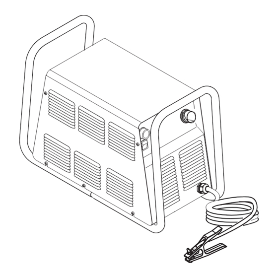
Control Panel Torch Leads Receptacle Art # A-03578 Work Cable and Clamp Gas Pressure Regulator / Filter Assembly CPC Connector for Thermal Dynamics CNC Controller Gas Inlet Port Knockout for Alternate CNC Controller Wire Harness Gas Pressure Gauge Art # A-04214... -
Page 20: Power Supply Options And Accessories
2.05 Power Supply Options and Accessories Section 6, Parts Lists, provides catalog numbers and ordering information. A. Single-Stage Air Filter Kit For use with compressed air shop systems. Filters moisture and particulate matter from the air stream to at least 0.85 microns. This filter increases performance and improves consumables parts life. -
Page 21: Torch Specifications
35' / 10.6 m, with ATC Connector 50' / 15.2 m, with ATC Connector Plasma Power Supply Used With: Thermal Dynamics CutMaster 51, CutMaster 81, CutMaster 101, CutMaster 151 NOTE Torch duty cycle is greater than power supply duty cycle. -
Page 22: Torch Options And Accessories
B. Torch Connector Dimensions 8.5" / 216 mm 5.375" / 137 mm 1.9" / 50 mm Art # A-04056 C. Torch Parts Start Cartridge, Electrode, Tip, Shield Cup Body, Shield Cap D. Parts - In - Place (PIP) Torch Head has built - in switch 12 vdc circuit rating E. -
Page 23: Introduction To Plasma
2.08 Introduction to Plasma A. Plasma Gas Flow Plasma is a gas which has been heated to an extremely high temperature and ionized so that it becomes electrically conductive. The plasma arc cutting and gouging processes use this plasma to transfer an electrical arc to the workpiece. The metal to be cut or removed is melted by the heat of the arc and then blown away. - Page 24 D. Main Cutting Arc DC power is also used for the main cutting arc. The negative output is connected to the torch electrode through the torch lead. The positive output is connected to the workpiece via the work cable and to the torch through a pilot wire.
-
Page 25: Section 3: Installation
SECTION 3: INSTALLATION 3.01 Unpacking 1. Use the packing lists to identify and account for each item. 2. Inspect each item for possible shipping damage. If damage is evident, contact your distributor and / or shipping company before proceeding with the installation. 3. -
Page 26: Primary Input Power Connections
3.03 Primary Input Power Connections CAUTION Check your power source for correct voltage before plugging in or connecting the unit. The primary power source, fuse, and any extension cords used must conform to local electrical code and the recommended circuit protection and wiring requirements as specified in Section 2.03. - Page 27 C. Connections to 460-Volt Single- Phase Power The 460-Volt Power Supply will accept 460-VAC, Single-Phase input power with a change of input power cable. Remove the Power Supply cover per section 5.09-A. 2. Disconnect the original input power cable from the main input contactor and the chassis ground connection. Loosen the through-hole protector on the back panel of the power supply.
-
Page 28: Gas Connections
3.04 Gas Connections A. Connecting Gas Supply to Unit Use only compressed air with this power supply. An in-line pneumatic dryer & evaporator type air filter, capable of filtering to at least 5 microns, is required when using air from a compressor. - Page 29 B. Installing Optional Single-Stage Air Filter A Single-Stage filter kit is recommended for improved filtering, to keep moisture and debris out of the torch. 1. Attach the Single-Stage Filter Hose to the Inlet Port. 2. Attach the Filter Assembly to the filter hose. 3.
- Page 30 C. Installing Optional Two-Stage Air Filter Kit This optional two-stage air line filter is also for use on compressed air shop systems. Filter removes moisture and contami- nants to at least 5 microns. Connect the air supply as follows: a. Attach the Two Stage Filter bracket to the back of the power supply per instructions supplied with the filter assembly.
- Page 31 D. Using High Pressure Air Cylinders When using high pressure air cylinders as the air supply: 1. Refer to the manufacturer’s specifications for installation and maintenance procedures for high pressure regula- tors. 2. Examine the cylinder valves to be sure they are clean and free of oil, grease or any foreign material. Briefly open each cylinder valve to blow out any dust which may be present.
-
Page 32: Torch Connections
3.05 Torch Connections If necessary, connect the torch to the Power Supply. Connect only the Thermal Dynamics model SL100 Torch (with ATC connector) to this power supply. Maximum torch leads length is 50 feet / 15.2 m. WARNING Disconnect primary power at the source before connecting the torch. - Page 33 B. Check Air Quality To test the quality of air: Put the ON / OFF switch in the ON (up) position. Put the RUN / RAPID AUTO RESTART / SET switch in the SET (down) position. Place a welding filter lens in front of the torch and turn on the air. Any oil or moisture in the air will be visible on the lens. Do not start an arc! A-03690 Manual 0-4640...
-
Page 34: Torch Installation
3.06 Torch Installation WARNING Disconnect primary power at the source before disassembling the torch or torch leads. The machine torch includes a positioning tube with rack and pinch block assembly. 1. Mount the torch assembly on the cutting table. 2. To obtain a clean vertical cut, use a square to align the torch perpendicular to the surface of the workpiece. Pinch Block Assembly Square... -
Page 35: Torch Parts Selection
3.07 Torch Parts Selection Check the torch for proper consumable parts. The parts supplied in the torch may not be correct for the operator's chosen amperage level. The torch parts must correspond with the type of operation. Art # A-04173 Torch Head Electrode Start Cartridge... -
Page 36: Power Supply Connection To Sc-11 Standoff Control
The power supply includes an Automation Interface PC Board connected to a CPC connector on the power supply rear panel. For connection to the Thermal Dynamics SC-11 Standoff Control, align and connect the cable from the Standoff Control to the CPC connector. -
Page 37: Power Supply Connection To Alternate Standoff Control
Carefully open the lower knockout (below the factory-installed CNC connector) on the Power Supply rear panel. Knockout for Alternate CNC Controller CPC Connector for Thermal Dynamics CNC Controller Art # A-04178 Install a through-hole protector ('Strain Relief') in the lower knockout hole. - Page 38 Connect the wire harness from the alternate CNC Control to the 20-position terminal strip (labeled 'J2') on the Automation Interface PC Board. Refer to the illustration. a. For divided voltage output, connect to terminals J2-11 (negative) and J2-9 (positive). b. For raw arc voltage, connect to Main Power PC Board terminals E24 (negative) and E27 (positive). Refer to the illustration on the next page.
- Page 39 Main PC Board Main PC Board E24 (-) Connection Points for Raw Arc Voltage E27 (+) TORCH Art # A-04392 Raw Arc Voltage Connection Points Manual 0-4640 3-15 INSTALLATION...
-
Page 40: Automation Interface Pc Board Set-Up
The Automation Interface PC board includes switches that must be set to adapt the Interface Board to the automation system being used. The switches are factory-set for the Thermal Dynamics SC-11 Standoff Control and require no adjustment. For operation with any other CNC equipment, refer to the CNC system documents to determine the division factor the CNC system requires. -
Page 41: Optional Remote Current Control Harness Installation
3.11 Optional Remote Current Control Harness Installation Locate the power supply Pot/LED Board just inside the power supply front panel. Pot / LED Board Art # A-03964 Disconnect and remove the wire harness between the Pot/LED Board and receptacle J22 on the Main PC Board. Keep the harness for possible future use. - Page 42 This Page Left Blank INSTALLATION 3-18 Manual 0-4640...
-
Page 43: Section 4: Operation
SECTION 4: OPERATION 4.01 Product Features A. Power Supply Front Panel Controls and Indicators AC Indicator Steady light indicates power supply is ready for operation. Blinking light indicates unit is in pro- A) Output Current Control tective interlock mode. Shut unit off, shut off or Sets the desired output current. -
Page 44: Preparations For Operating
Power Supply (40 amps maximum). B. Torch Connection Check that the torch is properly connected. Only Thermal Dynamics model SL100 Torches may be connected to this Power Supply. C. Check Primary Input Power Source 1. - Page 45 F. Power On Place the Power Supply ON / OFF switch to the ON (up) position. AC indicator turns on. Gas indicator turns on if there is sufficient gas pressure for power supply operation. NOTE Minimum pressure for power supply operation is lower than minimum for torch operation. A-03746 Manual 0-4640 OPERATION...
- Page 46 G. Set Operating Pressure Place the Power Supply RUN / Rapid Auto Restart / SET switch to the SET (down) position. Gas will flow. A-03690 Adjust gas pressure per the settings chart. 65 - 70 psi / 4.5 - 4.8 bar Pressure Control Knob CutMaster 51 Gas Pressure Settings...
- Page 47 H. Select Current Output Level Place RUN / Rapid Auto Restart / SET to RUN (up) or Rapid Auto Restart (center) position. Gas flow stops. Set the current output level, up to 40 amps. A-03747 Cutting Operation When the torch leaves the workpiece during cutting operations with the RUN / Rapid Auto Restart / SET switch in the RUN (up) position, there is a brief delay in restarting the pilot arc.
-
Page 48: Selection, Inspection And Replacement Of Consumable Torch Parts
4.03 Selection, Inspection and Replacement of Consumable Torch Parts The type of operation to be done determines the torch parts to be used. Change the torch parts for a different operation as follows: WARNINGS Disconnect primary power to the system before disassembling the torch or torch leads. DO NOT touch any internal torch parts while the AC indicator light of the Power Supply is ON. - Page 49 2. Remove the tip. Check for excessive wear (indicated by an elongated or oversized orifice). Clean or replace the tip if necessary. Worn Tip Good Tip A-03406 Tip Wear 3. Remove the start cartridge. Check for excessive wear, plugged gas holes, or discoloration. Check the lower end fitting for free motion.
-
Page 50: Cut Quality
4.04 Cut Quality NOTES Cut quality depends heavily on setup and parameters such as torch standoff, alignment with the workpiece, cutting speed, gas pressures, and operator ability. Cut quality requirements differ depending on application. For instance, nitride build - up and bevel angle may be major factors when the surface will be welded after cutting. -
Page 51: General Cutting Information
4.05 General Cutting Information WARNINGS Disconnect primary power at the source before disassembling the power supply, torch, or torch leads. Frequently review the Important Safety Precautions at the front of this manual. Be sure the operator is equipped with proper gloves, clothing, eye and ear protection. Make sure no part of the operator’s body comes into contact with the workpiece while the torch is activated. -
Page 52: Torch Operation
E. Dross When dross is present on carbon steel, it is commonly referred to as either “high speed, slow speed, or top dross”. Dross present on top of the plate is normally caused by too great a torch to plate distance. “Top dross” is nor- mally very easy to remove and can often be wiped off with a welding glove. - Page 53 B. Travel Speed Proper travel speed is indicated by the trail of the arc which is seen below the plate. The arc can be one of the following: Straight Arc A straight arc is perpendicular to the workpiece surface. This arc is generally recommended for the best cut using air plasma on stainless or aluminum.
-
Page 54: Cutting Parameters
C. Piercing With Machine Torch To pierce with a machine torch, the arc should be started with the torch positioned as high as possible above the plate while allowing the arc to transfer and pierce. This standoff helps avoid having molten metal blow back onto the front end of the torch. -
Page 55: Cutting Specifications
4.08 Cutting Specifications Cut Quality on Various Materials and Torch Specifications For Thicknesses CutMaster 51 Power Supplies Cutting Range The following table defines the cut quality on various mate- Material Mild Steel rials and thicknesses: Genuine Cut: Up to 1/2 inch - 12.7 mm Cut Quality on Various Materials Speed 12-14 ipm / 0.3 - 0.36 mpm... -
Page 56: Cutting Speed Chart: Mild Steel, Sl100 Torch With Exposed Tip
4.09 Cutting Speed Chart: Mild Steel, SL100 Torch with Exposed Tip Art # A-04203 Electrode Start Cartridge Shield Cup Body Shield Cap, Deflector 9-8215 9-8213 9-8237 9-8243 Material: Mild Steel Table: Dry Torch: SL100 with Exposed Tip and Deflector Gas: Compressed Air Power Supply: CutMaster 51 Automated Plasma Pierce... -
Page 57: Cutting Speed Charts: Stainless Steel, Sl100 Torch With Exposed Tip
4.10 Cutting Speed Charts: Stainless Steel, SL100 Torch with Exposed Tip Art # A-04203 Electrode Start Cartridge Shield Cup Body Shield Cap, Deflector 9-8215 9-8213 9-8237 9-8243 Material: Stainless Steel Torch: SL100 with Exposed Tip and Deflector Table: Dry Power Supply: CutMaster 51 Automated Gas: Compressed Air Current Plasma Pierce... -
Page 58: Cutting Speed Charts: Aluminum, Sl100 Torch With Exposed Tip
4.11 Cutting Speed Charts: Aluminum, SL100 Torch with Exposed Tip Art # A-04203 Electrode Start Cartridge Shield Cup Body Shield Cap, Deflector 9-8215 9-8213 9-8237 9-8243 Material: Aluminum Torch: SL100 with Exposed Tip Table: Dry Power Supply: CutMaster 51 Automated Gas: Compressed Air Plasma Pierce... -
Page 59: Cutting Speed Charts: Mild Steel, Sl100 Torch With Shielded Tip
4.12 Cutting Speed Charts: Mild Steel, SL100 Torch with Shielded Tip Electrode Start Cartridge Shield Cup Body Shield Cap, Machine 9-8215 9-8213 9-8237 Art # A-04204 Material: Mild Steel Torch: SL100 with Shielded Tip Table: Dry Power Supply: CutMaster 51 Automated Gas: Compressed Air Torch Shield... -
Page 60: Cutting Speed Charts: Stainless Steel, Sl100 Torch With Shielded Tip
4.13 Cutting Speed Charts: Stainless Steel, SL100 Torch with Shielded Tip Electrode Start Cartridge Shield Cup Body Shield Cap, Machine 9-8215 9-8213 9-8237 Art # A-04204 Material: Stainless Steel Torch: SL100 with Shielded Tip Table: Dry Power Supply: CutMaster 51 Automated Gas: Compressed Air Torch Shield... -
Page 61: Cutting Speed Charts: Aluminum, Sl100 Torch With Shielded Tip
4.14 Cutting Speed Charts: Aluminum, SL100 Torch with Shielded Tip Electrode Start Cartridge Shield Cup Body Shield Cap, Machine 9-8215 9-8213 9-8237 Art # A-04204 Material: Aluminum Torch: SL100 with Shielded Tip Table: Dry Power Supply: CutMaster 51 Automated Gas: Compressed Air Torch Shield Plasma... - Page 62 4.15 Operator's Custom Cutting Speed Charts Art # A-04381 Shield Cap, Machine Shield Cap, Deflector Electrode Start Cartridge Shield Cup Body 9-8243 9-8215 9-8213 9-8237 Material: Torch: SL100 with Shielded Tip Table: Dry Power Supply: CutMaster 51 Automated Gas: Compressed Air Torch Shield Plasma...
-
Page 63: Operator's Custom Cutting Speed Charts
Operator's Custom Cutting Speed Charts Art # A-04381 Shield Cap, Machine Shield Cap, Deflector Electrode Start Cartridge Shield Cup Body 9-8243 9-8215 9-8213 9-8237 Material: Torch: SL100 with Shielded Tip Table: Dry Power Supply: CutMaster 51 Automated Gas: Compressed Air Torch Shield Plasma... -
Page 64: Operator's Custom Cutting Speed Charts
Operator's Custom Cutting Speed Charts Art # A-04381 Shield Cap, Machine Shield Cap, Deflector Electrode Start Cartridge Shield Cup Body 9-8243 9-8215 9-8213 9-8237 Material: Torch: SL100 with Shielded Tip Table: Dry Power Supply: CutMaster 51 Automated Gas: Compressed Air Torch Shield Plasma... -
Page 65: Service
SECTION 5: SERVICE 5.01 General Maintenance A . Filter Element Replacement The Regulator/Filter Assembly is on the rear panel. For better system performance, the Regulator/Filter Assembly filter element should be checked per the Maintenance Schedule in the Appendix section, and either cleaned or replaced. 1. - Page 66 B. Single-Stage Filter Element Replacement These instructions apply to power supplies where the Single-Stage Filter has been installed. The Power Supply shuts down automatically when the Filter Element becomes completely saturated. The Filter Element can be removed from its housing, dried, and reused. Allow 24 hours for Element to dry. 1.
- Page 67 C. Optional Two-Stage Filter Element Replacement The Two-Stage Air Filter has two Filter Elements. When the Filter Elements become dirty the Power Supply will continue to operate but cut quality may become unacceptable. Refer to Section 6, Parts List, for replacement filter element catalog number. 1.
- Page 68 D. Cleaning Torch Even if precautions are taken to use only clean air with a torch, eventually the inside of the torch becomes coated with residue. This buildup can affect the pilot arc initiation and the overall cut quality of the torch. WARNINGS Disconnect primary power to the system before disassembling the torch or torch leads.
-
Page 69: Common Faults
Cutting speed too slow b. Torch standoff too high from workpiece c. Worn torch parts d. Improper cutting current e. Non - Genuine Thermal Dynamics parts used Incorrect gas pressure 4. Short Torch Parts Life a. Oil or moisture in air source b. -
Page 70: Basic Troubleshooting
5.03 Basic Troubleshooting WARNING There are extremely dangerous voltage and power levels present inside this unit. Do not attempt to diagnose or repair unless you have had training in power electronics measurement and troubleshooting techniques. A. Basic Troubleshooting: Overview This guide covers basic troubleshooting. It is helpful for solving many of the common problems that can arise with this system. Follow all instructions as listed and complete each section in the order presented. - Page 71 6. Unit internal fuse blown or loose a. If blown, double-check input voltage and replace fuse. 7. Actual input voltage does not correspond to voltage of unit a. Verify that the input line voltage is correct. Refer to Section 2, Input Wiring Requirements. B.
- Page 72 G. . Torch will not pilot; no gas flow; AC indicator ON, GAS indicator ON, DC indicator 1. Start cartridge missing from torch a. Shut off power supply. Remove shield cup, install start cartridge. Reinstall torch tip and shield cup. Turn power supply ON / OFF switch to ON (up).
- Page 73 Torch cannot be activated; AC indicator flashing; Gas indicator ON; Temp indicator OFF; DC indica- 1. System is in protective interlock mode. (Torch switch in CNC Controller in ON position while turning on power supply ON / OFF switch.) a. Release torch switch. 2.
- Page 74 M . Arc shuts off during operation; arc will not restart when torch switch is activated. 1. Power Supply is overheated (TEMP indicator a. Let unit cool down for at least 5 minutes. Make sure the unit has not been operated beyond Duty Cycle limit. Refer to Section 2 for duty cycle specifications.
-
Page 75: Advanced Troubleshooting Guide - General Information
5.04 Advanced Troubleshooting Guide - General Information WARNING There are extremely dangerous voltage and power levels present inside this unit. Do not attempt to diagnose or repair unless you have had training in power electronics measurement and troubleshooting techniques. A. General Information This Section covers advanced troubleshooting, which requires power supply disassembly and live measurements. - Page 76 C. Main Input and Internal Power Tests 1. Connect main AC power to the unit. 2. Set the Power Supply ON/OFF switch to ON (up) and note the following: • AC indicator steady ON • Gas solenoid energizes (clicks) • Main PCB Relay energizes, pulling in main input contactor (W1) •...
-
Page 77: Main Input And Internal Power Problems
5.05 Main Input and Internal Power Problems A. Opening Power Supply Enclosure The cover of the Power Supply must be removed for access to input power connections and test points. WARNING Disconnect primary power at the source before assembling or disassembling the Power Supply, torch parts, or torch and leads assemblies. - Page 78 Locate your symptom below: A. Main power line fuses blow as soon as main disconnect is closed 1. Input power cable installed incorrectly or defective power cord. a. Refer to Subsection 5.11-I and check that the input power cable is not defective or installed incorrectly. 2.
- Page 79 TP18 Fuse TP10 (F1) Output Diode IGBT TP14 TP13 Art #A-03751 Main Printed Circuit Board Layout D. AC and TEMP indicators ON, fan does not run 1. Air flow through unit is restricted a. Provide adequate air flow 2. Exceeded Duty Cycle of Power Supply a.
- Page 80 Faulty Temperature Sensor / Switch a. Shut input power off. Check IGBT Heatsink Temp Sensor (TS1). Disconnect wire connector P2 from terminal J2 on Main PC Board. Check connector pins 1 and 2 for 10K ohm (±25%) (at ambient temperature). If resistance is not 10K ohm (±25%), replace TS1.
- Page 81 G . Gas continues to flow with RUN / RAPID AUTO RESTART / SET switch in RUN position. 1. Damaged gas solenoid. a. Turn the front panel ON/OFF switch to OFF. • If gas continues to flow, debris from the air line is preventing the solenoid from closing. Clean or replace the solenoid. 2.
- Page 82 3. Faulty Logic PCB. a. Measure for approximately 12 vdc between P1-7 and TP-1 on the Logic PCB. • If 0 vdc is present, replace Logic PCB. P1-1 to P1-36 P1-7 TP10 Art # A-03883 Logic Board Layout SERVICE 5-18 Manual 0-4640...
- Page 83 H. Gas flows continuously when power is turned on; AC indicator flashes 1. Torch switch is activated (closed) before user turns power on a. Release torch switch. 2. Faulty torch switch a. Check torch switch for continuity. Gas cycles on and off when power is turned on; AC indicator flashes 1.
-
Page 84: Pilot Arc Problems
5.06 Pilot Arc Problems WARNING The following tests must be performed with the power supply connected to primary input power. There are extremely dangerous voltage and power levels present inside this unit. Do not attempt to diagnose or repair without proper training in power electronics measurement and troubleshooting techniques. - Page 85 C. Torch will not pilot; AC , GAS , and TEMP indicators ON, DC indicator OFF 1. Air flow blocked a. Check for blocked air flow around the unit and correct condition. 2. Unit is overheated a. Let unit cool down for at least 5 minutes. Make sure the unit has not been operated beyond Duty Cycle limit. Refer to duty cycle data in Specifications Section.
- Page 86 D. Torch will not pilot when torch switch is activated; AC and GAS indicators ON; Temp indicators OFF 1. Gas pressure too high or too low a. Adjust gas pressure per pressure setting label on power supply. 2. Torch tip, start cartridge, or electrode missing. a.
- Page 87 F. Gas flows; No arc in torch; AC , GAS , and DC indicators ON; TEMP indicator 1. Faulty IGBT a. Measure between the following points on the Main PC Board: • E4 to E10 • E10 to E20 Voltage should be approximately 20 vdc before the start signal is active. If voltage measures greater than 100 vdc when the start signal is active, replace the IGBT.
- Page 88 G. No arc or intermittent arc in torch; Gas flows; AC , GAS , and DC indicators ON; TEMP indicator 1. Gas pressure set incorrectly (too high) a. Reset gas pressure per pressure setting label on power supply. 2. Oil/moisture in air lines a.
-
Page 89: Main Arc Problems
5.07 Main Arc Problems Locate your symptom below: A. Main cutting arc will not start 1. Work cable not connected. a. Connect work cable. B. No cutting output 1. Torch not properly connected to power supply a. Check that torch leads are properly attached to power supply 2. - Page 90 P1-1 to P1-36 P1-7 TP10 Art # A-03883 Logic Board Layout SERVICE 5-26 Manual 0-4640...
-
Page 91: Test Procedures
7. Faulty Main Input Contactor. a. Check per Subsection 5.08-D. B. When operating the amperage drops off after the main cutting arc starts. 1. Faulty Pilot Board a. With power off and wires E58 and E62 disconnected from the pilot board, measure for continuity between terminals #E58 and #E62. - Page 92 B. Diode Testing Basics WARNING Disconnect primary power at the source before disassembling the power supply, torch, or torch leads. Testing of diode modules requires a digital volt/ohmmeter that has a diode test scale. Remember that even if the diode module checks good, it may still be bad.
- Page 93 C. Diode Module Board Tests WARNING Disconnect primary power at the source before taking any resistance checks. 1. Input Diode Test a. Disconnect input AC power. b. Check Input Diode for shorted input diode. With an ohmmeter set on the diode range make the following checks from Main PC Board to Input Diode: For 400-Volt and 460-Volt Power Supplies: Meter (+) Meter (-) Indication...
- Page 94 2. Output Diode Module Board Circuit Test a. Use an ohmmeter set on the diode function and make the following measurements on the Output Diode Module Boards to Power Output PC Board. CutMaster 51 Output Diode Test Readings Meter (+) Meter (-) Indication Diode Drop Open...
- Page 95 D. Main Input Power Test WARNING The following tests must be performed with the power supply connected to primary input power. There are extremely dangerous voltage and power levels present inside this unit. Do not attempt to diagnose or repair without proper training in power electronics measurement and troubleshooting techniques.
- Page 96 E. Gas Solenoid Circuit Test Make the following voltage checks and replace the faulty part as required. 1. Place the RUN / RAPID AUTO RESTART / SET Switch to the SET position. 2. Measure for 28 VAC across Solenoid wires #7 and #8. Refer to System Schematic in Appendix Section. •...
- Page 97 2. Output Diode Circuit Test WARNING Disconnect primary power at the source before taking any resistance checks. a. Use an ohmmeter set to the diode function and make the following measurements on the Output Diode Board to Main Power PC Board. CutMaster 51 Output Diode Test Readings Meter (+) Meter (-)
- Page 98 4. Gate Drive & DC Sensing a. After checking all previous steps in Subsection 4.09-G, jumper TP1 to TP3 on the Logic PCB. b. Disconnect wires from the Main PC Board as shown in the chart. When the unit is turned on, the DC light should remain ON. Main PC Board Wire Disconnection Points 208/230V Units E3, E13, E15...
-
Page 99: Major External Parts Replacement
5.09 Major External Parts Replacement WARNING Disconnect primary power to the system before disassembling the torch, leads, or power supply. For replacement of parts not covered in this section, instructions are provided with the replacement part. A. Cover Removal 1. Remove the upper screws which secure the cover to the main assembly. NOTE There is a ground wire connection to the inside of the unit. - Page 100 B. Tube Handle Replacement 1. Remove the power supply cover. 2. Remove the four bolts and star washers securing the tube handles to the base of the unit. 3. Move the input power cable, torch leads and work cable inside the handle, then lift the base of the unit away from the Tube Handle.
-
Page 101: Front Panel Parts Replacement
5.10 Front Panel Parts Replacement WARNING Disconnect input power at the source and bleed down the system before attempting these procedures. A . Current (A) Control Knob Replacement 1. Turn the control knob fully clockwise and note the location of the pointer on the knob. 2. - Page 102 C. RUN / RAPID AUTO RESTART / SET Switch (SW2) Replacement 1. Remove the power supply cover, 2. Disconnect the wires on the rear of the Switch. Note the location of each wire, as shown: Top clip Wire #46 Wire #26 Wire #25 Art # A-03906 3.
-
Page 103: Left Side Internal Parts Replacement
5.11 Left Side Internal Parts Replacement A. Fuse (F1) Replacement 1. Remove the power supply cover, 2. Locate the internal fuse on the left side of the center chassis. 3. Replace the fuse. A replacement fuse is located inside the power supply. Refer to Section 6, Parts Lists, for replacement fuse catalog number. - Page 104 C. Main Input Contactor (W1) Replacement 1. Remove the power supply cover. 2. Label all wires connected to the Input Contactor. 3. Disconnect wires to the Input Contactor from the input cable. 4. Disconnect all other wires connected to the Input Contactor. 5.
- Page 105 D. Logic PC Board Replacement Follow the antistatic procedures provided with the replacement part. 1. Remove the power supply cover. 2. Unlock the two tabs on the card guides protruding from the Main PC Board. Push in the silver part of the tab until the black part pops out on the other side.
- Page 106 10. Install modules as follows: a. Put the replacement module in position, and secure with the screw removed previously. Ensure that the washer is under the head of the screw. Heatsink Main PCB Round Thermal Pad Diode or IGBT Tape Screw Washer Art # A-03907...
- Page 107 F. Input Diode Replacement WARNINGS Follow the electrostatic discharge instructions included with the component to prevent damage to the component. Thermal pads and the large flat surface on the back of diodes must be kept clean. Thermal pads must not be allowed to pick up any foreign material.
- Page 108 8. Install module as follows: a. Put the replacement module in position, and secure with the replacement screws. Ensure that the washers are under the heads of the screws. b. Torque the screws to 35 in-lb / 3.95 Nm. CAUTION Failure to torque properly will cause component damage.
- Page 109 G. Main PC Board Replacement Follow the antistatic procedures provided with the replacement part. 1. Remove the power supply cover. 2. Remove the Logic PC Board. 3. Remove the POT/LED PC Board. 4. Disconnect all wire and cable connections to the Main PC Board, including the connections from the three smaller PC Boards.
- Page 110 Input Power Cable Replacement 1. Remove the power supply cover. 2. Locate and label the input power cable connections and disconnect the cable. 3. Remove the hardware securing the input power ground wire to the ground stud on the base of the power supply. 4.
-
Page 111: Right Side Internal Parts Replacement
5.12 Right Side Internal Parts Replacement A. Fan (M1) Replacement 1. Remove the power supply cover. 2. Remove the two screws securing the Fan to the Fan Shroud and let the Fan drop down. 3. Turn the Fan slightly and slide the Fan out, left side first. 4. - Page 112 C. Main Transformer (T5) Replacement The Main Transformer is located behind the Fan Shroud. For access to the Main Transformer, remove the Solenoid/Pressure Switch Assembly and the Fan and Fan Shroud. 1. Remove the power supply cover. 2. Release the tabs on the side and top of the Fan Shroud securing the Solenoid/Pressure Switch Assembly in position, enabling the Assembly to move freely.
- Page 113 D. Output Inductor Assembly (L1) Replacement 1. Remove the power supply cover. 2. Disconnect the two wires connected to terminals E5 and E10 located on the right side of the Main Power PC Board. Pull through the bottom hole in the Center Chassis. 3.
-
Page 114: Rear Panel Parts Replacement
5.13 Rear Panel Parts Replacement A. Filter/Regulator Assembly Replacement WARNING Disconnect the gas supply at the source and bleed down the system before performing this procedure. 1. Disconnect the gas input hose from the Filter/Regulator Assembly on the Rear Panel of the power supply. 2. -
Page 115: Parts Lists
SECTION 6: PARTS LISTS 6.01 Introduction A. Parts List Breakdown The parts list provide a breakdown of all replaceable components. The parts lists are arranged as follows: Section 6.03 Complete Power Supply Replacements Section 6.04 Power Supply Options & Accessories Section 6.05 Power Supply Major External Replacement Parts Section 6.06 Power Supply Front Panel Replacement Parts Section 6.07 Power Supply Left Side Internal Replacement Parts... -
Page 116: Power Supply Options And Accessories
6.04 Power Supply Options and Accessories Description Catalog # Single-Stage Filter Kit (includes Filter & Hose) 7-7507 Replacement Filter Body 9-7740 Replacement Filter Hose (not shown) 9-7742 Replacement Filter Element 9-7741 Two-Stage Filter Kit (includes Hose & Mounting Screws) 7-7500 Bracket, Filter Mounting (not shown) 9-7535 Two-Stage Air Filter Assembly... -
Page 117: Power Supply Major External Replacement Parts
6.05 Power Supply Major External Replacement Parts Item # Description Catalog # Cover with labels 9-7999 Tube, roll handle 9-8320 Hardware: Screw, 10-32 x 1/2 PPH Swageform See Note 1 Washer, 1/4 External Star See Note 1 Screw, 1/4 - 20 x 3/4" Hex See Note 1 Art # A-02819 Manual 0-4640... -
Page 118: Front Panel Replacement Parts
6.06 Front Panel Replacement Parts Item # Description Catalog # Knob, Fluted, Skirted, 0.250 I.D. 9-8527 On/Off Rocker Switch 8-3258 Run/Rapid Auto Restart / Set Switch 8-3259 Assembly, Pot/LED PCB 9-8004 Cable, Work, #6 awg with Clamp, 20 Ft (6.1 m) 9-8528 Art # A-02850 PARTS LISTS... - Page 119 This Page Left Blank Manual 0-4640 PARTS LISTS...
-
Page 120: Left Side Internal Replacement Parts
6.07 Left Side Internal Replacement Parts Item # Description Catalog # Fuse 1/2A, 250V (For 208/230-Volt units) 9-8110 1/2A, 600V (For 400-Volt and 460-Volt units) 9-8583 Main Input Contactor For 208/230-Volt Units 9-8522 For 400-Volt and 460-Volt Units 9-8554 PCB Kit, Input Diode 9-7088 Input Diode Thermal Pad... - Page 121 Center Chassis Input Diode Mounting Plate (part of Center Chassis) Art # A-03904 Manual 0-4640 PARTS LISTS...
-
Page 122: Rear Panel Replacement Parts
6.08 Rear Panel Replacement Parts Item # Description Catalog # Assembly, Filter/Regulator 9-7514 Regulator/Filter Replacement Element 9-4414 Regulator Mounting Bracket 9-7589 Input Power Cable For 208/230-Volt Units 8-4384 For 400-Volt Units (non-CE) 9-8562 For 400-Volt CE Units 9-8553 For 460-Volt Units 9-8593 Mounting Nut 9-5804... - Page 123 This Page Left Blank Manual 0-4640 PARTS LISTS...
-
Page 124: Right Side Internal Replacement Parts
6.09 Right Side Internal Replacement Parts Item # Description Catalog # Assembly, Pressure Switch/Solenoid SOL1, PS1 9-8329 Assembly, Pilot PCB 9-7985 Fan, 220V, 115 CFM 9-7687 Assembly, Main Transformer 9-8544 Assembly, Output Inductor 9-8560 Automation Interface PC Board 9-4894 Automation Interface Wire Harness 9-4895 Transformer (only in power supplies connected to SL100SV Torch 9-9449... - Page 125 A, B Heatsink Art # A-07119 NOTE Illustration may vary slightly from unit. Manual 0-4640 6-11 PARTS LISTS...
-
Page 126: Torch Replacement Parts
6.10 Torch Replacement Parts SL100 Torch, without Solenoid Assembly Item No. Qty Description Catalog No. Torch Head Assembly without leads (includes items 2, 3, and 14) 9-8220 Large O - Ring 8-3487 Small O - Ring 8-3486 PIP Switch Kit 9-7036 PIP Plunger and Return Spring Kit 9-7045... - Page 127 Art # A-03872 Manual 0-4640 6-13 PARTS LISTS...
- Page 128 6.11 Torch Replacement Parts SL100SV Torch, with Solenoid Assembly Item No. Qty Description Catalog No. Torch Head Assembly without leads (includes items 2, 3, and 14) 9-8220 Large O - Ring 8-3487 Small O - Ring 8-3486 PIP Switch Kit 9-7036 PIP Plunger and Return Spring Kit 9-7045...
- Page 129 Art # A-07113 Manual 0-4640 6-15 PARTS LISTS...
-
Page 130: Torch Consumables
6.12 Torch Consumables The illustration shows all consumable parts for the SL100 torch. The Shield Cup Body with the Deflector Shield Cap provides extended parts life and improved resistance to reflected heat. The electrode and starter cartridge are the same for all operations. 6.13 Torch Spare Parts Kits Description Catalog #... -
Page 131: Complete Torch Assembly Replacement
6.14 Complete Torch Assembly Replacement Description Catalog # 100 - Amp Machine Torch and Leads Assemblies, Unshielded Leads, without Solenoid: SL100 Machine Torch and 5 foot / 1.5 m Leads, with ATC Connector 7-5213 SL100 Machine Torch and 10 foot / 3.05 m Leads, with ATC Connector 7-5214 SL100 Machine Torch and 25 foot / 7.6 m Leads, with ATC Connector 7-5215... - Page 132 This Page Left Blank PARTS LISTS 6-18 Manual 0-4640...
-
Page 133: Appendix 1: Sequence Of Operation (Block Diagram
APPENDIX 1: SEQUENCE OF OPERATION (BLOCK DIAGRAM) ACTION: ACTION: ACTION: ACTION: RUN / ON / OFF switch to ON Close external RUN / Rapid Auto Restart / SET disconnect switch. Rapid Auto Restart / RESULT: switch to RUN SET switch RESULT: AC indicator to SET... -
Page 134: Appendix 2: Data Tag Information
APPENDIX 2: DATA TAG INFORMATION West Lebanon, NH USA 03784 Manufacturer's Name and/or Logo, Location, Model and Revision Level, Serial Number Model: and Production Code Date of Mfr: Made in USA Type of Power Regulatory Standard Covering Supply (Note 1) This Type of Power Supply Output Current Type Duty Cycle Factor... -
Page 135: Appendix 3: Maintenance Schedule
APPENDIX 3: MAINTENANCE SCHEDULE This schedule applies to all types of non-liquid cooled plasma cutting systems. Some systems will not have all the parts listed and those checks need not be performed. NOTE The actual frequency of maintenance may need to be adjusted according to the operating environment. Daily Operational Checks or Every Six Cutting Hours: 1. -
Page 136: Appendix 4: Torch Pin - Out Diagrams
APPENDIX 4: TORCH PIN - OUT DIAGRAMS A. Power Supply and SL100 Torch (without Solenoid) ATC Male Connector - ATC Female Receptacle - Front View Front View Negative / Plasma Negative / Plasma 4 - Not Used 8 - Open 8 - Open 4- Open 7 - Green /... -
Page 137: Appendix 5: Torch Connection Diagrams
APPENDIX 5: TORCH CONNECTION DIAGRAMS A. Power Supply and SL100 Torch (without Solenoid) Automated CutMaster Power Supply with ATC Torch Receptacle, Automated SL100 Torch with ATC Connector, ATC Female ATC Male Torch Receptacle Torch Leads Connector Power Supply Torch Head Torch Leads Socket Pin No.s... -
Page 138: Appendix 6: Control Cable Pin - Out Diagram
APPENDIX 6: CONTROL CABLE PIN - OUT DIAGRAM 2 / White Alignment Spline 3 / Red / Torch Switch 1 / Black 6 / Blue / (Positive) SC-11 Controller 5 / Orange (Negative) SC-11 Controller 4 / Green / Torch Switch 7 / Yellow / Arc Volts (Negative) 10 / Violet 9 / Brown / Arc Volts (Positive) -
Page 139: Appendix 7: Interface Pcb Switch Settings (Most Common Settings
Volts Out SW 4 Division Factor 100vdc In 200vdc In 0 = DOWN = OFF, 1 = UP = ON Factory Default Settings Suitable for Thermal Dynamics SC-11 Standoff Control: 6.00 12.00 16.3:1 Other Common Settings: 5.00 10.00 20:1 30:1... -
Page 140: Appendix 8: Interface Pcb Switch Settings (Division Factors 16-24
APPENDIX 8: INTERFACE PCB SWITCH SETTINGS (Division Factors 16-24) Automation Interface Switch Setting Chart - Division Factors 16 - 24 Switch 1 Switch 2 Switch 3 Switch 4 Switch 5 Switch 6 Switch 7 Switch 8 Divide Factor 0 = DOWN = OFF, 1 = UP = ON 16.56 16.70... -
Page 141: Appendix 9: Interface Pcb Switch Settings (Division Factors 24-30
APPENDIX 9: INTERFACE PCB SWITCH SETTINGS (Division Factors 24-30) Automation Interface Switch Setting Chart, Division Factors 24-30 Switch 1 Switch 2 Switch 3 Switch 4 Switch 5 Switch 6 Switch 7 Switch 8 Divide Factor 0 = DOWN = OFF, 1 = UP = ON 24.22 24.36... -
Page 142: Appendix 10: Interface Pcb Switch Settings (Division Factors 30-33
APPENDIX 10: INTERFACE PCB SWITCH SETTINGS (Division Factors 30-33) Automation Interface Switch Setting Chart, Division Factors 30-33 Switch 1 Switch 2 Switch 3 Switch 4 Switch 5 Switch 6 Switch 7 Switch 8 Divide Factor 0 = DOWN = OFF, 1 = UP = ON 30.01 30.03... -
Page 143: Appendix 11: Interface Pcb Switch Settings (Division Factors 33-36
APPENDIX 11: INTERFACE PCB SWITCH SETTINGS (Division Factors 33-36) Automation Interface Switch Setting Chart, Division Factors 33 - 36 Switch 1 Switch 2 Switch 3 Switch 4 Switch 5 Switch 6 Switch 7 Switch 8 Divide Factor 0 = DOWN = OFF, 1 = UP = ON 33.01 33.04... -
Page 144: Appendix 12: Interface Pcb Switch Settings (Division Factors 36-43
APPENDIX 12: INTERFACE PCB SWITCH SETTINGS (Division Factors 36-43) Automation Interface Switch Setting Chart, Division Factors 36-43 Switch 1 Switch 2 Switch 3 Switch 4 Switch 5 Switch 6 Switch 7 Switch 8 Divide Factor 0 = DOWN = OFF, 1 = UP = ON 36.03 36.16... -
Page 145: Appendix 13: Interface Pcb Switch Settings (Division Factors 43-50
APPENDIX 13: INTERFACE PCB SWITCH SETTINGS (Division Factors 43-50) Automation Interface Switch Setting Chart, Division Factors 43 - 50 Switch 1 Switch 2 Switch 3 Switch 4 Switch 5 Switch 6 Switch 7 Switch 8 Divide Factor 0 = DOWN = OFF, 1 = UP = ON 43.04 43.19... -
Page 146: Appendix 14: Automation Interface Pc Board Wiring Layout
APPENDIX 14: AUTOMATION INTERFACE PC BOARD WIRING LAYOUT Rear Panel Pilot Board Automation Interface Automation Interface PC Board CPC Connector PCB Connector J4 To Chassis Ground on Right Side of Power Supply Chassis 8 7 6 5 4 3 2 1 Automation Interface To Ground Stud PCB Connector J1... - Page 147 APPENDIX 15: AUTOMATION INTERFACE PC BOARD LAYOUT and TEST POINTS Art # A-03903 Signals Connector J2 (To wiring harness for alternate Connector J4 (to CPC Connector on Power Supply Rear Panel) CNC Controller) J4-1 Arc Volts (-) (Through 100K ohm resistor) J2-1 Torch Switch (Positive) J4-2...
-
Page 148: Appendix 16: Automation Interface Pc Board Wiring Connections To Oem Cnc Harness
APPENDIX 16: AUTOMATION INTERFACE PC BOARD WIRING CONNECTIONS TO OEM CNC HARNESS 10 11 15 16 Terminal Block J4 To Main PC Board Terminal J27-3 To Main PC Board Terminal J27-2 To Main PC Board Terminal J27-1 Installed only with Optional Remote Current Control Automation Interface PC Board Art # A-04151... -
Page 149: Appendix 17: Automation Interface Pc Board Wiring Connections To Alternate Cnc Harness
APPENDIX 17: AUTOMATION INTERFACE PC BOARD WIRING CONNECTIONS TO ALTERNATE CNC HARNESS Terminal Block J2 To Main PC Board Terminal J27-3 To Main PC Board Terminal J27-2 To Main PC Board Terminal J27-1 Installed only with Optional Remote Current Control Automation Interface PC Board Art # A-04150 Manual 0-4640... -
Page 150: Appendix 18: Main Pc Board Layout
APPENDIX 18: MAIN PC BOARD LAYOUT TP18 Fuse TP10 (F1) Output Diode IGBT TP14 TP13 Connection Points for Raw Arc Voltage Art #A-04391 Main Power PC Board Signals J1-1 +12vdc to Logic PCB J1-15 Logic Low = CSR Signal to Logic PCB J1-16 Ground Signal J1-2... - Page 151 J1-29 Gate Drive A from Logic PCB J1-30 Negative out J21-1 Gate Drive A Return J1-31 Current Sense J21-2 Gate Drive A J1-32 Current Sense J1-33 Current Sense Return J22-1 Pot High J1-34 Current Sense Return J22-2 Pot Wiper J1-35 I Sense J22-3 Pot Low...
-
Page 152: Appendix 19: Main Pc Board Wiring Layout (208 /230-Volt Power Supplies
APPENDIX 19: MAIN PC BOARD WIRING LAYOUT (208 /230-Volt POWER SUPPLIES) Copper To IGBT Heatsink To ON/OFF Switch Solenoid / Pressure Switch Strap Temp Sensor and Mode Switch To Chassis Contactor Harness Test To Inductor Ground Connection (Open) Temp Switch Fuse Logic Board Connector (J1) -
Page 153: Appendix 20: Main Pc Board Wiring Layout (400-Volt And 460-Volt Power Supplies
APPENDIX 20: MAIN PC BOARD WIRING LAYOUT (400-Volt and 460-Volt POWER SUPPLIES) To IGBT Heatsink To ON/OFF Switch Solenoid / Pressure Switch Temp Sensor and Mode Switch To Chassis Contactor Harness Test To Inductor Ground Connection (Open) Temp Switch Fuse Logic Board Connector (J1) To POT/LED PCB... -
Page 154: Appendix 21: Logic Board Layout
APPENDIX 21: LOGIC BOARD LAYOUT P1-1 to P1-36 P1-7 TP10 Art # A-03883 APPENDIX A-22 Manual 0-4640... - Page 155 Logic Board Signals P1-26 Gate Drive B Return P1-27 Gate Drive B Signal P1-1 +12vdc from Main PCB P1-28 Gate Drive A Return P1-2 +12vdc from Main PCB P1-29 Gate Drive A Signal P1-3 Ground P1-30 (-) Output Signal P1-4 Ground P1-31 Current Sense Signal...
-
Page 156: Appendix 22: Pot / Led Board Layout
APPENDIX 22: POT / LED BOARD LAYOUT A-03712 Pot/LED PC Board Signals J14-1 from Main PC Board (J27-1) Pot High J14-2 Main PC Board (J27-2) Pot Wiper J14-3 from Main PC Board (J27-3) Pot Low J14-4 12vdc (J27-4) J14-5 Logic Low Signal for AC OK Indicator from Logic PC Board (J27-5) J14-6 Logic Low Signal for GAS Indicator from Logic PC Board (J27-6) J14-7... -
Page 157: Appendix 23: Output Diode Board Layout
APPENDIX 23: OUTPUT DIODE BOARD LAYOUT A-02853 Manual 0-4640 A-25 APPENDIX... -
Page 158: Appendix 24: Pilot Board Layout
APPENDIX 24: PILOT BOARD LAYOUT Art # A-04221 Pilot Board Signals J1-1 +12 vdc to Automation Interface PC Board J1-3 J1-2 DC Common to Automation Interface PC Board J1-2 J28-1 +12 vdc J28-2 DC Com J28-3 Not Used J28-4 Not Used J28-5 Logic Low CSR J28-6... -
Page 159: Appendix 25: Input Diode Layout
APPENDIX 25: INPUT DIODE LAYOUT Art # A-03882 Manual 0-4640 A-27 APPENDIX... -
Page 160: Appendix 26: 28Vac Circuit Diagram
APPENDIX 26: 28VAC CIRCUIT DIAGRAM Line Voltage Fuse 3 4 5 6 ON/OFF Switch 1 2 5 6 primary J23 (Test) Auxiliary Transformer Voltage Protection CRT/+12 Regulator +12vdc Main Power PC Board A-03710 APPENDIX A-28 Manual 0-4640... - Page 161 This Page Left Blank Manual 0-4640 A-29 APPENDIX...
-
Page 162: Appendix 27: 208/230V System Schematic
APPENDIX 27: 208/230V SYSTEM SCHEMATIC Power Supply & SL100 Torch (without Solenoid) 208 / 230V INPUT INP UT DIODE A S S Y 19X2073 CHASSIS COPPER STRAP E 14 (FILTERING) F1 (6/10A 600V) FAN1 (0 ohm) 28VAC B 28VAC A 230V GA TE DRIVE A RTN GA TE DRIVE A... - Page 163 603-298-5711 E CO 101429 HAS 0 6 /09/04 D ate: I n f o r m a t i o n P r oprietary to THERMAL DYNAMICS CORPORATION. (E58) 0 5 /27/03 (46) N o t F o r R e l e a s e , Reproduction, or Distribution without Written Consent.
-
Page 164: Appendix 28: 208/230V System Schematic
APPENDIX 28: 208/230V SYSTEM SCHEMATIC Power Supply & SL100SV Torch (with Solenoid) 208 / 230V INPUT INPUT DIODE ASSY 19X2073 COPPER STRAP CHASSIS (FILTERING) F1 (6/10A 600V) (0 ohm) FAN1 28VAC B 28VAC A 230V GATE DRIVE A RTN GATE DRIVE A GATE DRIVE B RTN GATE DRIVE B 28VAC B... - Page 165 (E58) Date: Date: Date: ECO B028 01/09/06 Information Proprietary to THERMAL DYNAMICS CORPORATION. Information Proprietary to THERMAL DYNAMICS CORPORATION. Information Proprietary to THERMAL DYNAMICS CORPORATION. 05/27/03 (46) Not For Release, Reproduction, or Distribution without Written Consent. Not For Release, Reproduction, or Distribution without Written Consent.
-
Page 166: Appendix 29: 400/460V System Schematic
APPENDIX 29: 400/460V SYSTEM SCHEMATIC Power Supply & SL100 Torch (without Solenoid) 400/460V 400/460V ...OR... 1 PHASE 3 PHASE INPUT INPUT (44) INP UT DIODE A S S Y 19X2073 CHASSIS 400V 3 PHASE INPUT (FILTERING) 400V ’CE’ VERSION INCLUDES IN-LINE EMC FILTER F1 (1/4A 500V) R94 (460V) - Page 167 603-298-5711 E CO 101429 HAS 0 6 /09/04 D ate: I n f o r m a t i o n P r oprietary to THERMAL DYNAMICS CORPORATION. (E58) 0 5 /27/03 (46) N o t F o r R e l e a s e , Reproduction, or Distribution without Written Consent.
-
Page 168: Appendix 30: 400/460V System Schematic
APPENDIX 30: 400/460V SYSTEM SCHEMATIC Power Supply & SL100SV Torch (with Solenoid) ...OR... 400/460V 400/460V 1 PHASE 3 PHASE INPUT INPUT (44) INPUT DIODE ASSY 19X2073 400V 3 PHASE INPUT CHASSIS (FILTERING) 400V 'CE' VERSION INCLUDES IN-LINE EMC FILTER F1 (1/4A 500V) R94 (460V) R93 (400V) FAN1... - Page 169 (E58) Date: Date: Date: ECO B028 01/09/06 Information Proprietary to THERMAL DYNAMICS CORPORATION. Information Proprietary to THERMAL DYNAMICS CORPORATION. Information Proprietary to THERMAL DYNAMICS CORPORATION. 05/27/03 (46) Not For Release, Reproduction, or Distribution without Written Consent. Not For Release, Reproduction, or Distribution without Written Consent.
- Page 170 APPENDIX 31: Publication History Publication Date* Rev. Revisions 1/3/05 Released to production. 2/14/05 Updated per ECO 101610, adding parts to Spare Parts Kits. Feb. 1, 2006 Updated per ECOs B016 (logic boards), B028 (SL100SV torch) and ECR A044 (power supply updates for SL100SV torch [with solenoid on mounting tube]). Added new replacement parts, new wiring diagram, new schematics.
-
Page 171: Global Customer Service Contact Information
GLOBAL CUSTOMER SERVICE CONTACT INFORMATION Thermadyne USA Thermadyne Asia Sdn Bhd 2800 Airport Road Lot 151, Jalan Industri 3/5A Denton, Tx 76207 USA Rawang Integrated Industrial Park - Jln Batu Arang 48000 Rawang Selangor Darul Ehsan Telephone: (940) 566-2000 West Malaysia 800-426-1888 Fax: 800-535-0557 Telephone: 603+ 6092 2988... - Page 172 Corporate Headquarters 16052 Swingley Ridge Road Suite 300 St. Louis, MO 63017 Telephone: 636-728-3000 Email: TDCSales@Thermadyne.com www.thermadyne.com...
Need help?
Do you have a question about the CUTMASTER SL100SV and is the answer not in the manual?
Questions and answers