
Related Manuals for Thermal Dynamics CUTMASTER 151


Summary of Contents for Thermal Dynamics CUTMASTER 151
-
Page 1: Service Manual
™ CUTMASTER PLASMA CUTTING SYSTEM Art # A-06754 Service Manual Rev. AD.01 Date: April 13, 2007 Manual # 0-4669 Operating Features:... - Page 3 Manufacturer assumes no liability for its use. Plasma Cutting Power Supply CutMaster™ 151 Operating Manual Number 0-4669 Covered under U.S. Patents Published by: Thermal Dynamics Corporation 82 Benning Street West Lebanon, New Hampshire, USA 03784 (603) 298-5711 www.thermal-dynamics.com © Copyright 2005, 2006, 2007 by Thermal Dynamics Corporation All rights reserved.
-
Page 5: Table Of Contents
TABLE OF CONTENTS SECTION 1: GENERAL INFORMATION ....................1-1 1.01 Notes, Cautions and Warnings ..............1-1 1.02 Important Safety Precautions ............... 1-1 1.03 Publications ....................1-2 1.04 Note, Attention et Avertissement ..............1-3 1.05 Precautions De Securite Importantes ............1-3 1.06 Documents De Reference ................ - Page 6 TABLE OF CONTENTS (continued) SECTION 6: PARTS LISTS ........................6-1 6.01 Introduction ....................6-1 6.02 Ordering Information ..................6-1 6.03 Major External Replacement Parts ............... 6-2 6.04 Front Panel Replacement Parts ..............6-3 6.05 Left Side Internal Component Replacement Parts ........6-4 6.06 Rear Panel Replacement Parts ..............
-
Page 7: General Information
SECTION 1: GASES AND FUMES GENERAL INFORMATION Gases and fumes produced during the plasma cutting process can be dangerous and hazardous to your health. 1.01 Notes, Cautions and Warnings • Keep all fumes and gases from the breathing area. Throughout this manual, notes, cautions, and warnings Keep your head out of the welding fume plume. -
Page 8: Publications
• Wear dry gloves and clothing. Insulate yourself from the work piece or other parts of the welding PLASMA ARC RAYS circuit. • Repair or replace all worn or damaged parts. Plasma Arc Rays can injure your eyes and burn your skin. •... -
Page 9: Note, Attention Et Avertissement
6. ANSI Standard Z49.2, FIRE PREVENTION IN THE USE ATTENTION OF CUTTING AND WELDING PROCESSES, obtain- able from American National Standards Institute, 1430 Broadway, New York, NY 10018 Toute procédure pouvant résulter l’endommagement du matériel en cas de non- 7. AWS Standard A6.0, WELDING AND CUTTING CON- respect de la procédure en question. - Page 10 • Eloignez toute fumée et gaz de votre zone de respira- • Ne touchez jamais une pièce “sous tension” ou “vive”; tion. Gardez votre tête hors de la plume de fumée portez des gants et des vêtements secs. Isolez-vous provenant du chalumeau. de la pièce de travail ou des autres parties du circuit de soudage.
-
Page 11: Documents De Reference
ultra-violets très forts. Ces rayons d’arc nuiront à vos 1.06 Documents De Reference yeux et brûleront votre peau si vous ne vous protégez pas correctement. Consultez les normes suivantes ou les révisions les plus récentes ayant été faites à celles-ci pour de plus amples •... - Page 12 9. Norme 70 de la NFPA, CODE ELECTRIQUE NA- TIONAL, disponible auprès de la National Fire Pro- tection Association, Batterymarch Park, Quincy, MA 02269 10. Norme 51B de la NFPA, LES PROCÉDÉS DE COUPE ET DE SOUDAGE, disponible auprès de la National Fire Protection Association, Batterymarch Park, Quincy, MA 02269 11.
-
Page 13: Declaration Of Conformity
Rigorous testing is incorporated into the manufacturing process to ensure the manufactured product meets or exceeds all design specifications. Thermal Dynamics has been manufacturing products for more than 30 years, and will continue to achieve excellence in our area of manufacture. -
Page 14: Statement Of Warranty
Thermal Dynamics Corporation will honor warranty claims submitted within the warranty periods listed below. All warranty periods begin on the date of sale of the product to the original retail customer or 1 year after sale to an authorized Thermal Dynamics Distributor. -
Page 15: Introduction
A complete understanding of the capabilities the equipment and peripheral accessories provided by and functions of this equipment will assure obtaining the Thermal Dynamics in good operating order in accordance performance for which it was designed. with the procedures outlined in the operating manual, and to protect the equipment from accidental or malicious The CutMaster™... - Page 16 This Page Left Blank INTRODUCTION Manual 0-4669...
-
Page 17: Description
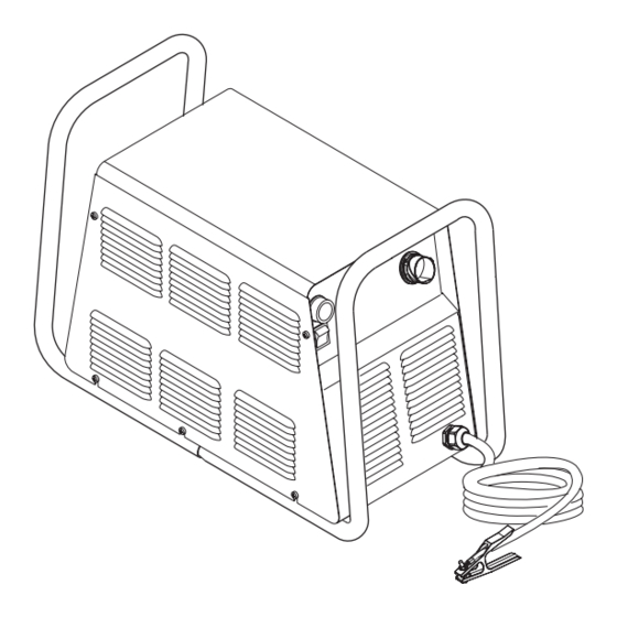
SECTION 3: DESCRIPTION 3.01 Scope The purpose of this section is: • To familiarize the service technician with the capabilities and limitations of the equipment; • To provide an overall understanding which will allow the technician, in turn, to properly train customer operat- ing personnel. - Page 18 Handle and Leads Wrap Control Panel Torch Leads Receptacle Art # A-04507 Work Cable and Clamp Gas Pressure Regulator / Filter Assembly Gas Inlet Port Ports for Optional Automation Interface Cable Gas Pressure Gauge Art # A-03738 Input Power Cord DESCRIPTION Manual 0-4669...
-
Page 19: Air Regulator/Filter Assembly Specifications
3. Dimensions and Weight 83 lb / 37.6 kg 17.3 in / 439 mm 27.5 in / 696 mm 12.4 in / 315 mm A-03572 1. Front Panel Controls and Features • Main Power ON / OFF Switch • RUN /RAPID AUTO RESTART Switch •... - Page 20 This Page Left Blank DESCRIPTION Manual 0-4669...
-
Page 21: Troubleshooting
SECTION 4: 4.03 System Theory TROUBLESHOOTING A. Logic PC Board Functions The Logic PC Board controls the timing and sequenc- ing of the system. It monitors gas pressure and power 4.01 Introduction supply internal temperatures, and controls the gas flow. The Logic Board also controls the safety latch circuit. -
Page 22: Common Operating Problems
Non-Genuine Thermal Dynamics parts used cut is to start. When starting at the edge of the plate, 2. Main Arc Extinguishes do not pause at the edge and force the arc to “reach”... -
Page 23: Troubleshooting Guide - General Information
Section 4.08 - Pilot Arc Problems d. Improper cutting current Section 4.09 - Main Arc Problems e. Non-Genuine Thermal Dynamics parts used Section 4.10 - Test Procedures 4. Short Torch Parts Life Subsection 4.10 includes specific test procedures and in- a. -
Page 24: Circuit Fault Isolation
B. Initial Setup Conditions 4.06 Circuit Fault Isolation This section is to help isolate the defective circuit before A. Controls and Indicators troubleshooting, identify symptoms, and test the unit for proper operation. Follow the instructions as given to iden- tify the possible symptom(s) and the defective circuit. After repairs are complete, run the following tests again to verify that the unit is fully operational. -
Page 25: Main Input And Internal Power Problems
D. Pilot Arc Test 3. Carefully lift the cover off the unit, and remove the nut securing the ground wire to the side panel. 1. Activate the torch (press torch switch on the handle, 4. Re-install the cover by reversing the above steps. send START signal from CNC Control, or press the torch switch on the Remote Pendant) to establish a pilot arc and note the following:... - Page 26 C. Fans do not operate; all control panel indicators OFF 6. Improper input power cable connections inside Power Supply 1. Front Panel ON/OFF switch in OFF position a. Refer to System Schematic and correct if needed. a. Place switch to ON (up) position. 7.
- Page 27 11. Faulty ON/OFF switch 4. Faulty Temperature Sensor / Switch Measure for 28 VAC on the Main PC Board be- a. Shut input power off. Check IGBT Heatsink tween J18-5 to J18-6. Temp Sensor (TS1). Disconnect wire connector P29 from terminal J29 on Main PC Board. Check a.
- Page 28 F. RUN / RAPID AUTO RESTART /SET switch in 2. Faulty Components in Unit RUN or RAPID AUTO RESTART position; AC Measure for 12 vdc from wire #10 to wire #11 at the Gas Pressure Switch, located on the right side of indicator ON;...
- Page 29 G. Gas continues to flow with RUN / RAPID AUTO I. Gas cycles on and off when power is turned on; AC RESTART / SET switch in RUN position. indicator flashes; TEMP indicator off, 1. Damaged gas solenoid. a. Turn the front panel ON/OFF switch to OFF. GAS indicator •...
- Page 30 Fuse Secondary Transformer Logic Board Not Shown IGBT Module Input Diode (mounts to center chassis) IGBT Module IGBT IGBT Art # A-04640 Main Printed Circuit Board Layout, (Logic PCB Not Shown) TROUBLESHOOTING 4-10 Manual 0-4669...
-
Page 31: Pilot Arc Problems
3. Faulty IGBT(s) 4.08 Pilot Arc Problems a. Measure between the following points on the IGBTs: WARNING • IGBT A: E4 to E10 E10 to E20 The following tests must be performed with the power supply connected to primary input power. There •... - Page 32 3. Torch starter cartridge is stuck 4. Faulty Temperature Sensor / Switch a. Turn off power supply. Remove shield cup, tip, CAUTION and starter cartridge. Check lower end fitting Turn off input power for the following tests. on starter cartridge for free movement. Replace cartridge if lower end fitting does not move freely.
-
Page 33: Main Arc Problems
D. Gas flows; AC indicator and GAS indicators b. Place a welding filter lens in front of the torch and turn on the air. Any oil or moisture in the ON; TEMP indicator off; DC indicator air will be visible on the lens. Do not start an arc! off or blinks on/off once. - Page 34 5. Faulty Main Input Contactor. 4.09 Main Arc Problems a. Check per Subsection 4.10-D. Locate your symptom below: B. When operating the amperage drops off after the A. Main cutting arc will not start main cutting arc starts. 1. Work cable not connected. 1.
-
Page 35: Service
SECTION 5: SERVICE 5.01 General Maintenance A. Filter Element Replacement The Regulator/Filter Assembly is on the rear panel. For better system performance, the Regulator/Filter Assembly filter element should be checked regularly, and either cleaned or replaced. 1. Remove power from the power supply; turn off the gas supply and bleed down the system. Turn the regulator adjustment knob to the 'zero' setting. - Page 36 B. Single-Stage Filter Element Replacement The Single-Stage Filter is an option. The Power Supply shuts down automatically when the Filter Element becomes completely saturated. The Filter Element can be removed from its housing, dried, and reused. Allow 24 hours for Element to dry. Refer to Section 6, Parts List, for replacement filter element catalog number.
- Page 37 C. Optional Two-Stage Filter Element Replacement The Two-stage filter is an option. When the Filter Elements become dirty the Power Supply will continue to operate but cut quality may become unacceptable. Refer to Section 6, Parts List, for replacement filter element catalog number. 1.
- Page 38 D. Cleaning Torch Even if precautions are taken to use only clean air with a torch, eventually the inside of the torch becomes coated with residue. This buildup can affect the pilot arc initiation and the overall cut quality of the torch. WARNINGS Disconnect primary power to the system before disassembling the torch or torch leads.
-
Page 39: Power Supply Major External Parts Replacement
5.02 Power Supply Major External Parts Replacement WARNING Disconnect primary power to the system before disassembling the torch, leads, or power supply. For replacement of parts not covered in this section, instructions are provided with the replacement part. A. Cover Removal 1. - Page 40 B. Tube Handle Replacement 1. Remove the power supply cover per Section 5.02-A. 2. Remove the four bolts and star washers securing the tube handles to the base of the unit. 3. Move the input power cable, torch leads and work cable inside the handle, then lift the base of the unit away from the Tube Handle.
-
Page 41: Front Panel Parts Replacement
5.03 Front Panel Parts Replacement WARNING Disconnect input power at the source and bleed down the system before attempting these procedures. A. Current (A) Control Knob Replacement 1. Turn the control knob fully clockwise and note the location of the pointer on the knob. 2. - Page 42 C. RUN / RAPID AUTO RESTART / SET Switch (SW2) Replacement 1. Remove the power supply cover per Section 5.02-A. 2. Disconnect the wires on the rear of the Switch. Note the location of each wire, as shown: Top clip Wire #46 Wire #26 Wire #25...
-
Page 43: Left Side Internal Parts Replacement
5.04 Left Side Internal Parts Replacement A. Fuse (F1) Replacement 1. Remove the power supply cover per Section 5.02-A. 2. Locate the internal fuse on the left side of the center chassis. 3. Replace the fuse. A replacement fuse is located inside the power supply. Refer to Section 6, Parts Lists, for replacement fuse catalog number. - Page 44 B. Main Input Contactor (W1) Replacement 1. Remove the power supply cover per Section 5.02-A. 2. Label all wires connected to the Input Contactor. 3. Disconnect wires to the Input Contactor from the input cable. 4. Disconnect all other wires connected to the Input Contactor. 5.
- Page 45 C. Logic PC Board Replacement Follow the antistatic instructions provided with the replacement part to prevent damage to the component. The Logic PC Board connects to the Main PC Board through an extender board perpendicular to both boards. 1. Remove the power supply cover per Section 5.02-A. 2.
- Page 46 7. The thermal pad, provided with the replacement part, is a thin metal pad. Remove any loose protective paper coverings from the pad. NOTE Protective coverings must be removed from the thermal pads. Installing thermal pads with protective coverings in place will cause equipment damage or failure.
- Page 47 400V 415V Units 208/230V Units 460V 600V Copper Strap Input Input Diode Diode (mounts (mounts to center to center Power Supply Power Supply chassis) chassis) Main PC Board Main PC Board To Input To Input Contactor Art # A-04610 Contactor Input Diode Bridge Wiring, 208/230V Units Input Diode Bridge Wiring, 400-460-600V Units 11.
- Page 48 E. IGBT Replacement Follow the antistatic instructions provided with the replacement part to prevent damage to the component. 1. Note the placement of all wires to the IBGT(s) being replaced. 2. Carefully remove the 3 sets of hardware securing each IGBT PC board being replaced to the IGBT module mounted to the power supply heat sink.
- Page 49 8. Secure replacement IGBT PC Board(s) with the hardware removed previously. Ensure that the washers are under the heads of the screws. IGBT Modules IGBT PC Boards Art # A-04643 9. Torque screws to 22 in-lb. (2.5 Nm). NOTE Failure to torque properly will cause component damage. 10.
- Page 50 E. Main PC Board Replacement Follow the antistatic procedures provided with the replacement part. 1. Remove the power supply cover per Section 5.02-A. 2. Remove the Logic PC Board and the extender board. 3. Remove the POT/LED PC Board. 4. Disconnect all wire and cable connections to the Main PC Board, including the connections from the three smaller PC Boards.
- Page 51 F. Input Power Cable Replacement 1. Remove the power supply cover per Section 5.02-A. 2. Locate and label the input power cable connections and disconnect the cable. Connections to To E2 Main PCB To E3 To E1 Input Side Main Contactor Main Contactor Input Side...
-
Page 52: Rear Panel Parts Replacement
5.05 Rear Panel Parts Replacement WARNING Disconnect primary power from the source before opening or disassembling the power supply. A. Filter/Regulator Assembly Replacement WARNING Disconnect the gas supply at the source and bleed down the system before attempting this procedure. 1. - Page 53 D. Rear Panel Replacement WARNING Disconnect primary input power and the gas supply at the source and bleed down the system before performing this procedure. 1. Remove the cover per subsection 5.02-A. 2. Remove the primary input power cable per section 5.04-F. 3.
-
Page 54: Right Side Internal Parts Replacement
5.06 Right Side Internal Parts Replacement A. Fan Replacement (M1, M2) 1. Remove the power supply cover per Section 5.02-A. 2. Label, then carefully remove the wiring connectors from the terminals on the Fans. 3. Disconnect the Work Cable from terminal E61 on the Power Output Board. 4. - Page 55 C. Pilot PC Board Replacement The Pilot PC Board mounts to the Power Supply center chassis. Refer to Pilot Board Layout in the Appendix. Follow the antistatic instructions provided with the replacement part to prevent damage to the component. 1. Remove the power supply cover per Section 5.02-A. 2.
- Page 56 E. Output Diode PC Board Replacement Follow the antistatic instructions provided with the replacement part to prevent damage to the component. 1. Remove cover per subsection 5.02-A. 2. Locate the Output Diode PCB(s) located within the Output Power PC Board on the right side of the power supply. 3.
- Page 57 Output Diodes Output Power Board Art # A-04645 F. Heatsink Shroud Assembly Removal The Heatsink Shroud Assembly must be disengaged for access to either the Main Transformer or the Output Inductor. Follow these steps for access to either component. 1. Remove the power supply cover per Section 5.02-A. 2.
- Page 58 10. Remove nuts on two studs at the top corners of the Heatsink Shroud, and nuts on two studs on the bottom flange of the Heatsink Shroud. 12. Remove the Heatsink Shroud as follows: a. Use the open left end of the Heatsink Shroud and the Pressure Switch/Solenoid opening as handles. b.
- Page 59 Heatsink Shroud Assembly Replacement 1. Pass transformer wires #45 and 49 through the upper hole in the right (rear) edge of the Heatsink Shroud. Pass trans- former wires #47 and 52 through the lower hole. 2. Route wires as follows: a.
- Page 60 This Page Left Blank SERVICE 5-26 Manual 0-4669...
-
Page 61: Parts Lists
SECTION 6: PARTS LISTS 6.01 Introduction A. Parts List Breakdown The parts lists provide a breakdown of all replaceable components. The parts lists are arranged as follows: Section 6.03 Major External Replacement Parts Section 6.04 Front Panel Replacement Parts Section 6.05 Left Side Internal Component Replacement Parts Section 6.06 Rear Panel Replacement Parts Section 6.07 Right Side Internal Component Replacement Parts Section 6.08 Options and Accessories... -
Page 62: Major External Replacement Parts
6.03 Major External Replacement Parts Item # Description Catalog # Cover with labels 9-8335 Rear Panel (provide data tag information when ordering) For 208/230-Volt Power Supplies Non CSA 9-8323 For 208/230-Volt Power Supplies CSA 9-8668 For 400-Volt, 460-Volt, and 600-Volt Power Supplies 9-8322 Tube, roll handle 9-7998... -
Page 63: Front Panel Replacement Parts
6.04 Front Panel Replacement Parts Item# Description Ref. # Catalog # Knob, Fluted, Skirted 9-8527 On/Off Switch 8-3258 Run / Rapid Auto Restart / Set Switch 8-3259 Assembly, Pot/LED PC Board 9-8004 for (RoHS) 9-0045 Work Cable, #4 AWG, 20 Ft. (6.1 m) with Clamp 9-8336 Art # A-04541 NOTE: Illustration may vary slightly from unit. -
Page 64: Left Side Internal Component Replacement Parts
6.05 Left Side Internal Component Replacement Parts Item # Description Ref # Catalog # Fuse for 208/230-Volt Power Supplies 9-8588 for 400-Volt Power Supplies 9-8602 for 460-Volt Power Supplies 9-8583 for 600-Volt Power Supplies 9-8638 Main Input Contactor for 208/230-Volt Power Supplies 9-8587 for 400-Volt, 460-Volt and 600-Volt Power Supplies 9-8554... - Page 65 Art # A-04514 Manual 0-4669 PARTS LISTS...
-
Page 66: Rear Panel Replacement Parts
6.06 Rear Panel Replacement Parts Item # Description Ref. Catalog # Assembly, Filter/Regulator 9-7514 Regulator/Filter Replacement Element 9-4414 Regulator Mounting Bracket 9-7589 Input Power Cable for 208/230-Volt Units Non CSA 9-8596 for 208/230-Volt Units CSA 9-8665 for 460-Volt and 600-Volt Three-Phase units 9-8593 for 400-Volt Three-Phase units 9-8562... -
Page 67: Right Side Internal Component Replacement Parts
6.07 Right Side Internal Component Replacement Parts Item # Description Ref #. Catalog # Assembly, Pressure Switch/Solenoid Sol1, Ps1 9-8329 Assembly, Pilot Board 9-8337 for (RoHS) 9-0070 Fan, 220V, 115 CFM 9-7687 Assembly, Main Transformer for 208/230-Volt units 9-8345 for 400-Volt units 9-8347 for 460-Volt units 9-8346... -
Page 68: Options And Accessories
6.08 Options and Accessories Description Catalog # Single-Stage Filter Kit (Includes Filter And Hose) 7-7507 Replacement Filter Body 9-7740 Replacement Filter Element 9-7741 Replacement Filter Hose (Not Shown) 9-7742 Two Stage Air Line Filter Kit (Includes Hose & Mounting Screws) 7-7500 Bracket, Filter Mounting (Not Shown) 9-7535... -
Page 69: Patent Information
PATENT INFORMATION The following parts are licensed under U.S. Patent No(s). 5120930 and 5132512 Catalog Number Description 9-8235 Shield Cap, Drag 50-60A 9-8236 Sheild Cap, Drag 70-100A 9-8237 Shield Cup, Body 9-8238 Shield Cap, Machine 50-60A 9-8239 Shield Cap, Machine 70-100A 9-8244 Shield Cap, Drag 40A 9-8245... - Page 70 This Page Left Blank PARTS LISTS 6-10 Manual 0-4669...
-
Page 71: Appendix 1: Input Wiring Requirements
50/60 50/60 21.1 50/60 15.6 Line Voltages with Suggested Circuit Protection and Wire Sizes Based on National Electric Code and Canadian Electrical Code CE CutMaster 151 Input Wiring Specifications Input Power Input Current Input Suggested Sizes (See Notes) Voltage Freq. -
Page 72: Appendix 2: Sequence Of Operation
APPENDIX 2: SEQUENCE OF OPERATION (BLOCK DIAGRAM) ACTION: ACTION: ACTION: ACTION: RUN / ON / OFF switch to ON Close external RUN / Rapid Auto Restart / SET disconnect switch. Rapid Auto Restart / RESULT: switch to RUN SET switch RESULT: AC indicator to SET... -
Page 73: Appendix 3: Logic Pc Board Layout
APPENDIX 3: LOGIC PC BOARD LAYOUT TP10 TP11 Art # A-04641 Logic Board Signals P1-28 Current Sense Return P1-1 +12vdcfrom Main Power PCB P1-29 Current Sense Return P1-2 +12vdcfrom Main PCB P1-30 DC Com P1-31 DC Com P1-3 DC Com P1-32 Not Used P1-4 DC Com... -
Page 74: Appendix 4: Main Power Pc Board Layout
APPENDIX 4: MAIN POWER PC BOARD LAYOUT Fuse Secondary Transformer Logic Board Not Shown IGBT Module Input Diode (mounts to center chassis) IGBT Module IGBT IGBT Art # A-04640 Main Power PC Board Signals J11-1 L1 Input J23-1 Test J11-4 L3 Input J23-2 Test... - Page 75 J43-2 + 12 vdc to Logic PCB J26-1 Gate Drive J43-3 DC Com J26-2 Gate Drive J43-4 DC Com J27-1 Pot High J43-5 MC1 On J27-2 Pot Wiper J43-6 Tip Sense J27-3 Pot Low J43-7 Run / Set J27-4 +12V J43-8 Pressure Good J27-5...
-
Page 76: Appendix 5A: Main Pc Board Wiring Layout - 208/230-Volt Units
APPENDIX 5A: MAIN PC BOARD WIRING LAYOUT - 208/230-Volt Units To Inductor Temp Sensor To Press Switch/Solenoid/Contactor To Power Output Board To Heat Sink Test Connector To On/Off and To Main Temp Sensor Run/Rapid Restart Input Contactor To Torch Set Switches To Chassis Ground To Fans Connector... -
Page 77: Appendix 5B: Main Pc Board Wiring Layout - 400-Volt, 460-Volt, And 600-Volt Units
APPENDIX 5B: MAIN PC BOARD WIRING LAYOUT - 400-Volt, 460-Volt, and 600-Volt Units To Inductor Temp Sensor To Power Output To Press Switch/Solenoid/Contactor Board To Heat Sink To On/Off and Test Temp Sensor To Chassis Run/Rapid Restart Connector Fuse To Torch Ground To Main Set Switches... -
Page 78: Appendix 6: Led/Pot Pc Board Layout
APPENDIX 6: LED/POT PC BOARD LAYOUT A-03712 POT/LED PC Board Signals: J14-1 from Main PC Board (J27-1) Pot High J14-2 Main PC Board (J27-2) Pot Wiper J14-3 from Main PC Board (J27-3) Pot Low J14-4 12vdc (J27-4) J14-5 Logic Low Signal for AC OK Indicator from Logic PC Board (J27-5) J14-6 Logic Low signal for GAS Indicator from Logic PC Board (J27-6) J14-7... -
Page 79: Appendix 7: Igbt Circuit Pc Board Layout
APPENDIX 7: IGBT CIRCUIT PC BOARD LAYOUT Art # A-04569 Manual 0-4669 APPENDIX... -
Page 80: Appendix 8: Output Diode Pc Board Layout
APPENDIX 8: OUTPUT DIODE PC BOARD LAYOUT Art # A-04570 APPENDIX A-10 Manual 0-4669... -
Page 81: Appendix 9: Output Board Wiring Diagram
APPENDIX 9: OUTPUT BOARD WIRING DIAGRAM To Torch To Pilot PCB To Main PCB To Pilot PCB B Output Diodes Chassis Ground A Output Diodes To Output Inductor To Pilot Board To Trans- former To Torch To Trans- former To Output Art # A-04571 Work Cable Inductor... -
Page 82: Appendix 10: Pilot Pc Board Layout
APPENDIX 10: PILOT PC BOARD LAYOUT Connector J28 Connector J1 Art # A-04582 Connector E58 Connector E62 Pilot PC Board Signals J28-1 +12 vdc J28-2 DC Com J28-3 Mode Switch (RAR) Off J28-4 Not Used J28-5 Logic Low CSR J28-6 Not Used J28-7 Not Used... -
Page 83: Appendix 11: 28Vac Circuit Diagram
APPENDIX 11: 28VAC CIRCUIT DIAGRAM Line Voltage Fuse 3 4 5 6 ON/OFF Switch 1 2 5 6 primary J23 (Test) Auxiliary Transformer Voltage Protection CRT/+12 Regulator +12vdc Main Power PC Board A-03710 Manual 0-4669 A-13 APPENDIX... -
Page 84: Appendix 12: Data Tag Information
APPENDIX 12: DATA TAG INFORMATION West Lebanon, NH USA 03784 Manufacturer's Name and/or Logo, Location, Model and Revision Level, Serial Number Model: and Production Code Date of Mfr: Made in USA Type of Power Regulatory Standard Covering Supply (Note 1) This Type of Power Supply Output Current Type Duty Cycle Factor... -
Page 85: Appendix 13: Torch Pin-Out Diagrams
APPENDIX 13: TORCH PIN-OUT DIAGRAMS Hand Torch Pin-out Diagram ATC Female Receptacle ATC Male Connector Front View Front View Negative / Negative / Plasma Plasma 8 - Open 8 - Ground 4 - Green / Switch 4 - Switch 7 - Open 3 - Switch 7 - Open 3 - White /... -
Page 86: Appendix 14: Torch Connection Diagrams
APPENDIX 14: TORCH CONNECTION DIAGRAMS Hand Torch Connection Diagram Torch: SL60 / SL100 Hand Torch Leads: Torch Leads with ATC Connector Power Supply: with ATC Receptacle Male ATC Leads ATC Female Power Connector Receptacle Torch Torch Supply Head Leads Black To Power Supply Switch Circuitry... - Page 87 This Page Left Blank Manual 0-4669 A-17 APPENDIX...
-
Page 88: Appendix 15A: System Schematic (208/230-Volt Units
APPENDIX 15A: SYSTEM SCHEMATIC (208/230-Volt Units) E12A 208/230V 1 PHASE GATE E17A DRIVE INPUT E11A GATE DRIVE E19A (78) INPUT DIODE E21A IGBT BOARD (33) ASSY 19X1787 COPPER STRAP E12B GATE E17B (FILTERING) CHASSIS DRIVE E11B GATE DRIVE (0 ohm) E19B FAN1 (6/10A 600V) - Page 89 RWH 01/27/06 OUTPUT DIODE OUTPUT DIODE Date: Date: Date: Information Proprietary to THERMAL DYNAMICS CORPORATION. Information Proprietary to THERMAL DYNAMICS CORPORATION. Information Proprietary to THERMAL DYNAMICS CORPORATION. ASSEMBLY 19X2213 ASSEMBLY 19X2213 03/03/05 Not For Release, Reproduction, or Distribution without Written Consent.
-
Page 90: Appendix 15B: System Schematic (400 - 460-Volt Units
APPENDIX 15B: SYSTEM SCHEMATIC (400 - 460-Volt Units) E12A GATE E17A DRIVE 208/230V 400/415V 1 PHASE /460V 3 PHASE INPUT INPUT E11A GATE DRIVE E19A INPUT DIODE E21A IGBT BOARD 400V 3 PHASE E12B INPUT GATE E17B (FILTERING) CHASSIS DRIVE 400V 'CE' VERSION INCLUDES IN-LINE EMC FILTER... - Page 91 OUTPUT DIODE Date: Date: Date: ECO B028 12/27/05 Information Proprietary to THERMAL DYNAMICS CORPORATION. Information Proprietary to THERMAL DYNAMICS CORPORATION. Information Proprietary to THERMAL DYNAMICS CORPORATION. ASSEMBLY 19X2213 ASSEMBLY 19X2213 03/03/05 Not For Release, Reproduction, or Distribution without Written Consent.
-
Page 92: Appendix 15C: System Schematic (600-Volt Units
APPENDIX 15C: SYSTEM SCHEMATIC (600-Volt Units) E12A GATE E17A DRIVE 600VAC 3 PHASE INPUT E11A GATE DRIVE E19A INPUT DIODE E21A IGBT BOARD ASSY 19X1787 E12B CHASSIS GATE E17B (FILTERING) DRIVE E11B GATE (0 ohm) DRIVE E19B FAN1 (3/10A 600V) E21B 230V IGBT BOARD... - Page 93 RWH 01/27/06 OUTPUT DIODE OUTPUT DIODE Date: Date: Date: ECO B077 07/31/06 Information Proprietary to THERMAL DYNAMICS CORPORATION. Information Proprietary to THERMAL DYNAMICS CORPORATION. Information Proprietary to THERMAL DYNAMICS CORPORATION. ASSEMBLY 19X2213 ASSEMBLY 19X2213 03/03/05 DC COMMON DC COMMON Not For Release, Reproduction, or Distribution without Written Consent.
-
Page 94: Appendix 16: Publication History
APPENDIX 16: Publication History Date Rev. Comments 3/25/05 Placed on-line, no official ‘release’ done. 6/6/05 Revised – added 400V, 460V, CE units, updated 208/230V replacement rear panel & cord cat no., added 600V IGBT. 6/27/05 Corrected Input Wiring Specs. 7/8/05 Added 230V CSA rear panel and power cords parts per ECO 101731. -
Page 95: Global Customer Service Contact Information
GLOBAL CUSTOMER SERVICE CONTACT INFORMATION Thermadyne USA Thermadyne Asia Sdn Bhd 2800 Airport Road Lot 151, Jalan Industri 3/5A Denton, Tx 76207 USA Rawang Integrated Industrial Park - Jln Batu Arang Telephone: (940) 566-2000 48000 Rawang Selangor Darul Ehsan West Malaysia 800-426-1888 Telephone: 603+ 6092 2988 Fax: 800-535-0557... - Page 96 Corporate Headquarters 16052 Swingley Ridge Road Suite 300 St. Louis, MO 63017 Telephone: 636-728-3000 Email: TDCSales@Thermadyne.com www.thermadyne.com...
Need help?
Do you have a question about the CUTMASTER 151 and is the answer not in the manual?
Questions and answers