Thermal Dynamics Cutmaster Service Manual
20mm
Hide thumbs
Also See for Cutmaster:
- Service manual (128 pages) ,
- Operating manual (84 pages) ,
- Operating manual (82 pages)

Related Manuals for Thermal Dynamics Cutmaster


Summary of Contents for Thermal Dynamics Cutmaster
-
Page 1: Service Manual
20mm CUTMASTER ™ PLASMA CUTTING SYSTEM Art # A-08905_AB Service Manual Rev. AB Date: May 29, 2009 Manual # 0-5079 Operating Features: 380V 400V 415V... - Page 2 1888, or visit us on the web at www.thermal-dynamics.com. This Operating Manual has been designed to instruct you on the correct use and operation of your Thermal Dynamics product. Your satisfaction with this product and its safe operation is our ultimate concern.
- Page 3 While the information contained in this Manual represents the Manufacturer's best judgement, the Manufacturer assumes no liability for its use. Plasma Cutting Power Supply CutMaster™ 20mm SL60 1Torch™ Service Manual Number 0-5079 Published by: Thermal Dynamics Corporation...
- Page 4 This Page Intentionally Blank...
-
Page 5: Table Of Contents
TABLE OF CONTENTS SECTION 1:GENERAL INFORMATION ..................1 1.01 Notes, Cautions and Warnings ..............1 1.02 Important Safety Precautions ................ 1 1.03 Publications....................2 1.04 Note, Attention et Avertissement ..............3 1.05 Precautions De Securite Importantes ............3 1.06 Documents De Reference ................5 1.07 Declaration of Conformity ................ - Page 6 TABLE OF CONTENTS SECTION 5 SYSTEM:SERVICE ....................5-1 5.01 General Maintenance .................5-1 5.02 Maintenance Schedule ................5-2 5.03 Common Faults ...................5-2 5.04 Fault Indicator .....................5-3 5.05 Basic Troubleshooting Guide ..............5-4 5.06 Power Supply Basic Parts Replacement.............5-6 5.07 Circuit Fault Isolation ..................5-8 5.08 Main Input and Internal Power Problems ..........5-12 5.09 Pilot Arc Problems ..................5-16...
- Page 7 TABLE OF CONTENTS APPENDIX 1: SEQUENCE OF OPERATION(BLOCK DIAGRAM) ........A-1 APPENDIX 2: DATA TAG INFORMATION ................A-2 APPENDIX 3: TORCH PIN - OUT DIAGRAMS ..............A-3 APPENDIX 4: TORCH CONNECTION DIAGRAMS ............... A-4 APPENDIX 5: SYSTEM SCHEMATIC, 380/400/415V UNITS ..........A-6 APPENDIX 6: Publication History ...................
- Page 8 TABLE OF CONTENTS...
-
Page 9: Section 1:General Information
CUTMASTER 20mm SECTION 1: • The kinds of fumes and gases from the plasma arc depend on the kind of metal being used, coatings on the metal, and the GENERAL INFORMATION different processes. You must be very careful when cutting... -
Page 10: Publications
CUTMASTER 20mm • Do not cut or weld on containers that may have held combus- 1.03 Publications tibles. Refer to the following standards or their latest revisions for more • Provide a fire watch when working in an area where fire hazards information: may exist. -
Page 11: Note, Attention Et Avertissement
CUTMASTER 20mm 14. American Welding Society Standard AWSF4.1, RECOM- MENDED SAFE PRACTICES FOR THE PREPARATION FOR WELDING AND CUTTING OF CONTAINERS AND PIPING THAT FUMÉE et GAZ HAVE HELD HAZARDOUS SUBSTANCES, obtainable from the La fumée et les gaz produits par le procédé de jet de plasma peuvent American Welding Society, 550 N.W. - Page 12 CUTMASTER 20mm • Utilisez la nuance de lentille qui est suggèrée dans le recommenda- • Montez et maintenez le matériel conformément au Code électrique tion qui suivent ANSI/ASC Z49.1: national des Etats-Unis. (Voir la page 5, article 9.) Nuance Minimum Nuance Suggerée...
-
Page 13: Documents De Reference
CUTMASTER 20mm 1.06 Documents De Reference 14. Norme AWSF4.1 de l’Association Américaine de Soudage, RECOM- MANDATIONS DE PRATIQUES SURES POUR LA PRÉPARATION À Consultez les normes suivantes ou les révisions les plus récentes ayant LA COUPE ET AU SOUDAGE DE CONTENEURS ET TUYAUX AYANT été... -
Page 14: Declaration Of Conformity
Thermal Dynamics has been manufacturing products for more than 30 years, and will continue to achieve excellence in our area of manufacture. -
Page 15: Statement Of Warranty
This warranty is exclusive and in lieu of any warranty of merchantability or fitness for a particular purpose. Thermal Dynamics will repair or replace, at its discretion, any warranted parts or components that fail due to defects in material or workmanship within the time periods set out below. - Page 16 CUTMASTER 20mm This Page Intentionally Blank GENERAL INFORMATION Manual 0-5079...
-
Page 17: Section 2 System:introduction
Electronic copies of this manual can also be downloaded at no charge in Acrobat PDF format by going to the Thermal Dynamics web site listed below and clicking on Thermal Dynamics and then on the Literature link: http://www.thermal-dynamics.com Manual 0-5079... -
Page 18: Power Supply Specifications
20 - 60 Amps, Continuously Adjustable Power Supply Gas Fil- Particulates to 5 Microns tering Ability CutMaster 20mm Power Supply Duty Cycle * Ambient Temperature Duty Cycle Ratings @ 40° C (104° F) Opperating Range 0° - 50° C Rating... -
Page 19: Input Wiring Specifications
CUTMASTER 20mm 2.05 Input Wiring Specifications CutMaster 20mm Power Supply Input Cable Wiring Requirements Input voltage Freq Power Input Suggested Sizes Fuse Flexible Cord Volts I max I eff (amps) (Min. AWG) 50/60 3 Phase 400/415 50/60 Line Voltages with Suggested Circuit Protection and Wire Sizes... -
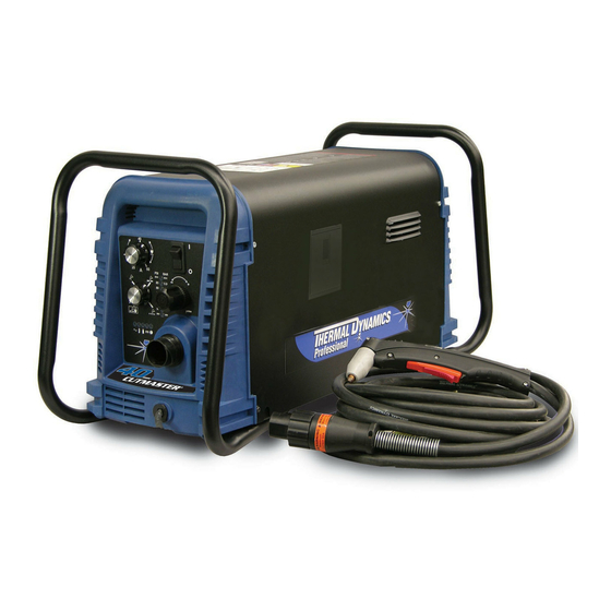
Page 20: Power Supply Features
CUTMASTER 20mm 2.06 Power Supply Features Handle and Leads Wrap Control Panel Torch Leads Receptacle Art # A-07942 Work Cable and Clamp Port for Optional Automation Interface Cable Filter Assembly Gas Inlet Port Art # A-08544 Input Power Cord INTRODUCTION... -
Page 21: Section 2 Torch:introduction
CUTMASTER 20mm SECTION 2 TORCH: 2T.03 Specifications INTRODUCTION A. Torch Configurations 1. Hand/Manual Torch, Models 2T.01 Scope of Manual The hand torch head is at 75° to the torch handle. The hand torches include a torch handle and torch This manual contains descriptions, operating trigger assembly. -
Page 22: 04 Options And Accessories
CUTMASTER 20mm 2T.05 Introduction to Plasma F. Torch Ratings Manual Torch Ratings A. Plasma Gas Flow Ambient 104° F Plasma is a gas which has been heated to an ex- Temperature 40° C tremely high temperature and ionized so that it... - Page 23 CUTMASTER 20mm B. Gas Distribution E. Parts - In - Place (PIP) The single gas used is internally split into plasma The torch includes a 'Parts - In - Place' (PIP) circuit. and secondary gases. When the shield cup is properly installed, it closes a switch.
- Page 24 CUTMASTER 20mm This Page Intentionally Blank INTRODUCTION 2T-4 Manual 0-5079...
-
Page 25: Section 3 System: Installation
CUTMASTER 20mm SECTION 3 SYSTEM: INSTALLATION 3.01 Unpacking 1. Use the packing lists to identify and account for each item. 2. Inspect each item for possible shipping damage. If damage is evident, contact your distributor and / or shipping company before proceeding with the installation. -
Page 26: Primary Input Power Connections
CUTMASTER 20mm 3.03 Primary Input Power Connections CAUTION Check your power source for correct voltage before plugging in or connecting the unit. The primary power source, fuse, and any extension cords used must conform to local electrical code and the recommended circuit protection and wiring requirements as specified in Section 2. - Page 27 CUTMASTER 20mm For CE units: EMC Input Power Filter Art # A-08752_AA • Three phase wires to L1, L2 and L3 on the CE Input Power Filter. It does not matter what order these wires are attached. See previous illustration and on label in the power supply.
-
Page 28: Gas Connections
CUTMASTER 20mm 3.04 Gas Connections Connecting Gas Supply to Unit The connection is the same for compressed air or high pressure cylinders. Refer to the following two subsections if an optional air line filter is to be installed. 1. Connect the air line to the inlet port. The illustration shows typical fittings as an example. - Page 29 CUTMASTER 20mm Installing Optional Single - Stage Air Filter An optional filter kit is recommended for improved filtering with compressed air, to keep moisture and debris out of the torch. 1. Attach the Single - Stage Filter Hose to the Inlet Port.
- Page 30 CUTMASTER 20mm Installing Optional Two - Stage Air Filter Kit This optional two - stage air line filter is also for use on compressed air shop systems. Filter removes moisture and contaminants to at least 5 microns. Connect the air supply as follows: 1.
-
Page 31: Section 3 Torch: Installation
3T.01 Torch Connections 2. Put the Function Control switch in the SET If necessary, connect the torch to the Power Sup- ply. Connect only the Thermal Dynamics model position. SL60 / Manual or SL100 / Mechanical Torch to 3. Place a welding filter lens in front of the this power supply. - Page 32 CUTMASTER 20mm Pinch Block Assembly Square Workpiece A-02585 Mechanical Torch Set - Up 3. The proper torch parts (shield cup, tip, start cartridge, and electrode) must be installed for the type of operation. Refer to Section 4T.07, Torch Parts Selection for details.
-
Page 33: Section 4 System: Operation
CUTMASTER 20mm SECTION 4 SYSTEM: OPERATION 4.01 Front Panel Controls / Features See Illustration for numbering Identification 1. Output Current Control Sets the desired output current. Output settings up to 60 Amps may be used for drag cutting (with the torch tip contacting the workpiece) or standoff cutting. -
Page 34: Preparations For Operation
Set Operating Pressure Check that the torch is properly connected. Only 1. Place the Power Supply Function Control Thermal Dynamics model SL60 / Manual or SL100 / knob to the SET position. Gas will Mechanical Torches may be connected to this Power Supply. - Page 35 CUTMASTER 20mm Typical Cutting Speeds STANDOFF CutMaster 20mm Gas Pressure Settings Cutting speeds vary according to torch output am- perage, the type of material being cut, and opera- Leads SL60 SL100 tor skill. Refer to Section 4T.08 and following for...
- Page 36 CUTMASTER 20mm This Page Intentionally Blank OPERATION Manual 0-5079...
-
Page 37: Section 4 Torch:operation
CUTMASTER 20mm 2. Remove the Electrode by pulling it straight SECTION 4 TORCH: out of the Torch Head. OPERATION Torch Head 4T.01 Torch Parts Selection Electrode Depending on the type of operation to be done determines the torch parts to be used. -
Page 38: 02 Cut Quality
CUTMASTER 20mm 4T.02 Cut Quality Bottom Dross Buildup Molten material which is not blown out of the cut NOTES area and resolidifies on the plate. Excessive dross Cut quality depends heavily on setup and may require secondary cleanup operations after parameters such as torch standoff, alignment with cutting. -
Page 39: 04 Hand Torch Operation
CUTMASTER 20mm Torch Standoff Dross Improper standoff (the distance between the torch When dross is present on carbon steel, it is com- tip and workpiece) can adversely affect tip life as monly referred to as either “high speed, slow speed, well as shield cup life. - Page 40 CUTMASTER 20mm 2. Depending on the cutting operation, do one Trigger of the following: a. For edge starts, hold the torch perpen- dicular to the workpiece with the front of the tip on the edge of the workpiece at the point where the cut is to start.
- Page 41 CUTMASTER 20mm 6. Slide the trigger release toward the back Shield Cup With Straight Edge of the torch handle while simultaneously The drag shield cup can be used with a non conduc- squeezing the trigger. The pilot arc will tive straight edge to make straight cuts by hand.
- Page 42 CUTMASTER 20mm 6. Bring the torch within transfer distance to Piercing With Hand Torch the work. The main arc will transfer to the 1. The torch can be comfortably held in one work, and the pilot arc will shut off.
-
Page 43: 05 Gouging
CUTMASTER 20mm 4T.05 Gouging Lead Angle The angle between the torch and workpiece depends on the output current setting and torch travel speed. The recommended lead angle is 35°. At a lead angle WARNINGS greater than 45° the molten metal will not be blown... -
Page 44: 06 Mechanized Torch Operation
CUTMASTER 20mm 4T.06 Mechanized Torch Operation For optimum smooth surface quality, the travel speed should be adjusted so that only the leading Cutting With Mechanized Torch edge of the arc column produces the cut. If the travel speed is too slow, a rough cut will be produced as... -
Page 45: 07 Parts Selection For Sl60 Torch Cutting
Tips: Tip Gouging A 9-8225 (40 Amps Max.) NOTE Tip Gouging B 9-8226 (50 - 100 Amps) CutMaster 12mm uses 40A and less CutMaster 20mm uses 60A and less Art # A-08951 Tip Gouging C 9-8227 (60 - 120 Amps) -
Page 46: 08 Recommended Cutting Speeds For Sl60 Torch With Exposed Tip
CUTMASTER 20mm 4T.08 Recommended Cutting Speeds for SL60 Torch With Exposed Tip Type Torch: SL60 With Exposed Tip Type Material: Mild Steel Type Plasma Gas: Air Type Secondary Gas: Single Gas Torch Thickness Output Amperage Speed (Per Minute) Standoff Plasma Gas Press... - Page 47 CUTMASTER 20mm Type Torch: SL60 With Exposed Tip Type Material: Stainless Steel Type Plasma Gas: Air Type Secondary Gas: Single Gas Torch Thickness Output Amperage Speed (Per Minute) Standoff Plasma Gas Press Flow (CFH) Pierce Pierce Height Inches mm (Cat. No.) Volts(VDC)
- Page 48 CUTMASTER 20mm Type Torch: SL60 With Exposed Tip Type Material: Aluminum Type Plasma Gas: Air Type Secondary Gas: Single Gas Torch Thickness Output Amperage Speed (Per Minute) Standoff Plasma Gas Press Flow (CFH) Pierce Pierce Height Inches mm (Cat. No.) Volts(VDC)
-
Page 49: 09 Recommended Cutting Speeds For Sl60 Torch With Shielded Tip
CUTMASTER 20mm 4T.09 Recommended Cutting Speeds for SL60 Torch With Shielded Tip Type Torch: SL60 With Shielded Tip Type Material: Mild Steel Type Plasma Gas: Air Type Secondary Gas: Single Gas Torch Thickness Output Amperage Speed (Per Minute) Standoff Plasma Gas Press... - Page 50 CUTMASTER 20mm Type Torch: SL60 With Shielded Tip Type Material: Mild Steel Type Plasma Gas: Air Type Secondary Gas: Single Gas Torch Thickness Output Amperage Speed (Per Minute) Standoff Plasma Gas Press Flow (CFH) Pierce Pierce Height Inches (Cat. No.) Volts (VDC)
- Page 51 CUTMASTER 20mm NOTES * Gas pressure shown is for torches with leads up to 25’ / 7.6 m long. For 50’ / 15.2 m leads, refer to section 4.02 "Operating Pressure". ** Total flow rate includes plasma and secondary gas flow.
-
Page 52: Patent Information
CUTMASTER 20mm PATENT INFORMATION Plasma Cutting Torch Patents The following parts are covered under U.S. and Foreign Patents as follows: Catalog # Description Patent(s) 9-8215 Electrode US Pat No(s) 6163008; 6987238 Other Pat(s) Pending 9-8213 Cartridge US Pat No(s) 6903301; 6717096; 6936786;... - Page 53 CUTMASTER 20mm Catalog # Description Patent(s) 9-8245 Shield Cap US Pat No(s) 6914211; D496951 Other Pat(s) Pending The following parts are also licensed under U.S. Patent No. 5,120,930 and 5,132,512: Catalog # Description 9-8235 Shield Cap 9-8236 Shield Cap 9-8237...
- Page 54 CUTMASTER 20mm This Page Intentionally Blank OPERATION 4T-18 Manual 0-5079...
-
Page 55: Section 5 System:service
CUTMASTER 20mm SECTION 5 SYSTEM: SERVICE 5.01 General Maintenance Manual 0-5079 SERVICE... -
Page 56: Maintenance Schedule
4. Worn torch parts Daily Operational Checks or Every Six Cutting 5. Cutting current too low. Hours: 6. Non - Genuine Thermal Dynamics parts used Check torch consumable parts, replace if dam- 7. Incorrect gas pressure aged, worn or when cut performance has demi- Main Arc 1. -
Page 57: Fault Indicator
CUTMASTER 20mm 5.04 Fault Indicator Explanation of Faults " UNDER PRESSURE: Indicates that operating pres- At initial power up, two lights will temporarily illu- sure is set too low and power supply output minate for 2-3 seconds to show the version of software power will be disabled. -
Page 58: Basic Troubleshooting Guide
CUTMASTER 20mm 5.05 Basic Troubleshooting Guide WARNING There are extremely dangerous voltage and power levels present inside this unit. Do not attempt to diagnose or repair unless you have had training in power electronics measurement and troubleshooting techniques. Problem - Symptom Possible Cause... - Page 59 CUTMASTER 20mm Problem - Symptom Possible Cause Recommended Action FAULT & 80 PSI 1. Torch shield cup is loose. 1. Tighten shield cup by hand. Do not overtighten. indicators flashing. 2. Torch tip, electrode or starter 2. Turn off power supply. Remove shield cup. Install missing Gas flow is cycling on cartridge missing.
-
Page 60: Power Supply Basic Parts Replacement
CUTMASTER 20mm 5.06 Power Supply Basic Parts C. Filter Element Assembly Replacement Replacement The Filter Element Assembly is in the rear panel. For better system performance, the filter element should be checked per the Maintenance Schedule (Subsection 5.02), and either cleaned or replaced. - Page 61 CUTMASTER 20mm 6. Disconnect the input line from the filter element assembly. Housing 7. Remove the filter element assembly through the rear opening. NOTE Filter If replacing or cleaning just the filter element refer Element (Cat. No. 9-7741) to the following illustration for disassembly.
-
Page 62: Circuit Fault Isolation
CUTMASTER 20mm 5.07 Circuit Fault Isolation Optional Two-Stage Filter Element Replacement The Two-Stage Air Filter has two Filter Elements. When the Filter Elements become dirty the Power Supply will WARNING continue to operate but cut quality may become unac- The following procedures should not be attempted ceptable. - Page 63 3. Adjust the pressure regulator to set the gas pres- sure as specified in charts. Pilot IGBT Test – Section 5.12 F STANDOFF If all of the Pre Power-Up Tests are ok, proceed with CutMaster 20mm Gas Pressure Settings the trouble shooting guide. Leads SL60 SL100...
- Page 64 CUTMASTER 20mm G. Main Arc and Controls Test Turn FUNCTION CONTROL SWITCH to RUN position Connect work Cable to the work piece, Close torch • Solenoid turns off, gas stops flowing (pressure switch (Pendant switch or activate CNC Start) to es- display may increase slightly when gas is not tablish a pilot arc.
- Page 65 CUTMASTER 20mm 9. Open the torch switch 3. Remove jumper from J2. • DC LED turns off Arc shuts off • After 20 second post flow time • OK-TO-MOVE signal off (Meter shows no continuity) • Gas solenoid closes • Gas continues to flow •...
-
Page 66: Main Input And Internal Power Problems
CUTMASTER 20mm 5.08 Main Input and Internal Power C. Gas flows with ON/OFF SWITCH in OFF position Problems 1. Foreign debris has lodged in gas solenoid. A. Primary input line fuse blows as soon as a) Replace gas solenoid. This is a problem caused primary disconnect is closed. - Page 67 CUTMASTER 20mm H. PARTS-IN-PLACE (PIP) FAULT. The FAULT 3. Open or improperly connected ribbon cable to J2 connector on Main PCB 1 Indicator and 70 PSI LED is flashing. a) Inspect connaction and check continuity. Re- 1. Shield Cup loose place if open.
- Page 68 CUTMASTER 20mm START ERROR FAULT. The FAULT 4. Open conductor in torch leads Indicator and 75 PSI LED is flashing. a) Check continuity Start signal is active when SW1 is turned to ON 5. Defective Main PCB position. b) Measure voltage at Main Pcb between J2-2 a) Start can be active for one of the following: to test point GND1 for 12VDC.
- Page 69 CUTMASTER 20mm L. AC LED on, TEMP, GAS, DC LED's are off, P. AC LED on, TEMP LED off, GAS LED on, FAULT Indicator is flashing. Gas does not flow in SET mode using a MIN PRESSURE LED is flashing. Gas is not flowing machine torch with remote solenoid.
-
Page 70: Pilot Arc Problems
CUTMASTER 20mm 5.09 Pilot Arc Problems B. SHORTED TORCH FAULT After torch switch is closed, gas flows for two (2) A. AC LED on, TEMP LED off, GAS LED on. seconds then momentarily shuts off then back Nothing happens when torch switch or... -
Page 71: Main Arc And Controls Problems
CUTMASTER 20mm E. AC LED on, TEMP LED off, GAS LED on, 4. Shorted Torch gas flowing, DC LED on, Fault Indicators a) Disconnect torch from unit. With consumables off, Pilot Arc is intermittent. removed from the torch, Check continuity of torch at ATC, between negative/plasma lead 1. -
Page 72: Cnc Interface Problems
CUTMASTER 20mm F. In RAPID AUTO RESTART mode, with 5.12 Test Procedures torch switch closed, the pilot does not start immediately when the cutting arc A. Main Contactor (W1) Test extinguishes 1. Check continuity between: Defective Logic PCB L1 to T1... - Page 73 CUTMASTER 20mm B. Input Diode Module Test 3. Check continuity between the following points Input relays Indication 1. Using an ohmmeter perform the tests in the chart MTH 2 MTH 6 Open MTH 4 MTH 6 Open Input Diode Module...
- Page 74 CUTMASTER 20mm E. Output Diode Module Test Disconnect transformer wires from Main PCB terminal SEC 1. Using an ohmmeter perform the tests in the chart Output Diode Module Meter (+) Meter (-) Indication SEC 1 WORK 1 Forward Bias SEC 1...
- Page 75 CUTMASTER 20mm Signal Information Many of the signal listed will be low voltage signals that will be in one of two states: +12VDC (High) or 0VDC (Low) with respect to pcb common.. When a signal name is preceded by the “/” mark, it denotes that the signal is an active low.
-
Page 76: Capacitor Pcb Layout & Signals
CUTMASTER 20mm 5.13 Capacitor PCB Layout & Signals MTH8 MTH5 MTH6 MTH1 MTH3 MTH4 MTH2 MTH7 Art # A-08841 *J3 CONNECTOR PINOUT CAPACITOR PCB 2 LAYOUT A. CAPACITOR PCB SIGNALS J1-1 Capacitor bank A+ J1-5 Capacitor bank A- J2-1 Capacitor Bank B+... - Page 77 CUTMASTER 20mm B. CAPACITOR PCB TEST POINTS MTH1,2 Capacitor bank A+ MTH3,4 Capacitor bank A- MTH6,8 Capacitor Bank B+ MTH 5,7 Capacitor Bank B- Manual 0-5079 5-23 SERVICE...
-
Page 78: Logic Pcb Layout & Signals
CUTMASTER 20mm 5.14 Logic PCB Layout & Signals *J1 Pinout Art # A-08504_AB LOGIC PCB LAYOUT A. LOGIC PCB SIGNALS (Same for MAIN PCB J2) Signal Source/Destination J1-1 -VOUT (-) OUTPUT VOLTAGE J1-2 /TIP VOLTS Active high when tip is installed... - Page 79 CUTMASTER 20mm Signal Source/Destination J1-5 J1-6 CUR_SET Current demand signal. Variable 1-4VDC J1-7 /RAR Active low when in Rapid Auto Restart mode J1-8 /INRUSH Active low after inrush time expires J1-9 /W1_ON Active low to enable W1 contactor J1-10 SHDN...
- Page 80 CUTMASTER 20mm B. LOGIC PCB LED INDICATORS NORMAL INDICATION FIRMWARE VERSION ERROR MESSAGE +12VDC MAX PRESSURE Over Pressure 90 PSI Internal Error 85 PSI Shorted torch 80 PSI Tip Missing 75 PSI Start Signal active during power up 70 PSI...
- Page 81 CUTMASTER 20mm This Page Intentionally Blank Manual 0-5079 5-27 SERVICE...
-
Page 82: Main Pcb Layout & Signals
CUTMASTER 20mm 5.15 Main PCB Layout & Signals *J2 PINOUT PRI_4 J4 J3 I_DMD1 PRI_1 GND1 PRI_3 PRI_2 TIP1 SEC1 ELECTRODE1 +48V2 +12V2 -V_OUT1 +48V1 J8 J7 J6 J5 Art # A-08518_AB CHOKE1 SEC2 WORK_1 GND2 +12V1 MAIN PCB LAYOUT A. - Page 83 CUTMASTER 20mm J3-1 /230VAC J12-1 +12VDC J3-2 Common J12-2 /460VAC J12-3 /230VAC J4-1 3.3VDc J4-2 B. LED INDICATORS J4-3 D59 PCR Indicates Pilot IGBT gate signal is on J4-4 Common D78 CSR Indicates cutting arc has been established J4-5 C. MAIN PCB TEST POINTS...
-
Page 84: Main Pcb Wiring Diagram
CUTMASTER 20mm 5.16 Main PCB Wiring Diagram To SW2 To Logic Pcb To SW1 To PCB2 SEC1 SEC1 CHOKE1 SEC2 SEC2 ELEC-1 Work Art # A-08902 Cable To ATC To ATC connector To SOL1 CM52 - Jumper To Automation To Fan... -
Page 85: Section 5 Torch:service
CUTMASTER 20mm SECTION 5 TORCH: It is recommended to apply a very light film of o- ring lubricant (Catalog # 8-4025) to the o-rings on a SERVICE weekly basis. 5T.01 General Maintenance NOTE Upper Groove with Vent Holes Refer to Previous "Section 5 System" for common Must Remain Open and fault indicator descriptions. -
Page 86: 02 Inspection And Replacement Of Consumable Torch Parts
CUTMASTER 20mm 5T.02 Inspection and Replacement 4. Remove the tip. Check for excessive wear (indi- cated by an elongated or oversized orifice). Clean of Consumable Torch Parts or replace the tip if necessary. Good Tip Worn Tip WARNINGS Disconnect primary power to the system before disassembling the torch or torch leads. -
Page 87: Section 6:Parts Lists
The following items are included with the replacement power supply: work cable & clamp, input power cable, gas pressure regulator / filter, and operating manual. Description Catalog # CutMaster 20mm Non CE Power Supply With 380/400415VAC 3 phase, 50/60 Hz input power cable 3-1130-3 CutMaster 20mm CE Power Supply... -
Page 88: Major External Replacement Parts
CUTMASTER 20mm 6.04 Major External Replacement Parts Item # Description Catalog # Cover with labels 9-0221 Base Enclosure Assembly 9-0118 Tube, roll handle 9-0121 Front Panel 9-0227 Rear Panel 9-0101 Art # A-08120 NOTE Illustration may vary slightly from unit. -
Page 89: Front Panel Replacement Parts
CUTMASTER 20mm 6.05 Front Panel Replacement Parts Item# Description Ref. Catalog # Output Current Control and Function Control Knobs 9-8527 Toggle - On/Off Switch 9-0109 Work Cable with Clamp, 20 Ft / 6.1 m 9-0184 Not Shown: Wire harness (from SW1) w/EMI Choke (CE Power Supplies Only) -
Page 90: Left Side Replacement Parts
CUTMASTER 20mm 6.06 Left Side Replacement Parts Item # Description Catalog # Main PCB Assembly PCB1 9-0108 Logic PCB PCB3 9-0107* Center Chassis Molded Plastic 9-0102 Fan, MOT1,MOT2 9-0104 Transformer, Main 9-0106 Inductor, Output 9-0105 Not Shown: Power Cable Strain Relief, for all units... -
Page 91: Right Side Replacement Parts
CUTMASTER 20mm 6.07 Right Side Replacement Parts Item # Description Catalog # Contactor, 4 Pole 9-8587 Solenoid, 12V SOL1 9-0114 Spare Parts Box 7-3267 Spare Parts Box Cover 7-3266 Console Quick Disconnect 9-0161 Regulator, with knob and mounting nut 9-0115*... -
Page 92: Options And Accessories
CUTMASTER 20mm 6.08 Options and Accessories Description Catalog # Single - Stage Filter Kit (includes Filter & Hose) 7-7507 Replacement Filter Body 9-7740 Replacement Filter Hose (not shown) 9-7742 Replacement Filter Element 9-7741 Two - Stage Filter Kit (includes Hose & Mounting Screws... -
Page 93: Replacement Parts For Hand Torch
CUTMASTER 20mm 6.09 Replacement Parts for Hand Torch Item # Description Catalog # Torch Handle Replacement Kit (includes items No. 2 & 3) 9-7030 Trigger Assembly Replacement Kit 9-7034 Handle Screw Kit (5 each, 6-32 x 1/2” cap screw, and wrench) 9-8062 Torch Head Assembly Replacement Kit (includes items No. -
Page 94: Replacement Parts - For Mechanized Torches With Unshielded Leads
CUTMASTER 20mm 6.10 Replacement Parts - for Mechanized Torches with Unshielded Leads Item No. Qty Description Catalog No. Torch Head Assembly without leads (includes items 2, 3, and 14) 9-8220 Large O - Ring 8-3487 Small O - Ring 8-3486... - Page 95 CUTMASTER 20mm A-07994 Manual 0-5079 PARTS LIST...
-
Page 96: Torch Consumable Parts Manual And Mechanized Torches
9-8241 9-8237 Tips: Tip Gouging A 9-8225 (40 Amps Max.) NOTE CutMaster 52 uses 60A and less Tip Gouging B 9-8226 (50 - 100 Amps) CutMaster 82 uses 80A and less CutMaster 102 uses 100A and less Art # A-08065_AC... -
Page 97: Section 7: Replacement Procedures
This section describes parts replacement procedures 3. Attach the copper foil to a convenient and ex- which may be performed on the CutMaster 20mm posed electrical ground. Power Supply. 4. Connect the equipment primary cable ground to Under no circumstances are field repairs to be attempted the same electrical ground as the wrist strap. -
Page 98: Major External Parts
CUTMASTER 20mm 7.04 Major External Parts C. Tube Handle Replacement Tools required: T20 Torx Driver A. Cover Removal 1. Disconnect the Torch and Leads from the unit. Tools required: T20 Torx Driver 2. Remove the cover per subsection 7.04 A. -
Page 99: Front Panel Parts Replacement
CUTMASTER 20mm 7.05 Front Panel Parts Replacement D. Air Regulator Replacement Tools required: T20 Torx Driver Refer to section 6.05 for Front Panel Replacement Parts and overall detailed drawing. 1. Remove the cover per subsection 7.04A A. Current Control Potentiometer (A) Knob 2. -
Page 100: Left Side Internal Parts Replacement
CUTMASTER 20mm 7.06 Left Side Internal Parts 7. Install the replacement Logic PCB by reversing the above steps. Replacement 8. Reinstall the power supply cover. A. Fan Replacement G. ON/OFF Switch (SW1) Replacement Tools required: T20 Torx Driver Tools required: T20 Torx Driver 1. -
Page 101: Rear Panel Parts Replacement
CUTMASTER 20mm 7.07 Rear Panel Parts Replacement 13. Remove the two screws securing the Main Trans- former to the base. A. Filter Element Assembly Replacement 14. Remove the Main Transformer, carefully guiding all its wires through from the right side of the The Filter Element Assembly is in the rear panel. - Page 102 CUTMASTER 20mm B. Optional Single-Stage Filter Element 5. Remove the fitting from the filter element as- sembly by inserting a 6 mm hex wrench into Replacement the internal hex fitting and turning it counter These instructions apply to power supplies where the clock-wise (left).
-
Page 103: Right Side Internal Parts Replacement
CUTMASTER 20mm 7.08 Right Side Internal Parts Replacement A. Capacitor PCB (PCB2) Replacement Tools required: T20 Torx Driver 1. Remove the Cover per subsection 7.04A 2. Remove the eight screws securing PCB2 to the Main PCB. 3. Install the replacement PCB by reversing the above steps. - Page 104 CUTMASTER 20mm This Page Intentionally Blank PARTS REPLACEMENT Manual 0-5079...
-
Page 105: Appendix 1: Sequence Of Operation(Block Diagram
CUTMASTER 20mm APPENDIX 1: SEQUENCE OF OPERATION (BLOCK DIAGRAM) ACTION: ACTION: ACTION: ACTION: RUN / Rapid Auto Restart / ON / OFF switch to ON Close external RUN / SET / LATCH disconnect switch. Rapid Auto Restart / switch to RUN... -
Page 106: Appendix 2: Data Tag Information
CUTMASTER 20mm APPENDIX 2: DATA TAG INFORMATION West Lebanon, NH USA 03784 Manufacturer's Name and/or Logo, Location, Model and Revision Level, Serial Number Model: and Production Code Date of Mfr: Made in USA Type of Power Regulatory Standard Covering Supply (Note 1) -
Page 107: Appendix 3: Torch Pin - Out Diagrams
CUTMASTER 20mm APPENDIX 3: TORCH PIN - OUT DIAGRAMS A. Hand Torch Pin - Out Diagram ATC Female Receptacle ATC Male Connector Front View Front View Negative / Negative / Plasma Plasma 8 - Open 8 - Ground 4 - Green /... -
Page 108: Appendix 4: Torch Connection Diagrams
CUTMASTER 20mm APPENDIX 4: TORCH CONNECTION DIAGRAMS A. Hand Torch Connection Diagram Torch: SL60 / SL100 Hand Torch Leads: Torch Leads with ATC Connector Power Supply: with ATC Receptacle Male ATC Leads ATC Female Connector Receptacle Power Torch Torch Supply... - Page 109 CUTMASTER 20mm C. Automation Torch Connection Diagram Automated CutMaster Power Supply with ATC Torch Receptacle, Automated SL100SV Torch (w/ Solenoid on Positioning Tube), Torch Lead with ATC Connector ATC Female ATC Male Torch Receptacle Torch Leads Connector Power Supply Torch Head...
-
Page 110: Appendix 5: System Schematic, 380/400/415V Units
CUTMASTER 20mm APPENDIX 5: SYSTEM SCHEMATIC, 380/400/415V UNITS APPENDIX Manual 0-5079... - Page 111 CUTMASTER 20mm Manual 0-5079 APPENDIX...
-
Page 112: Appendix 6: Publication History
CUTMASTER 20mm APPENDIX 6: Publication History Cover Date Rev. Change(s) Jan 9, 2009 Manual released. May 29, 2009 Updated 400V/600V schematic in appendix per ECOB1399 APPENDIX Manual 0-5079... - Page 113 GLOBAL CUSTOMER SERVICE CONTACT Thermadyne Asia Sdn Bhd Thermadyne USA 2800 Airport Road Lot 151, Jalan Industri 3/5A Rawang Integrated Industrial Park - Jln Batu Arang Denton, Tx 76207 USA Telephone: (940) 566-2000 48000 Rawang Selangor Darul Ehsan West Malaysia 800-426-1888 Fax: 800-535-0557 Telephone: 603+ 6092 2988...
- Page 114 Corporate Headquarters 16052 Swingley Ridge Road Suite 300 St. Louis, MO 63017 Telephone: 636-728-3000 Email: TDCSales@Thermadyne.com www.thermadyne.com...
Need help?
Do you have a question about the Cutmaster and is the answer not in the manual?
Questions and answers