Thermal Dynamics CUTMASTER Operating Manual
Plasma cutting system 12mm 20mm 25mm
Hide thumbs
Also See for CUTMASTER:
- Service manual (128 pages) ,
- Operating manual (84 pages) ,
- Operating manual (82 pages)

Related Manuals for Thermal Dynamics CUTMASTER


Summary of Contents for Thermal Dynamics CUTMASTER
- Page 1 12mm 20mm 25mm CUTMASTER ™ PLASMA CUTTING SYSTEM A-08621 Operating Manual Rev. AE Date: March 20, 2012 Manual # 0-5117 Operating Features: 380- 12mm 380- 20mm 380- 25mm...
- Page 2 YOU ARE IN GOOD COMPANY! The Brand of Choice for Contractors and Fabricators Worldwide. Thermal Dynamics is a Global Brand of manual and automation Plasma Cutting Products for Thermadyne Industries Inc. We distinguish ourselves from our competition through market- leading, dependable products that have stood the test of time.
- Page 3 While the information contained in this Manual represents the Manufacturer's best judgement, the Manufacturer assumes no liability for its use. Plasma Cutting Power Supply CutMaster™ 12mm SL60 1Torch™ Operating Manual No.: 0-5117 CutMaster™ 20mm SL60 1Torch™...
-
Page 4: Table Of Contents
TABLE OF CONTENTS SECTION 1: GENERAL INFORMATION .................1-1 1.01 Notes, Cautions and Warnings ..............1-1 1.02 Important Safety Precautions ..............1-1 1.03 Publications ....................1-2 1.04 Note, Attention et Advertissement ..............1-3 1.05 Precautions De Securite Importantes ............1-3 1.06 Documents De Reference ................1-5 1.07 Declaration of Conformity ................1-6 1.08 Statement of Warranty ................1-7... - Page 5 TABLE OF CONTENTS SECTION 5 SYSTEM: SERVICE .....................5-1 5.01 General Maintenance .................5-1 5.02 Maintenance Schedule ................5-2 5.03 Common Faults ..................5-2 5.04 Fault Indicator .....................5-3 5.05 Basic Troubleshooting Guide ..............5-4 5.06 Power Supply Basic Parts Replacement ............5-6 SECTION 5 TORCH: SERVICE .....................5T-1 5T.01 General Maintenance ................5T-1 5T.02...
- Page 6 This page intentionally blank.
-
Page 7: Section 1: General Information
CUTMASTER 12mm, 20mm, 25mm SECTION 1: • Keep all fumes and gases from the breathing area. Keep your head out of the welding fume plume. GENERAL INFORMATION • Use an air-supplied respirator if ventilation is not adequate to remove all fumes and gases. • The kinds of fumes and gases from the plasma arc depend on 1.01 Notes, Cautions and Warnings the kind of metal being used, coatings on the metal, and the different processes. -
Page 8: Publications
CUTMASTER 12mm, 20mm, 25mm • Ventilate all flammable or explosive vapors from the work- 1.03 Publications place. Refer to the following standards or their latest revisions for more • Do not cut or weld on containers that may have held com- information: bustibles. 1. OSHA, SAFETY AND HEALTH STANDARDS, 29CFR 1910, • Provide a fire watch when working in an area where fire hazards may exist. -
Page 9: Note, Attention Et Advertissement
CUTMASTER 12mm, 20mm, 25mm 1.04 Note, Attention et Advertissement Dans ce manuel, les mots “note,” “attention,” et “avertissement” sont FUMÉE et GAZ utilisés pour mettre en relief des informations à caractère important. Ces mises en relief sont classifiées comme suit : La fumée et les gaz produits par le procédé de jet de plasma peuvent présenter des risques et des dangers de santé. NOTE •... - Page 10 CUTMASTER 12mm, 20mm, 25mm BRUIT INCENDIE ET EXPLOSION Le bruit peut provoquer une perte permanente de l’ouïe. Les pro- Les incendies et les explosions peuvent résulter des scories chaudes, cédés de soudage à l’arc de plasma peuvent provoquer des niveaux des étincelles ou de l’arc de plasma. Le procédé à l’arc de plasma sonores supérieurs aux limites normalement acceptables. Vous produit du métal, des étincelles, des scories chaudes pouvant mettre...
-
Page 11: Documents De Reference
CUTMASTER 12mm, 20mm, 25mm 1.06 Documents De Reference Consultez les normes suivantes ou les révisions les plus récentes ayant été faites à celles-ci pour de plus amples renseignements : 14. Norme AWSF4.1 de l’Association Américaine de Soudage, 1. OSHA, NORMES DE SÉCURITÉ DU TRAVAIL ET DE PROTECTION RECOMMANDATIONS DE PRATIQUES SURES POUR LA PRÉ-... -
Page 12: Declaration Of Conformity
* For environments with increased hazard of electrical shock, Power Supplies bearing the 'S' mark conform to EN50192 when used in conjunction with hand torches with exposed cutting tips, if equipped with properly installed standoff guides. * Extensive product design verification is conducted at the manufacturing facility as part of the routine design and manufacturing process. This is to ensure the product is safe, when used according to instructions in this manual and related industry standards, and performs as specified. Rigor- ous testing is incorporated into the manufacturing process to ensure the manufactured product meets or exceeds all design specifications. Thermal Dynamics has been manufacturing products for more than 30 years, and will continue to achieve excellence in our area of manufacture. Manufacturers responsible representative: Steve Ward Operations Director Thermadyne Europe... -
Page 13: Statement Of Warranty
® purchaser that new Thermal Dynamics CUTMASTER™ 1Series plasma cutting systems sold after the effective date of this warranty are free of defects in material and workmanship. Should any failure to conform to this warranty appear within the applicable period stated below, Thermal Dynamics Corporation shall, upon notification thereof and substantiation that the product has been stored operated and maintained in accordance with Thermal Dynamics’ specifications, instructions, recommendations and recognized industry practice, correct such defects by suitable repair or replacement. - Page 14 CUTMASTER 12mm, 20mm, 25mm This Page Intentionally Blank GENERAL INFORMATION Manual 0-5117...
-
Page 15: Section 2 System: Introduction
Electronic copies of this manual can also be downloaded at no charge in Acrobat PDF format by going to the Thermal Dynamics web site listed below and clicking on Thermal Dynamics and then on the Literature link: http://www.thermal-dynamics.com Manual 0-5117... -
Page 16: Power Supply Specifications
Three Phase, 50/60 Hz Three Phase, 50/60 Hz † NOTE: Some CutMaster 12mm models will only operate on 380-400V. Please check your machine before attempting to run on any of the other voltages that are listed above. Power Supply includes... -
Page 17: Input Wiring Specifications
0.57 m 6" 43 lb / 19.5 kg 150 mm Power Supply Dimensions & Weight Ventilation Clearance Requirements 2.05 Input Wiring Specifications CutMaster 12mm Power Supply Input Cable Wiring Requirements Input voltage Freq Power Input Suggested Sizes Flexible Cord Volts... -
Page 18: Power Supply Features
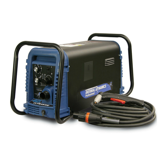
CUTMASTER 12mm, 20mm, 25mm 2.06 Power Supply Features Handle and Leads Wrap Control Panel Torch Leads Receptacle Art # A-07942 Work Cable and Clamp Port for Optional Automation Interface Cable Filter Assembly Gas Inlet Port Art # A-08544 Input Power Cord... -
Page 19: Section 2 Torch: Introduction
CUTMASTER 12, 20, 25mm SECTION 2 TORCH: 2T.03 Specifications INTRODUCTION A. Torch Configurations 1. Hand/Manual Torch, Models 2T.01 Scope of Manual The hand torch head is at 75° to the torch han- dle. The hand torches include a torch handle This manual contains descriptions, operating and torch trigger assembly. -
Page 20: 04 Options And Accessories
CUTMASTER 12, 20, 25mm 2T.05 Introduction to Plasma F. Torch Ratings Manual Torch Ratings A. Plasma Gas Flow Ambient 104° F Plasma is a gas which has been heated to an ex- Temperature 40° C tremely high temperature and ionized so that it... - Page 21 CUTMASTER 12, 20, 25mm B. Gas Distribution E. Parts - In - Place (PIP) The single gas used is internally split into plasma The torch includes a 'Parts - In - Place' (PIP) cir- and secondary gases. cuit. When the shield cup is properly installed, it closes a switch.
- Page 22 CUTMASTER 12, 20, 25mm This Page Intentionally Blank INTRODUCTION 2T-4 Manual 0-5117...
-
Page 23: Section 3 System: Installation
CUTMASTER 12mm, 20mm, 25mm SECTION 3 SYSTEM: 3.03 Primary Input Power Connections INSTALLATION 3.01 Unpacking CAUTION 1. Use the packing lists to identify and ac- Check your power source for correct voltage count for each item. before plugging in or connecting the unit. The 2. -
Page 24: Gas Connections
CUTMASTER 12mm, 20mm, 25mm 3.04 Gas Connections A. Connections to Three Phase Input Power Connecting Gas Supply to Unit WARNING The connection is the same for compressed air or high pressure cylinders. Refer to the follow- Disconnect input power from the power supply ing two subsections if an optional air line filter and input cable before attempting this procedure. - Page 25 CUTMASTER 12mm, 20mm, 25mm Installing Optional Single - Stage Air Filter Installing Optional Two - Stage Air Filter Kit An optional filter kit is recommended for im- This optional two - stage air line filter is also proved filtering with compressed air, to keep for use on compressed air shop systems.
- Page 26 CUTMASTER 12mm, 20mm, 25mm Using High Pressure Air Cylinders When using high pressure air cylinders as the air supply: 1. Refer to the manufacturer’s specifications for installation and maintenance proce- dures for high pressure regulators. 2. Examine the cylinder valves to be sure they are clean and free of oil, grease or any foreign material.
-
Page 27: Section 3 Torch: Installation
2. Put the Function Control switch in the SET If necessary, connect the torch to the Power Sup- position. ply. Connect only the Thermal Dynamics model 3. Place a welding filter lens in front of the SL60 / Manual or SL100 / Mechanical Torch to torch and turn ON the air. - Page 28 CUTMASTER 12mm, 20mm, 25mm Pinch Block Assembly Square Workpiece A-02585 Mechanical Torch Set - Up 3. The proper torch parts (shield cup, tip, start cartridge, and electrode) must be installed for the type of operation. Refer to Section 4T.07, Torch Parts Selection for details.
-
Page 29: Section 4 System: Operation
CUTMASTER 12mm, 20mm, 25mm SECTION 4 SYSTEM: OPERATION 4.01 Front Panel Controls / Features See Illustration for numbering Identification 1. Output Current Control Sets the desired output current. Output settings up to 60 Amps may be used for drag cutting (with the torch tip contacting the workpiece) or higher for standoff cutting. -
Page 30: Preparations For Operation
Set Operating Pressure Check that the torch is properly connected. Only 1. Place the Power Supply Function Control Thermal Dynamics model SL60 / Manual or SL100 / Mechanical Torches may be connected to this knob to the SET position. Gas will Power Supply. - Page 31 CUTMASTER 12mm, 20mm, 25mm Typical Cutting Speeds STANDOFF CutMaster Gas Pressure Settings Cutting speeds vary according to torch output amperage, the type of material being cut, and op- Leads SL60 SL100 erator skill. Refer to Section 4T.08 and following Length...
- Page 32 CUTMASTER 12mm, 20mm, 25mm This Page Intentionally Blank OPERATION Manual 0-5117...
-
Page 33: Section 4 Torch: Operation
CUTMASTER 12mm, 20mm, 25mm SECTION 4 TORCH: 1. Unscrew and remove the shield cup as- sembly from the torch head. OPERATION 2. Remove the Electrode by pulling it straight out of the Torch Head. 4T.01 Torch Parts Selection Torch Head Depending on the type of operation to be done determines the torch parts to be used. -
Page 34: 02 Cut Quality
CUTMASTER 12mm, 20mm, 25mm 4T.02 Cut Quality Bottom Dross Buildup Molten material which is not blown out of the NOTES cut area and resolidifies on the plate. Excessive dross may require secondary cleanup operations Cut quality depends heavily on setup and after cutting. -
Page 35: 04 Hand Torch Operation
CUTMASTER 12mm, 20mm, 25mm 4T.04 Hand Torch Operation Edge Starting For edge starts, hold the torch perpendicular to Standoff Cutting With Hand Torch the workpiece with the front of the tip near (not touching) the edge of the workpiece at the point NOTE where the cut is to start. - Page 36 CUTMASTER 12mm, 20mm, 25mm Trigger Torch Trigger Release Shield Cup Standoff Distance 1/8" - 3/8" (3 - 9mm) Art # A-03383 A-00024_AB 6. Cut as usual. Simply release the trigger Standoff Distance assembly to stop cutting. 3. Hold the torch away from your body.
- Page 37 CUTMASTER 12mm, 20mm, 25mm Shield Cup With Straight Edge The drag shield cup can be used with a non con- ductive straight edge to make straight cuts by hand. Trigger WARNING Trigger Release The straight edge must be non - conduc- A-02986 tive.
-
Page 38: 05 Gouging
CUTMASTER 12mm, 20mm, 25mm 6. Bring the torch within transfer distance to Piercing With Hand Torch the work. The main arc will transfer to the 1. The torch can be comfortably held in one work, and the pilot arc will shut OFF. - Page 39 CUTMASTER 12mm, 20mm, 25mm Torch Head CAUTION Sparks from plasma gouging can cause damage to coated, painted or other sur- faces such as glass, plastic, and metal. 35° Check torch parts. The torch parts must correspond with the type of operation.
-
Page 40: 06 Mechanized Torch Operation
CUTMASTER 12mm, 20mm, 25mm 4T.06 Mechanized Torch Operation For optimum smooth surface quality, the travel Cutting With Mechanized Torch speed should be adjusted so that only the leading edge of the arc column produces the cut. If the The mechanized torch can be activated by remote... -
Page 41: 07 Parts Selection For Manual And Mechanized Torch Cutting
9-8241 9-8237 Tips: Tip Gouging A 9-8225 (40 Amps Max.) NOTE CutMaster 52 uses 60A and less Tip Gouging B 9-8226 (50 - 100 Amps) CutMaster 82 uses 80A and less CutMaster 102 uses 100A and less Art # A-08065_AE... -
Page 42: T.08 Recommended Cutting Speeds For Mechanized Torch With Exposed Tip
CUTMASTER 12mm, 20mm, 25mm 4T.08 Recommended Cutting Speeds for Mechanized Torch With Exposed Type Torch: SL60 With Exposed Tip Type Material: Mild Steel Type Plasma Gas: Air Type Secondary Gas: Single Gas Torch Thickness Output Amperage Speed (Per Minute) Standoff... - Page 43 CUTMASTER 12mm, 20mm, 25mm Type Torch: SL60 With Exposed Tip Type Material: Mild Steel Type Plasma Gas: Air Type Secondary Gas: Single Gas Torch Thickness Output Amperage Speed (Per Minute) Standoff Plasma Gas Press Flow (CFH) Pierce Pierce Height Inches mm (Cat.
- Page 44 CUTMASTER 12mm, 20mm, 25mm Type Torch: SL60 With Exposed Tip Type Material: Mild Steel Type Plasma Gas: Air Type Secondary Gas: Single Gas Torch Thickness Output Amperage Speed (Per Minute) Standoff Plasma Gas Press Flow (CFH) Pierce Pierce Height Inches mm (Cat.
-
Page 45: T.09 Recommended Cutting Speeds For Mechanized Torch With Shielded Tip
CUTMASTER 12mm, 20mm, 25mm 4T.09 Recommended Cutting Speeds for Mechanized Torch With Shielded Type Torch: SL60 With Shielded Tip Type Material: Mild Steel Type Plasma Gas: Air Type Secondary Gas: Single Gas Torch Thickness Output Amperage Speed (Per Minute) Standoff... - Page 46 CUTMASTER 12mm, 20mm, 25mm Type Torch: SL60 With Shielded Tip Type Material: Mild Steel Type Plasma Gas: Air Type Secondary Gas: Single Gas Torch Thickness Output Amperage Speed (Per Minute) Standoff Plasma Gas Press Flow (CFH) Pierce Pierce Height Inches (Cat.
- Page 47 CUTMASTER 12mm, 20mm, 25mm Type Torch: SL60 With Shielded Tip Type Material: Mild Steel Type Plasma Gas: Air Type Secondary Gas: Single Gas Torch Thickness Output Amperage Speed (Per Minute) Standoff Plasma Gas Press Flow (CFH) Pierce Pierce Height Inches mm (Cat. No.) Volts(VDC)
-
Page 48: Patent Information
CUTMASTER 12mm, 20mm, 25mm PATENT INFORMATION Plasma Cutting Torch Patents The following parts are covered under U.S. and Foreign Patents as follows: Catalog # Description Patent(s) 9-8215 Electrode US Pat No(s) 6163008; 6987238 Other Pat(s) Pending 9-8213 Cartridge US Pat No(s) 6903301; 6717096; 6936786;... - Page 49 CUTMASTER 12mm, 20mm, 25mm The following parts are also licensed under U.S. Patent No. 5,120,930 and 5,132,512: Catalog # Description 9-8235 Shield Cap 9-8236 Shield Cap 9-8237 Shield Cup 9-8238 Shield Cap 9-8239 Shield Cap 9-8244 Shield Cap 9-8245 Shield Cap...
- Page 50 CUTMASTER 12mm, 20mm, 25mm This Page Intentionally Blank OPERATION 4T-18 Manual 0-5117...
-
Page 51: Section 5 System: Service
CUTMASTER 12mm, 20mm, 25mm SECTION 5 SYSTEM: SERVICE 5.01 General Maintenance Maintain more often Warning! if used under severe Disconnect input power before maintaining. conditions Each Use Visual check of torch tip and electrode Weekly Visually inspect the cables and leads. -
Page 52: Maintenance Schedule
4. Worn torch parts Daily Operational Checks or Every Six 5. Cutting current too low. Cutting Hours: 6. Non - Genuine Thermal Dynamics parts used 1. Check torch consumable parts, replace if dam- 7. Incorrect gas pressure aged or worn. -
Page 53: Fault Indicator
CUTMASTER 12mm, 20mm, 25mm 5.04 Fault Indicator At initial power up, two lights will temporarily illu- minate for 2-3 seconds to show the version of software used. To determine the first digit, count the function indica- tors left to right, 1 through 5. To determine the second digit count the pressure indicators, reading from bot- tom to top, 0 through 7. -
Page 54: Basic Troubleshooting Guide
CUTMASTER 12mm, 20mm, 25mm 5.05 Basic Troubleshooting Guide WARNING There are extremely dangerous voltage and power levels present inside this unit. Do not attempt to diagnose or repair unless you have had training in power electronics measurement and troubleshooting techniques. - Page 55 CUTMASTER 12mm, 20mm, 25mm Problem - Symptom Possible Cause Recommended Action FAULT & 80 PSI 1. Torch shield cup is loose. 1. Tighten shield cup by hand. Do not overtighten. indicators flashing. 2. Torch tip, electrode or starter 2. Turn OFF power supply. Remove shield cup. Install Gas flow is cycling cartridge missing.
-
Page 56: Power Supply Basic Parts Replacement
CUTMASTER 12mm, 20mm, 25mm 5.06 Power Supply Basic Parts C. Filter Element Assembly Replacement Replacement The Filter Element Assembly is in the rear panel. For better system performance, the filter element should be checked per the Maintenance Schedule (Subsection 5.02), and either cleaned or replaced. - Page 57 CUTMASTER 12mm, 20mm, 25mm Optional Single-Stage Filter Element 5. Remove the fitting from the filter element as- sembly by inserting a 6 mm hex wrench into Replacement the internal hex fitting and turning it counter These instructions apply to power supplies where the clock-wise (left).
- Page 58 CUTMASTER 12mm, 20mm, 25mm Optional Two-Stage Filter Element Replacement The Two-Stage Air Filter has two Filter Elements. When the Filter Elements become dirty the Power Supply will continue to operate but cut quality may become unacceptable. Refer to Section 6, Parts List, for replacement filter element catalog number.
-
Page 59: Section 5 Torch: Service
CUTMASTER 12mm, 20mm, 25mm SECTION 5 TORCH: SERVICE Upper Groove 5T.01 General Maintenance with Vent Holes Must Remain Open NOTE Upper O-Ring in Correct Groove Refer to Previous "Section 5 System" for common and fault indicator descriptions. Threads Cleaning Torch... -
Page 60: 02 Inspection And Replacement Of Consumable Torch Parts
CUTMASTER 12mm, 20mm, 25mm 5T.02 Inspection and Replacement Remove the tip. Check for excessive wear (in- dicated by an elongated or oversized orifice). of Consumable Torch Parts Clean or replace the tip if necessary. Good Tip Worn Tip WARNING Disconnect primary power to the system be- fore disassembling the torch or torch leads. -
Page 61: Section 6: Parts Lists
380/400 VAC 3 phase, 50 Hz with input power cable 3-1130-4 CutMaster 25mm 400V CE Power Supply with 380/400 VAC, 3 Phase, 50 Hz, with input power cable 3-1330-4 CutMaster 25 400V Non CE Power Supply with 400/415VAC, 3 Phase, 50 Hz, with input power cable 3-1130-3 Manual 0-5117... -
Page 62: Replacement Power Supply Parts
CUTMASTER 12mm, 20mm, 25mm 6.04 Replacement Power Supply Parts Description Catalog # Regulator 9-0115* Filter Assembly Replacement Element 9-0116 Input Power Cord for 400 V Power Supply 9-0218 NOTE *9-0115 regulator, If the serial number of the power supply is prior to #05078755 then kit number 9-0201 will be needed to replace not only the regulator (9-0115) but the logic PCB as well. -
Page 63: Replacement Parts For Hand Torch
CUTMASTER 12mm, 20mm, 25mm 6.06 Replacement Parts for Hand Torch Item # Description Catalog # Torch Handle Replacement Kit (includes items No. 2 & 3) 9-7030 Trigger Assembly Replacement Kit 9-7034 Handle Screw Kit (5 each, 6-32 x 1/2” cap screw, and wrench) 9-8062 Torch Head Assembly Replacement Kit (includes items No. 5 & 6) 9-8219 Large O-Ring 8-3487... -
Page 64: Replacement Parts - For Machine Torches With Unshielded Leads
CUTMASTER 12mm, 20mm, 25mm 6.07 Replacement Parts - for Machine Torches with Unshielded Leads Item No. Qty Description Catalog No. Torch Head Assembly without leads (includes items 2, 3, and 14) 9-8220 Large O-Ring 8-3487 Small O-Ring 8-3486 PIP Switch Kit... - Page 65 CUTMASTER 12mm, 20mm, 25mm 5 & 6 A-07994_AB Manual 0-5117 PARTS LIST...
-
Page 66: Replacement Shielded Machine Torch Leads Assemblies
CUTMASTER 12mm, 20mm, 25mm 6.08 Replacement Shielded Machine Torch Leads Assemblies Item No. Qty Description Catalog No. Mechanized Shielded Leads Assemblies with ATC Connectors 5 - foot / 1.5 m Leads Assembly with ATC Connector 4-7846 10 - foot / 3.05 m Leads Assembly with ATC Connector 4-7847 25 - foot / 7.6 m Leads Assembly with ATC Connector 4-7848 50 - foot / 15.2 m Leads Assembly with ATC Connector 4-7849 Remote Pendant Adapter is Torch Continuity present on Mechanized leads only. -
Page 67: Torch Consumable Parts (Sl60)
9-8241 9-8237 Tips: Tip Gouging A 9-8225 (40 Amps Max.) NOTE CutMaster 52 uses 60A and less Tip Gouging B 9-8226 (50 - 100 Amps) CutMaster 82 uses 80A and less CutMaster 102 uses 100A and less Art # A-08065_AE... -
Page 68: Torch Consumable Parts (Sl100)
CUTMASTER 12mm, 20mm, 25mm 6.10 Torch Consumable Parts (SL100) Ohmic Clip Automation Torch Ohmic Clip 9-8224 Manual Torch 9-8259 20-40A Shield Tip: Shield Cap, Machine Cup Body, STANDOFF 40A 9-8245 9-8237 CUTTING 9-8205 Shield Cap, Deflector Shield Cup 9-8206 9-8243... -
Page 69: Appendix 1: Sequence Of Operation (Block Diagram
CUTMASTER 12mm, 20mm, 25mm APPENDIX 1: SEQUENCE OF OPERATION (BLOCK DIAGRAM) ACTION: ACTION: ACTION: ACTION: RUN / Rapid Auto Restart / ON / OFF switch to ON Close external RUN / SET / LATCH disconnect switch. Rapid Auto Restart /... -
Page 70: Appendix 2: Data Tag Information
CUTMASTER 12mm, 20mm, 25mm APPENDIX 2: DATA TAG INFORMATION Manufacturer's Name and/or West Lebanon, NH USA 03784 Logo, Location, Model and Revision Level, Serial Number M odel : and Production Code Dat e of M f r : Made in USA... -
Page 71: Appendix 3: Torch Pin - Out Diagrams
CUTMASTER 12mm, 20mm, 25mm APPENDIX 3: TORCH PIN - OUT DIAGRAMS A. Hand Torch Pin - Out Diagram ATC Female Receptacle ATC Male Connector Front View Front View Negative / Negative / Plasma Plasma 8 - Open 8 - Ground... -
Page 72: Appendix 4: Torch Connection Diagrams
CUTMASTER 12mm, 20mm, 25mm APPENDIX 4: TORCH CONNECTION DIAGRAMS A. Hand Torch Connection Diagram Torch: SL60 / SL100 Hand Torch Leads: Torch Leads with ATC Connector Power Supply: with ATC Receptacle Male ATC Leads ATC Female Connector Receptacle Power Torch... - Page 73 CUTMASTER 12mm, 20mm, 25mm This Page Intentionally Blank Manual 0-5117 APPENDIX...
-
Page 74: Appendix 5: System Schematic, 380/400V Units
CUTMASTER 12mm, 20mm, 25mm APPENDIX 5: SYSTEM SCHEMATIC, 380/400V UNITS PRI 1 PRI 1 PRI 2 PRI 2 PRI 4 PRI 4 PRI 3 PRI 3 BIAS SUPPLY MTH2 MTH2 MTH1 MTH1 +12VDC + C1-C4* + C1-C4* CHOKE /INRUSH CE UNITS... - Page 75 St Louis, MO 63017 USA St Louis, MO 63017 USA Date: Date: Date: Information Proprietary to THERMAL DYNAMICS CORPORATION. Information Proprietary to THERMAL DYNAMICS CORPORATION. Information Proprietary to THERMAL DYNAMICS CORPORATION. Thursday, March 27, 2008 Thursday, March 27, 2008 Thursday, March 27, 2008 Not For Release, Reproduction, or Distribution without Written Consent.
-
Page 76: Appendix 6: Publication History
CUTMASTER 12mm, 20mm, 25mm APPENDIX 6: Publication History Cover Date Rev. Change(s) Oct. 30, 2008 Manual released. May 29, 2009 Updated 400V/600V schematic in appendix per ECOB1399 Feb. 25, 2010 Updated CNC cable part numbers in section 6 per ECOB1637. - Page 77 This Page Intentionally Blank...
Need help?
Do you have a question about the CUTMASTER and is the answer not in the manual?
Questions and answers