
Related Manuals for Thermal Dynamics CUTMASTER 102


Summary of Contents for Thermal Dynamics CUTMASTER 102
-
Page 1: Service Manual
CUTMASTER ™ PLASMA CUTTING SYSTEM Service Manual Rev. AA Date: September 25, 2008 Manual # 0-4998 Operating Features:... - Page 3 Manufacturer assumes no liability for its use. Plasma Cutting Power Supply CutMaster™ 102 SL100 1Torch™ Service Manual Number 0-4998 Published by: Thermal Dynamics Corporation 82 Benning Street West Lebanon, New Hampshire, USA 03784 (603) 298-5711 www.thermal-dynamics.com Copyright 2008 by Thermadyne Corporation All rights reserved.
- Page 4 This Page Intentionally Blank...
-
Page 5: Table Of Contents
TABLE OF CONTENTS SECTION 1:GENERAL INFORMATION ...................1-1 1.01 Notes, Cautions and Warnings ..............1-1 1.02 Important Safety Precautions ..............1-1 1.03 Publications....................1-2 1.04 Note, Attention et Avertissement ..............1-3 1.05 Precautions De Securite Importantes ............1-3 1.06 Documents De Reference ................1-5 1.07 Declaration of Conformity ................1-6 1.08 Statement of Warranty ................1-7 SECTION 2 SYSTEM:INTRODUCTION .................2-1... - Page 6 TABLE OF CONTENTS SECTION 5 SYSTEM:SERVICE ....................5-1 5.01 General Maintenance .................5-1 5.02 Maintenance Schedule ................5-2 5.03 Common Faults ...................5-2 5.04 Fault Indicator .....................5-3 5.05 Basic Troubleshooting Guide ..............5-6 5.06 Circuit Fault Isolation ..................5-8 5.07 Main Input and Internal Power Problems ..........5-12 5.08 Pilot Arc Problems ..................5-16 5.09...
- Page 7 TABLE OF CONTENTS APPENDIX 1: SEQUENCE OF OPERATION(BLOCK DIAGRAM) ........A-1 APPENDIX 2: DATA TAG INFORMATION ................A-2 APPENDIX 3: TORCH PIN - OUT DIAGRAMS ..............A-3 APPENDIX 4: TORCH CONNECTION DIAGRAMS ............... A-4 APPENDIX 5: SYSTEM SCHEMATIC, 208/460V UNITS ............A-6 APPENDIX 6: Publication History ...................
- Page 8 TABLE OF CONTENTS...
-
Page 9: Section 1:General Information
102 SECTION 1: • The kinds of fumes and gases from the plasma arc depend on the kind of metal being used, coatings on the metal, and the GENERAL INFORMATION different processes. You must be very careful when cutting... -
Page 10: Publications
102 • Do not cut or weld on containers that may have held combus- 1.03 Publications tibles. Refer to the following standards or their latest revisions for more • Provide a fire watch when working in an area where fire hazards information: may exist. -
Page 11: Note, Attention Et Avertissement
102 1.04 Note, Attention et Avertissement • Les sortes de gaz et de fumée provenant de l’arc de plasma dépen- dent du genre de métal utilisé, des revêtements se trouvant sur le Dans ce manuel, les mots “note,” “attention,” et “avertissement” sont métal et des différents procédés. - Page 12 102 produit du métal, des étincelles, des scories chaudes pouvant mettre le feu aux matières combustibles ou provoquer l’explosion de fumées inflammables. BRUIT • Soyez certain qu’aucune matière combustible ou inflammable ne Le bruit peut provoquer une perte permanente de l’ouïe. Les procédés se trouve sur le lieu de travail.
-
Page 13: Documents De Reference
102 1.06 Documents De Reference 14. Norme AWSF4.1 de l’Association Américaine de Soudage, RECOM- MANDATIONS DE PRATIQUES SURES POUR LA PRÉPARATION À Consultez les normes suivantes ou les révisions les plus récentes ayant LA COUPE ET AU SOUDAGE DE CONTENEURS ET TUYAUX AYANT été... -
Page 14: Declaration Of Conformity
Rigorous testing is incorporated into the manufacturing process to ensure the manufactured product meets or exceeds all design specifications. Thermal Dynamics has been manufacturing products for more than 30 years, and will continue to achieve excellence in our area of manufacture. Manufacturers responsible representative:... -
Page 15: Statement Of Warranty
This warranty is exclusive and in lieu of any warranty of merchantability or fitness for a particular purpose. Thermal Dynamics will repair or replace, at its discretion, any warranted parts or components that fail due to defects in material or workmanship within the time periods set out below. - Page 16 102 GENERAL INFORMATION Manual 0-4998...
-
Page 17: Section 2 System:introduction
Electronic copies of this manual can also be downloaded at no charge in Acrobat PDF format by going to the Thermal Dynamics web site listed below and clicking on Thermal Dynamics and then on the Literature link: http://www.thermal-dynamics.com... -
Page 18: Power Supply Specifications
30 - 100 Amps, Continuously Adjustable Power Supply Gas Particulates to 5 Microns Filtering Ability CutMaster 102 Power Supply Duty Cycle * Ambient Temperature Duty Cycle Ratings @ 40° C (104° F) Opperating Range 0° - 50° C Duty Cycle... -
Page 19: Input Wiring Specifications
102 2.05 Input Wiring Specifications CutMaster 102 Power Supply Input Cable Wiring Requirements Input voltage Freq Power Input Suggested Sizes Flexible Cord Volts I max I eff Fuse (amps) (AWG) 1 Phase 3 Phase Line Voltages with Suggested Circuit Protection and Wire Sizes... -
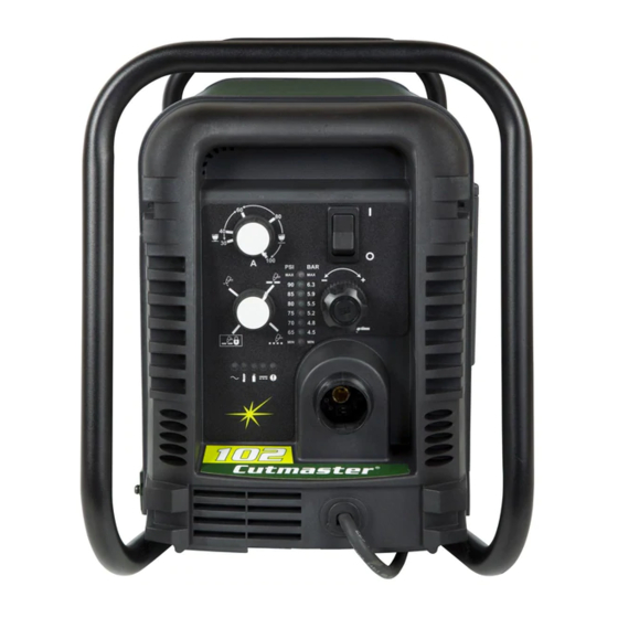
Page 20: Power Supply Features
102 2.06 Power Supply Features Handle and Leads Wrap Control Panel Torch Leads Receptacle Art # A-08359 Work Cable and Clamp Port for Optional Automation Interface Cable Input Power Selection Filter Assembly Gas Inlet Port Art # A-08360 Input Power Cord... -
Page 21: Section 2 Torch:introduction
102 SECTION 2 TORCH: 2T.03 Specifications INTRODUCTION A. Torch Configurations 1. Hand/Manual Torch, Models 2T.01 Scope of Manual The hand torch head is at 75° to the torch handle. The hand torches include a torch handle and torch This manual contains descriptions, operating trigger assembly. -
Page 22: 04 Options And Accessories
102 2T.05 Introduction to Plasma F. Torch Ratings Manual Torch Ratings A. Plasma Gas Flow Ambient 104° F Plasma is a gas which has been heated to an ex- Temperature 40° C tremely high temperature and ionized so that it... - Page 23 102 B. Gas Distribution E. Parts - In - Place (PIP) The single gas used is internally split into plasma The torch includes a 'Parts - In - Place' (PIP) circuit. and secondary gases. When the shield cup is properly installed, it closes a switch.
- Page 24 102 This Page Intentionally Blank INTRODUCTION 2T-4 Manual 0-4998...
-
Page 25: Section 3 System: Installation
102 SECTION 3 SYSTEM: INSTALLATION 3.01 Unpacking 1. Use the packing lists to identify and account for each item. 2. Inspect each item for possible shipping damage. If damage is evident, contact your distributor and / or shipping company before proceeding with the installation. -
Page 26: Primary Input Power Connections
102 3.03 Primary Input Power Connections CAUTION Check your power source for correct voltage before plugging in or connecting the unit. Check the Voltage Selector at the rear of the unit for correct setting before plugging in or connecting the unit. The primary power source, fuse, and any extension cords used must conform to local electrical code and the recommended circuit protection and wiring requirements as specified in Section 2. - Page 27 102 6. Connect the wires as follows. • Connect Bus Bar Jumpers on the contactor as shown in prior illustration and on label in the power supply. • Green / Yellow wire to Ground. 7. With a little slack in the wires, tighten the through - hole protector to secure the power cable.
-
Page 28: Gas Connections
102 3.04 Gas Connections Connecting Gas Supply to Unit The connection is the same for compressed air or high pressure cylinders. Refer to the following two subsections if an optional air line filter is to be installed. 1. Connect the air line to the inlet port. The illustration shows typical fittings as an example. - Page 29 102 Installing Optional Single - Stage Air Filter An optional filter kit is recommended for improved filtering with compressed air, to keep moisture and debris out of the torch. 1. Attach the Single - Stage Filter Hose to the Inlet Port.
- Page 30 102 Installing Optional Two - Stage Air Filter Kit This optional two - stage air line filter is also for use on compressed air shop systems. Filter removes moisture and contaminants to at least 5 microns. Connect the air supply as follows: 1.
-
Page 31: Section 3 Torch: Installation
3T.01 Torch Connections 2. Put the Function Control switch in the SET If necessary, connect the torch to the Power Sup- ply. Connect only the Thermal Dynamics model position. SL100 / Manual or SL100 / Mechanical Torch to 3. Place a welding filter lens in front of the this power supply. - Page 32 102 Pinch Block Assembly Square Workpiece A-02585 Mechanical Torch Set - Up 3. The proper torch parts (shield cup, tip, start cartridge, and electrode) must be installed for the type of operation. Refer to Section 4T.07, Torch Parts Selection for details.
-
Page 33: Section 4 System: Operation
102 SECTION 4 SYSTEM: OPERATION 4.01 Front Panel Controls / Features See Illustration for numbering Identification 1. Output Current Control Sets the desired output current. Output settings up to 60 Amps may be used for drag cutting (with the torch tip contacting the workpiece) or higher for standoff cutting. -
Page 34: Preparations For Operation
Set Operating Pressure Check that the torch is properly connected. Only 1. Place the Power Supply Function Control Thermal Dynamics model SL100 / Manual or SL100 / Mechanical Torches may be connected to this knob to the SET position. Gas will Power Supply. - Page 35 102 Typical Cutting Speeds STANDOFF CutMaster 102 Gas Pressure Settings Cutting speeds vary according to torch output am- perage, the type of material being cut, and opera- Leads SL100 SL100 tor skill. Refer to Section 4T.08 and following for...
- Page 36 102 This Page Intentionally Blank OPERATION Manual 0-4998...
-
Page 37: Section 4 Torch:operation
102 2. Remove the Electrode by pulling it straight SECTION 4 TORCH: out of the Torch Head. OPERATION Torch Head 4T.01 Torch Parts Selection Electrode Depending on the type of operation to be done determines the torch parts to be used. -
Page 38: 02 Cut Quality
102 4T.02 Cut Quality Bottom Dross Buildup Molten material which is not blown out of the cut NOTES area and resolidifies on the plate. Excessive dross Cut quality depends heavily on setup and may require secondary cleanup operations after parameters such as torch standoff, alignment with cutting. -
Page 39: 04 Hand Torch Operation
102 Torch Standoff Dross Improper standoff (the distance between the torch When dross is present on carbon steel, it is com- tip and workpiece) can adversely affect tip life as monly referred to as either “high speed, slow speed, well as shield cup life. - Page 40 102 2. Depending on the cutting operation, do one Trigger of the following: a. For edge starts, hold the torch perpen- dicular to the workpiece with the front of the tip on the edge of the workpiece at the point where the cut is to start.
- Page 41 102 piece during the cutting cycle. Shield Cup With Straight Edge 5. Hold the torch away from your body. The drag shield cup can be used with a non conduc- 6. Slide the trigger release toward the back tive straight edge to make straight cuts by hand.
- Page 42 102 6. Bring the torch within transfer distance to Piercing With Hand Torch the work. The main arc will transfer to the 1. The torch can be comfortably held in one work, and the pilot arc will shut off.
-
Page 43: 05 Gouging
102 4T.05 Gouging Pressure Setting Even though the setting is within the specified range, if the torch does not pilot well the pressure may need to be reduced. WARNINGS Lead Angle Be sure the operator is equipped with proper... -
Page 44: 06 Mechanized Torch Operation
102 4T.06 Mechanized Torch Operation For optimum smooth surface quality, the travel speed should be adjusted so that only the leading Cutting With Mechanized Torch edge of the arc column produces the cut. If the travel speed is too slow, a rough cut will be produced as... -
Page 45: 07 Parts Selection For Manual And Mechanized Torch Cutting
CutMaster 52 uses 60A and less Tip Gouging B 9-8226 (50 - 100 Amps) CutMaster 82 uses 80A and less CutMaster 102 uses 100A and less Art # A-08065_AB Tip Gouging C 9-8227 (60 - 120 Amps) CutMaster 152 uses 120A and less... - Page 46 102 4T.08 Recommended Cutting Speeds for Mechanized Torch With Exposed Type Torch: Mechanized With Exposed Tip Type Material: Mild Steel Type Plasma Gas: Air Type Secondary Gas: Single Gas Torch Thickness Output Amperage Speed (Per Minute) Standoff Plasma Gas Press...
- Page 47 102 Type Torch: Mechanized With Exposed Tip Type Material: Mild Steel Type Plasma Gas: Air Type Secondary Gas: Single Gas Torch Thickness Output Amperage Speed (Per Minute) Standoff Plasma Gas Press Flow (CFH) Pierce Pierce Height Inches mm (Cat. No.) Volts(VDC)
- Page 48 102 Type Torch: Mechanized With Exposed Tip Type Material: Aluminum Type Plasma Gas: Air Type Secondary Gas: Single Gas Torch Thickness Output Amperage Speed (Per Minute) Standoff Plasma Gas Press Flow (CFH) Pierce Pierce Height Inches mm (Cat. No.) Volts(VDC)
- Page 49 102 4T.09 Recommended Cutting Speeds for Mechanized Torch With Shielded Type Torch: Mechanized With Shielded Tip Type Material: Mild Steel Type Plasma Gas: Air Type Secondary Gas: Single Gas Torch Thickness Output Amperage Speed (Per Minute) Standoff Plasma Gas Press...
- Page 50 102 Type Torch: Mechanized With Shielded Tip Type Material: Mild Steel Type Plasma Gas: Air Type Secondary Gas: Single Gas Torch Thickness Output Amperage Speed (Per Minute) Standoff Plasma Gas Press Flow (CFH) Pierce Pierce Height Inches mm (Cat. No.)
- Page 51 102 Type Torch: Mechanized With Shielded Tip Type Material: Aluminum Type Plasma Gas: Air Type Secondary Gas: Single Gas Torch Thickness Output Amperage Speed (Per Minute) Standoff Plasma Gas Press Flow (CFH) Pierce Pierce Height Inches mm (Cat. No.) Volts(VDC)
-
Page 52: Patent Information
102 PATENT INFORMATION Plasma Cutting Torch Patents The following parts are covered under U.S. and Foreign Patents as follows: Catalog # Description Patent(s) 9-8215 Electrode US Pat No(s) 6163008; 6987238 Other Pat(s) Pending 9-8213 Cartridge US Pat No(s) 6903301; 6717096; 6936786;... - Page 53 102 Catalog # Description Patent(s) 9-8245 Shield Cap US Pat No(s) 6914211; D496951 Other Pat(s) Pending The following parts are also licensed under U.S. Patent No. 5,120,930 and 5,132,512: Catalog # Description 9-8235 Shield Cap 9-8236 Shield Cap 9-8237...
- Page 54 102 This Page Intentionally Blank OPERATION 4T-18 Manual 0-4998...
-
Page 55: Section 5 System:service
102 SECTION 5 SYSTEM: SERVICE 5.01 General Maintenance Maintain more often Warning! if used under severe Disconnect input power before maintaining. conditions Each Use Visual check of torch tip and electrode Weekly Visually inspect the cables and leads. Replace as needed... -
Page 56: Maintenance Schedule
4. Worn torch parts Daily Operational Checks or Every Six Cutting 5. Cutting current too low. Hours: 6. Non - Genuine Thermal Dynamics parts used Check torch consumable parts, replace if dam- 7. Incorrect gas pressure aged, worn or when cut performance has demi- Main Arc 1. -
Page 57: Fault Indicator
102 5.04 Fault Indicator Explanation of Faults UNDER PRESSURE: Indicates that operating pres- At initial power up, two lights will temporarily illu- sure is set too low and power supply output minate for 2-3 seconds to show the version of software power will be disabled. - Page 58 102 The second mode is a non-latched mode. The 85 PSI LED blinks at 5 cycles per second, indicating one of three fault modes exists: 1) While using an Automation Torch at current settings above 45 amps, the tip has contacted...
- Page 59 102 This Page Intentionally Blank Manual 0-4998 SERVICE...
-
Page 60: Basic Troubleshooting Guide
102 5.05 Basic Troubleshooting Guide WARNING There are extremely dangerous voltage and power levels present inside this unit. Do not attempt to diagnose or repair unless you have had training in power electronics measurement and troubleshooting techniques. Problem - Symptom Possible Cause... - Page 61 102 Problem - Symptom Possible Cause Recommended Action FAULT & 80 PSI 1. Torch shield cup is loose. 1. Tighten shield cup by hand. Do not overtighten. indicators flashing. 2. Torch tip, electrode or 2. Turn off power supply. Remove shield cup. Install missing Gas flow is cycling on start cartridge missing.
-
Page 62: Circuit Fault Isolation
102 5.06 Circuit Fault Isolation B. Cover Installation 1. Reverse previous procedures for cover installa- tion. WARNING NOTE The following procedures should not be attempted When installing the upper screws, attempt to by anyone who has not had proper training or reuse the original threads. - Page 63 If all of the Pre Power-Up Tests are ok, proceed with 3. Adjust the pressure regulator to set the gas pres- the trouble shooting guide. sure as specified in charts. STANDOFF CutMaster 102 Gas Pressure Settings CAUTION Leads SL100 SL100...
- Page 64 102 F. Pilot Arc Test • Current adjusts from 100 amps down to 20 amps There are three types of START signals which can be 3. Set the CURRENT CONTROL POTENTIOM- used to begin system operation: ETER to maximum position.
- Page 65 102 • Pilot Arc re-ignites immediately 2. Bring the torch to the work piece and transfer to cutting arc. 11. Open the torch switch • OK-TO-MOVE signal is present. (Meter shows • DC LED turns off continuity) After 20 second post flow time 3.
-
Page 66: Main Input And Internal Power Problems
102 C. Gas flows with ON/OFF SWITCH in OFF This completes the CNC Interface Test. If the above are all correct then the unit is functioning correctly. If the unit position does not function as stated, then note the symptom and 1. - Page 67 102 E. UNDER PRESSURE FAULT. AC LED on, 5. Defective Ribbon cable. FAULT INDICATOR and 60 PSI Indicator a) Check continuity of the ribbon cable connect- flashing. ing between the Main PCB 1 and the Logic PCB 3. 1. Air pressure source to unit is too low.
- Page 68 102 H. START ERROR FAULT. The FAULT 4. Open conductor in torch leads Indicator and 75 PSI LED flashing. a) Check continuity Start signal is active when SW1 is turned to ON 5. Defective Main PCB 1. position. b) Measure voltage at Main Pcb between J2-2 a) START can be active for one of the following: to test point GND1 for 12VDC.
- Page 69 102 K. AC LED on, TEMP, GAS, DC LED's are off, N. AC LED on, TEMP LED off, GAS LED on, FAULT Indicator is flashing. Gas flows. DC LED & FAULT indictor off. MIN PRESSURE LED is flashing. W1 contactor does not energize.
-
Page 70: Pilot Arc Problems
102 5.08 Pilot Arc Problems Defective Main PCB a) Replace Main PCB A. AC LED on, TEMP LED off, GAS LED on. Nothing happens when torch switch or If gas DOES flow out of SOL1 when the unit is in SET mode, reconnect SOL1 to the ATC connector. - Page 71 102 B. SHORTED TORCH (OUTPUT) FAULT. 4. Shorted Torch/leads Fault indicator and 85 PSI Indicators are a) Disconnect torch from unit. With consumables flashing at 1 cycle per second. removed from the torch, Check continuity of torch at ATC, between negative/plasma lead This is a Latched Failure Mode.
- Page 72 102 D. AC LED on, TEMP LED off, GAS LED on, G. Fans MOT1-3 do not not turn on after a gas flowing, DC LED, & Fault Indicator off, START signal is activated. No arc in torch. 1. Defective Logic PCB 3.
-
Page 73: Main Arc And Controls Problems
102 B. Main arc transfers but current cannot be a) Measure for 12VDC between J2-1 to J2-2 on PCB 2. If no voltage is present , replace Capaci- adjusted. tor PCB 2. 1. Defective Logic PCB 3. 2. Open connection between Capacitor PCB 2 J2 and a) While main arc is transferred,measure voltage 40A PCB 5 J3. -
Page 74: Cnc Interface Problems
102 5.11 Test Procedures F. INTERNAL ERROR FAULT INDICATOR AND 90 PSI INDICATOR FLASHING A. Main Contactor (W1) Test There has been a microprocessor problem. 1. Check continuity between: a) Turn ON/OFF SWITCH to OFF position and L1 to T1... - Page 75 102 B. PCB 1 Input Diode D1Test D. PCB 2 Capacitor / Relay Test 1. Using an ohmmeter perform the tests in the 1. Using an ohmmeter perform the tests in the chart: chart: Input Diode Module D1 on PCB1...
- Page 76 102 G. PCB 1 Output Diode D3 Test 3. Using an ohmmeter check continuity between the following points: 1. Disconnect transformer wires from Main PCB 1 PCB 1 Q2 terminal SEC1. Test points located on PCB 1* & PCB 2 2.
- Page 77 102 J. PCB 2 Capacitor / Relay Test (with PCB2 L. PCB 5 Input Diode Test. ( With PCB 2 removed from the unit) removed form unit) 1. Using an ohmmeter perform the following 1. Using an ohmmeter perform the following...
- Page 78 102 N. PCB 5 IGBT Test. ( With PCB 2 removed from unit) Using an ohmmeter perform the following checks:: PCB 5 - Q1 Test points located on PCB 5 Meter (+) Meter (-) Indication PRI 1 PMTH 1...
- Page 79 102 This Page Intentionally Blank Manual 0-4998 5-25 SERVICE...
- Page 80 102 PRI_4 J4 J3 I_DMD1 PRI_1 GND1 PRI_3 PRI_2 TIP1 SEC1 ELECTRODE1 +48V2 +12V2 -V_OUT1 +48V1 J8 J7 J6 J5 Art # A-08518 CHOKE1 SEC2 GND2 +12V1 WORK_1 MAIN PCB 1 LAYOUT MAIN PCB 1 SIGNALS J1-1 L1 Primary AC Line...
- Page 81 102 Signal Source/Destination J2-1 -VOUT (-) OUTPUT VOLTAGE J2-2 /TIP VOLTS Active high when tip is installed J2-3 TIP_SEN Approx. 100VDC while cutting w/ tip off work, Active low in Drag Mode J2-4 /460V_IN Active low with 460vac primary input voltage...
- Page 82 102 J4-1 3.3VDc J13-1 /OVERTEMP J4-2 J13-2 /FAN_ON J4-3 J13-3 /CSR J4-4 Common J13-4 CUR_SET J4-5 J13-5 MAIN_PCB_ID J13-6 Common J5-1 +12VDC MAIN PCB 1 LED INDICATORS J5-2 Not used J5-3 /SOLENOID D59 PCR Indicates Pilot IGBT gate signal is on...
- Page 83 102 PRI1 MTH8 MTH6 MTH1 MTH2 PMTH4 PMTH3 MTH7 PRI2 MTH4 80A_AC1 80A_AC3 80A_AC2 PMTH1 PMTH2 40A_AC1 Art # A-08505AB 40A_AC3 40A_AC2 CAPACITOR PCB 2 LAYOUT MTH7 CAP BANK B- CAPACITOR PCB 2 SIGNALS MTH8 CAP BANK B+ J1-1...
- Page 84 102 Art # A-08504 LOGIC PCB 3 LAYOUT SERVICE 5-30 Manual 0-4998...
- Page 85 102 LOGIC PCB 3 SIGNALS Signal info is the same as MAIN PCB 1 J2 connector. jJ3-1 +5VDC j3-2 Pressure Transducer output 0.5 to 5 VDC / 0 - 100 psi J3-3 Common LOGIC PCB 3 LED INDICATORS NORMAL INDICATION...
- Page 86 102 SEC1 CHOKE1 +OUT_1 SEC2 PMTH3 PMTH4 PRI3 PRI4 I_OUT1 GND1 I_DMD1 PRI2 PRI1 PMTH2 PMTH1 Art # A-08506 40AMP PCB 5 LAYOUT SERVICE 5-32 Manual 0-4998...
- Page 87 102 40AMP PCB 5 SIGNALS J1-1 +12VDC Supply for Fan MOT2 J1-2 /FAN Active Low to enable Fan MOT2 J2-1 +12VDC Supply for Fan MOT3 J2-2 /FAN Active Low to enable Fan MOT3 Signal Source/Destination J3-1 +12VDC +12VDC Supply...
- Page 88 102 This Page Intentionally Blank SERVICE 5-34 Manual 0-4998...
-
Page 89: Section 5 Torch:service
102 SECTION 5 TORCH: It is recommended to apply a very light film of o- ring lubricant (Catalog # 8-4025) to the o-rings on a SERVICE weekly basis. 5T.01 General Maintenance NOTE Upper Groove with Vent Holes Refer to Previous "Section 5 System" for common Must Remain Open and fault indicator descriptions. -
Page 90: 02 Inspection And Replacement Of Consumable Torch Parts
102 5T.02 Inspection and Replacement 4. Remove the tip. Check for excessive wear (indi- cated by an elongated or oversized orifice). Clean of Consumable Torch Parts or replace the tip if necessary. Good Tip Worn Tip WARNINGS Disconnect primary power to the system before disassembling the torch or torch leads. -
Page 91: Section 6:Parts Lists
The following items are included with the replacement power supply: work cable & clamp, input power cable, gas pressure regulator / filter, and operating manual. Description Catalog # CutMaster 102 Power Supply 208/230 - 460VAC, Single or 3 Phase, 60Hz, with 208/230 single phase input power cable and plug 3-1330-1... -
Page 92: Major External Replacement Parts
102 6.04 Major External Replacement Parts Item # Description Catalog # Cover with labels 9-0128 Base Enclosure Assembly 9-0186 Tube, roll handle 9-0121 Front Panel 9-0187 Rear Panel 9-0101 Art # A-08564 NOTE Illustration may vary slightly from unit. -
Page 93: Front Panel Replacement Parts
102 6.05 Front Panel Replacement Parts Item# Description Ref. Catalog # Output Current Control and Function Control Knobs 9-8527 Toggle - On/Off Switch 9-0109 Work Cable with Clamp, 20 Ft / 6.1 m 9-0189 Art # A-08123 NOTE Illustration may vary slightly from unit. -
Page 94: Left Side Replacement Parts
102 6.06 Left Side Replacement Parts Item # Description Catalog # Main PCB Assembly PCB1 9-0108 Main PCB Assembly 40 Amp PCB5 9-0194 Logic PCB PCB3 9-0107* Center Chassis Molded Plastic 9-0190 Fan, (3 total) MOT1-3 9-0104 Transformer, Main... -
Page 95: Right Side Replacement Parts
102 6.07 Right Side Replacement Parts Item # Description Catalog # Contactor, 4 Pole 9-8587 Solenoid, 12V SOL1 9-0114 Spare Parts Box 7-3267 Spare Parts Box Cover 7-3266 Console Quick Disconnect 9-0161 Regulator, with knob and mounting nut 9-0115*... -
Page 96: Replacement Power Supply Parts
102 6.08 Replacement Power Supply Parts Description Ref. Catalog # Regulator 9-0115 Filter Assembly Replacement Element 9-0116 Input Power Cord for 208 / 230 V Power Supply 9-0191 6.09 Options and Accessories Description Ref. Catalog # Single - Stage Filter Kit (includes Filter & Hose) -
Page 97: Replacement Parts For Hand Torch
102 6.10 Replacement Parts for Hand Torch Item # Description Catalog # Torch Handle Replacement Kit (includes items No. 2 & 3) 9-7030 Trigger Assembly Replacement Kit 9-7034 Handle Screw Kit (5 each, 6-32 x 1/2” cap screw, and wrench) 9-8062 Torch Head Assembly Replacement Kit (includes items No. -
Page 98: Replacement Parts - For Machine Torches With Unshielded Leads
102 6.11 Replacement Parts - for Machine Torches with Unshielded Leads Item No. Qty Description Catalog No. Torch Head Assembly without leads (includes items 2, 3, and 14) 9-8220 Large O - Ring 8-3487 Small O - Ring 8-3486... - Page 99 102 A-07994 Manual 0-4997 PARTS LIST...
-
Page 100: Torch Consumable Parts (Sl100 Sv)
102 6.12 Torch Consumable Parts (SL100 SV) Ohmic Clip 9-8224 20-40A Shield Tip: Shield Cap, Machine Cup Body, STANDOFF 40A 9-8245 9-8237 CUTTING 9-8205 Shield Cap, Deflector Shield Cup 9-8206 9-8243 9-8218 9-8208 Shield 50-60A Tips: Shield Cap, Machine... -
Page 101: Section 7: Replacement Procedures
102 SECTION 7: REPLACEMENT B. Procedure PROCEDURES 1. Open the wrist strap and unwrap the first two folds of the band. Wrap the adhesive side firmly around your wrist. 7.01 Scope 2. Unroll the rest of the band and peel the liner from the copper foil at the opposite end. -
Page 102: Major External Parts
102 7.04 Major External Parts C. Tube Handle Replacement Tools required: T20 Torx Driver A. Cover Removal 1. Remove the cover per subsection 7.04 A. Tools required: T20 Torx Driver 2. Remove the screws securing the tube handles to 1. -
Page 103: Front Panel Parts Replacement
102 7.05 Front Panel Parts Replacement D. Air Regulator Replacement Tools required: T20 Torx Driver, 11/16" Open End Refer to section 6.05 for Front Panel Replacement Parts Wrench and overall detailed drawing. 1. Remove the cover per subsection 7.04A A. -
Page 104: Left Side Internal Parts Replacement
102 G. Logic PCB (PCB3) Replacement Work Cable Replacement Tools required: T20 Torx Driver Flat Screw Driver, ½” Tools required: T20 Torx Driver wrench 1. Remove the Cover per subsection 7.04A. 1. Remove the cover per subsection 7.04A 2. Disconnect the work cable from the WORK1 2. - Page 105 102 B. Main Transformer (T1) Replacement 7. Loosen the two screws securing the W1 contactor to the base. Move the contactor out for clearance Tools required: T20 Torx Driver for the Center Chassis.. 1. Remove the Cover per subsection 7.04A 8.
-
Page 106: Rear Panel Parts Replacement
102 7.07 Rear Panel Parts Replacement 13. Install replacement Output Inductor by reversing the above steps. A. Filter Element Assembly Replacement 14. Reinstall the power supply cover. The Filter Element Assembly is in the rear panel. For Output Inductor (L2) better system performance, the filter element should be checked per the Maintenance Schedule (Subsection 5.02),... - Page 107 102 C. Input Power Cable Replacement 5. Remove the fitting from the filter element as- sembly by inserting a 6 mm hex wrench into Tools required: T20 Torx Driver, Phillips Head Screw- the internal hex fitting and turning it counter driver, Flathead Screwdriver, clock-wise (left).
- Page 108 102 5. Remove the Filter Element from the Housing and 6. Slide the replacement Filter Elements into the set Element aside to dry. Filter Assembly, with the same orientation as noted in Step 4 above. 6. Wipe inside of housing clean, then insert the replacement Filter Element open side first.
-
Page 109: Right Side Internal Parts Replacement
102 7.08 Right Side Internal Parts 6. Install the replacement Contactor by reversing the above steps. Replacement 7 Reinstall the power supply cover. A. Capacitor PCB (PCB2) Replacement D. 40 AMP PCB (PCB5) Replacement Tools required: T20 Torx Driver, #2 Phillips Head... - Page 110 102 This Page Intentionally Blank PARTS REPLACEMENT 7-10 Manual 0-4998...
-
Page 111: Appendix 1: Sequence Of Operation(Block Diagram
102 APPENDIX 1: SEQUENCE OF OPERATION (BLOCK DIAGRAM) ACTION: ACTION: ACTION: ACTION: RUN / Rapid Auto Restart / ON / OFF switch to ON Close external RUN / SET / LATCH disconnect switch. Rapid Auto Restart / switch to RUN... -
Page 112: Appendix 2: Data Tag Information
102 APPENDIX 2: DATA TAG INFORMATION West Lebanon, NH USA 03784 Manufacturer's Name and/or Logo, Location, Model and Revision Level, Serial Number Model: and Production Code Date of Mfr: Made in USA Type of Power Regulatory Standard Covering Supply (Note 1) -
Page 113: Appendix 3: Torch Pin - Out Diagrams
CUTMASTER 102 APPENDIX 3: TORCH PIN - OUT DIAGRAMS A. Hand Torch Pin - Out Diagram ATC Female Receptacle ATC Male Connector Front View Front View Negative / Negative / Plasma Plasma 8 - Open 8 - Ground 4 - Green /... -
Page 114: Appendix 4: Torch Connection Diagrams
CUTMASTER 102 APPENDIX 4: TORCH CONNECTION DIAGRAMS A. Hand Torch Connection Diagram Torch: SL60 / SL100 Hand Torch Leads: Torch Leads with ATC Connector Power Supply: with ATC Receptacle Male ATC Leads ATC Female Connector Receptacle Power Torch Torch Supply... - Page 115 102 This Page Intentionally Blank Manual 0-4997 APPENDIX...
-
Page 116: Appendix 5: System Schematic, 208/460V Units
CUTMASTER 102 APPENDIX 5: SYSTEM SCHEMATIC, 208/460V UNITS PRI 3 PRI 3 PRI 4 PRI 4 INRUSH RESISTORS +12VDC PRI 2 PRI 2 PRI 2 PRI 2 PRI 1 PRI 1 PRI 1 PRI 1 MTH1 MTH1 MTH2 MTH2 /INRUSH... - Page 117 Last Modified: Last Modified: Last Modified: Thursday, September 11, 2008 Thursday, September 11, 2008 Thursday, September 11, 2008 230/460 VAC CUTMASTER 102 & 152 230/460 VAC CUTMASTER 102 & 152 230/460 VAC CUTMASTER 102 & 152 42X1315 42X1315 42X1315 Manual 0-4997...
-
Page 118: Appendix 6: Publication History
102 APPENDIX 6: Publication History Cover Date Rev. Change(s) Sept. 25, 2008 Manual released. APPENDIX Manual 0-4997... - Page 119 GLOBAL CUSTOMER SERVICE CONTACT Thermadyne USA Thermadyne Asia Sdn Bhd Lot 151, Jalan Industri 3/5A 2800 Airport Road Denton, Tx 76207 USA Rawang Integrated Industrial Park - Jln Batu Arang 48000 Rawang Selangor Darul Ehsan Telephone: (940) 566-2000 800-426-1888 West Malaysia Telephone: 603+ 6092 2988 Fax: 800-535-0557 Fax : 603+ 6092 1085...
- Page 120 Corporate Headquarters 16052 Swingley Ridge Road Suite 300 St. Louis, MO 63017 Telephone: 636-728-3000 Email: TDCSales@Thermadyne.com www.thermadyne.com...
Need help?
Do you have a question about the CUTMASTER 102 and is the answer not in the manual?
Questions and answers