
Related Manuals for Thermal Dynamics CUTMASTER 39


Summary of Contents for Thermal Dynamics CUTMASTER 39
-
Page 1: Service Manual
CUTMASTER ™ PLASMA CUTTING SYSTEM Art # A-09431 Service Manual Rev. AC Date: February 24, 2010 Manual # 0-4976 Operating Features: 208-... - Page 3 Manufacturer assumes no liability for its use. Plasma Cutting Power Supply CutMaster™ 39 SL60 1Torch™ Service Manual Number 0-4976 Published by: Thermal Dynamics Corporation 82 Benning Street West Lebanon, New Hampshire, USA 03784 (603) 298-5711 www.thermal-dynamics.com Copyright 2007, 2008, 2009, 2010 by Thermadyne Corporation All rights reserved.
- Page 4 This Page Intentionally Blank...
-
Page 5: Table Of Contents
TABLE OF CONTENTS SECTION 1:GENERAL INFORMATION ...................1-1 1.01 Notes, Cautions and Warnings ..............1-1 1.02 Important Safety Precautions ..............1-1 1.03 Publications....................1-2 1.04 Note, Attention et Avertissement ..............1-3 1.05 Precautions De Securite Importantes ............1-3 1.06 Documents De Reference ................1-5 1.07 Declaration of Conformity ................1-6 1.08 Statement of Warranty ................1-7 SECTION 2 SYSTEM:INTRODUCTION .................2-1... - Page 6 TABLE OF CONTENTS SECTION 5 SYSTEM: SERVICE .....................5-1 5.01 General Maintenance .................5-1 5.02 Common Faults ...................5-6 5.03 Circuit Fault Isolation ..................5-6 5.04 Main Input and Internal Power Problems ............5-7 5.05 Pilot Arc Problems ..................5-9 5.06 Main Arc Problems..................5-10 5.07 Test Procedures ..................5-10 5.08 Anti-Static Handling Procedures ...............5-12 5.09...
-
Page 7: Section 1:General Information
39 SECTION 1: • The kinds of fumes and gases from the plasma arc depend on the kind of metal being used, coatings on the metal, and the GENERAL INFORMATION different processes. You must be very careful when cutting... -
Page 8: Publications
39 • Do not cut or weld on containers that may have held combus- 1.03 Publications tibles. Refer to the following standards or their latest revisions for more • Provide a fire watch when working in an area where fire hazards information: may exist. -
Page 9: Note, Attention Et Avertissement
39 1.04 Note, Attention et Avertissement • Les sortes de gaz et de fumée provenant de l’arc de plasma dépen- dent du genre de métal utilisé, des revêtements se trouvant sur le Dans ce manuel, les mots “note,” “attention,” et “avertissement” sont métal et des différents procédés. - Page 10 39 produit du métal, des étincelles, des scories chaudes pouvant mettre le feu aux matières combustibles ou provoquer l’explosion de fumées inflammables. BRUIT • Soyez certain qu’aucune matière combustible ou inflammable ne Le bruit peut provoquer une perte permanente de l’ouïe. Les procédés se trouve sur le lieu de travail.
-
Page 11: Documents De Reference
39 1.06 Documents De Reference 14. Norme AWSF4.1 de l’Association Américaine de Soudage, RECOM- MANDATIONS DE PRATIQUES SURES POUR LA PRÉPARATION À Consultez les normes suivantes ou les révisions les plus récentes ayant LA COUPE ET AU SOUDAGE DE CONTENEURS ET TUYAUX AYANT été... -
Page 12: Declaration Of Conformity
Rigorous testing is incorporated into the manufacturing process to ensure the manufactured product meets or exceeds all design specifications. Thermal Dynamics has been manufacturing products for more than 30 years, and will continue to achieve excellence in our area of manufacture. Manufacturers responsible representative:... -
Page 13: Statement Of Warranty
This warranty is exclusive and in lieu of any warranty of merchantability or fitness for a particular purpose. Thermal Dynamics will repair or replace, at its discretion, any warranted parts or components that fail due to defects in material or workmanship within the time periods set out below. - Page 14 39 GENERAL INFORMATION Manual 0-4976...
-
Page 15: Section 2 System:introduction
Electronic copies of this manual can also be downloaded at no charge in Acrobat PDF format by going to the Thermal Dynamics web site listed below and clicking on Thermal Dynamics and then on the Literature link: http://www.thermal-dynamics.com Manual 0-4976... -
Page 16: Power Supply Specifications
120V/15A with NEMA 5-15P plug or 240V/20A with NEMA 6-50P plug Output Current 20-30 Amps, continuously variable Power Supply Gas Filtering Ability Particulates to 20 Microns CutMaster 39 Power Supply Duty Cycle (Note 2) Ambient Temperature 104° F (40° C) Duty Cycle... -
Page 17: Input Wiring Specifications
Provide clearance for proper air flow through the power supply. Operation without proper air flow will inhibit proper cooling and reduce duty cycle. 2.05 Input Wiring Specifications CutMaster 39 Input Power Requirements Input Power Input Current Input Suggested Sizes (See Notes) -
Page 18: Power Supply Options And Accessories
Combination of ambient air and gas stream through torch E. SL60 Torch Ratings (Refer to Note) NOTE Ratings shown apply to the SL60 Torch only. Refer to the Specifications chart on page 2T-1 for CutMaster 39 data. F. Plasma Power Supply Used With •... -
Page 19: Section 2 Torch:introduction
39 SECTION 2 TORCH: 2T.03 Specifications INTRODUCTION A. Torch Configurations 1. Hand Torch, Model SL60 2T.01 Scope of Manual The hand torch head is at 75° to the torch handle. The hand torches include a torch handle and torch This manual contains descriptions, operating trigger assembly. -
Page 20: 04 Options And Accessories
39 2T.05 Introduction to Plasma H. Gas Requirements SL60 Torch Gas Specifications A. Plasma Gas Flow Gas (Plasma and Secondary) Compressed Air Plasma is a gas which has been heated to an ex- Operating Pressure 60 - 75 psi... - Page 21 39 B. Gas Distribution The single gas used is internally split into plasma and secondary gases. The plasma gas flows into the torch through the negative lead, through the starter cartridge, around the electrode, and out through the tip orifice.
- Page 22 39 This Page Intentionally Blank INTRODUCTION 2T-4 Manual 0-4976...
-
Page 23: Section 3: Installation
39 SECTION 3: INSTALLATION 3.01 Unpacking 1. Use the packing lists to identify and account for each item. 2. Inspect each item for possible shipping damage. If damage is evident, contact your distributor and / or ship- ping company before proceeding with the installation. -
Page 24: Primary Input Power Connections
39 3.03 Primary Input Power Connections CAUTION Check your power source for correct voltage before plugging in or connecting the unit. The primary power source, fuse, and any extension cords used must conform to local electrical code and the recommended circuit protection and wiring requirements as specified in Section 2. -
Page 25: Gas Connections
39 3.04 Gas Connections A. Connecting Gas Supply to Unit The connection is the same for compressed air or high pressure gas cylinders. Refer to subsection 3.4-C if an optional air line filter is to be installed. 1. Connect the gas line to the inlet port. The illustration shows typical fittings as an example. - Page 26 39 C. Installing Optional Single - Stage Air Filter An optional filter kit is recommended for improved filtering with compressed air, to keep moisture and debris out of the torch. 1. Attach the Single - Stage Filter Hose to the Inlet Port.
-
Page 27: Torch Connections
39 3.05 Torch Connections If necessary, connect the torch to the Power Supply. Connect only the Thermal Dynamics model SL60 Torch to this power supply. WARNING Disconnect primary power at the source before connecting the torch. 1. Align the male connector (on the torch lead) with the female receptacle on the power supply. - Page 28 39 This Page Intentionally Blank INSTALLATION Manual 0-4976...
-
Page 29: Section 4 System:operation
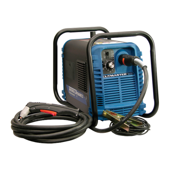
39 SECTION 4 SYSTEM: OPERATION 4.01 Product Features A. General Features Handle and Leads Wrap Gas Pressure Knob Torch Leads Connector Art # A-07930 Control Panel Work Cable and Clamp Manual 0-4976 OPERATION... - Page 30 39 B. Control Panel A-07931 1. ON / OFF Switch Controls input power to the power supply. Up is ON, down is OFF. 2. RUN / SET Switch RUN (up) position is for general torch operation. SET (down) position is for setting gas pressure and purging lines.
-
Page 31: Preparations For Operating
Check the torch for proper assembly and appropriate torch parts. The torch parts must correspond with the type of operation, and with the amperage output of this Power Supply (30 amps maximum). Use only genuine Thermal Dynamics parts with this torch. Art # A-03409 Large O-Ring, Cat. - Page 32 39 D. Gas Selection Ensure gas source meets requirements (refer to Section 2). Check connections and turn gas supply on. E. Connect Work Cable Clamp the work cable to the workpiece or cutting table. The area must be free from oil, paint and rust. Connect only to the main part of the workpiece;...
- Page 33 39 G. Set Operating Pressure Place the Power Supply RUN / SET switch to the SET (down) position. Gas will flow. Adjust gas pressure to 65 psi / 4.5 bar. Gas indicator turns on. NOTE If gas regulator leaks, reset gas pressure to 0 psi, then reset to 65 psi / 4.5 bar.
- Page 34 39 Cutting Operation Refer to Section 1, Important Safety Precautions. Wear heavy welding gloves and protective clothing. Protect eyes with appropriate shielding. Aim the torch head away from yourself. Slide the trigger release to the rear. Squeeze and hold the trigger. Gas flows for approximately 1 second, then shuts off briefly. The pilot arc then starts.
-
Page 35: Sequence Of Operation
39 4.03 Sequence of Operation The following is a typical sequence of operation for this power supply. Refer to Appendix 1 for block diagram. 1. Plug the input power cord into an active circuit. a. AC power is available at the Power Supply. - Page 36 39 This Page Intentionally Blank OPERATION Manual 0-4976...
-
Page 37: Section 4 Torch:operation
39 SECTION 4 TORCH: NOTE Refer to Appendix Pages for additional informa- OPERATION tion as related to the Power Supply used. Power On 4T.01 Introduction Place the ON - OFF Switch on the Power Supply to This section provides a description of the SL60 the ON position. -
Page 38: 05 Cut Quality
39 4T.05 Cut Quality NOTE Refer to Section 6 and the Appendix Pages for NOTES additional information on torch parts. Cut quality depends heavily on setup and pa- Change the torch parts for a different operation as rameters such as torch standoff, alignment with... -
Page 39: 06 General Cutting Information
39 Top - Edge Rounding Torch Standoff Rounding on the top edge of a cut due to wearing Improper standoff (the distance between the torch from the initial contact of the plasma arc on the tip and workpiece) can adversely affect tip life as workpiece. -
Page 40: 07 Hand Torch Operation
39 b. For standoff cutting, hold the torch 1/8 Dross - 3/8 in (3-9 mm) from the workpiece as When dross is present on carbon steel, it is com- shown below. monly referred to as either “high speed, slow speed, or top dross”. - Page 41 39 NOTE Drag Cutting With a Hand Torch The gas preflow and postflow are a characteristic Drag cutting works best on metal 3/16" (4.7 mm) of the power supply and not a function of the thick or less. torch.
- Page 42 39 7. Bring the torch within transfer distance to NOTE the work. The main arc will transfer to the The tip should never come in contact with the work, and the pilot arc will shut off. workpiece except during drag cutting opera- tions.
-
Page 43: 08 Recommended Cutting Speeds
39 4T.08 Recommended Cutting Speeds Cutting speeds vary according to torch output, the type of material being cut, and operator skill. Speeds shown are typical for this cutting system using air plasma to cut mild steel, with output current at 30 amps and torch held at 0 - 1/16"... - Page 44 39 Optimum torch travel speed is dependent on current setting, lead angle, and mode of operation (hand or machine torch). Current Setting Current settings depend on torch travel speed, mode of operation (hand or machine torch), and the amount of material to be removed.
-
Page 45: Section 5 System: Service
39 SECTION 5 SYSTEM: SERVICE 5.01 General Maintenance Maintain more often Warning! if used under severe Disconnect input power before maintaining. conditions Each Use Visual check of torch tip and electrode Weekly Visually inspect the cables and leads. Replace as needed... - Page 46 39 A. Each Use Check torch consumables for wear, replace if necessary. WARNING Shut off power before inspecting or removing torch parts. NOTE When operating the torch in a normal condition, a small amount of gas vents through the gap between the shield cup and torch handle.
- Page 47 39 B. Every three months A. Check internal air filter, replace if necessary. 1. Shut off input power; turn off the gas supply. Bleed down the gas supply. 2. Remove the upper cover screws. 3. Loosen the lower screws. Pull the cover up and away from the unit.
- Page 48 39 4. Pull the upper end of the drain tube off the fitting on the filter bowl 5. Unscrew the bowl. The filter element will be visible and still attached to the main body of the Regulator / Filter.
- Page 49 39 C. O-Ring Lubrication D. Check Optional Single - Stage Filter Element, replace if necessary. An o-ring on the Torch ATC Male Connector requires lubrication on a regular basis, depending on how 1. Shut off input power. frequently the torch is disconnected and re-con- 2.
-
Page 50: Common Faults
After re- 5. Cutting current too low. pairs are complete, run the following tests again 6. Non - Genuine Thermal Dynamics to verify that the unit is fully operational. parts used 7. Incorrect gas pressure A. -
Page 51: Main Input And Internal Power Problems
39 C. Pilot Arc Test C. Fan does not operate; AC indicator is OFF 1. Close the torch switch and check the fol- 1. Front Panel ON/OFF switch in OFF lowing: (down) position • Gas flows briefly, then stops. - Page 52 39 2. Dirty or defective starter cartridge D. AC indicator flashing, TEMP indicator OFF a. Check starter cartridge; clean or replace (on system start-up); RUN / SET switch in RUN position as needed. 3. Wire E8 not connected to PC Board termi- 1.
-
Page 53: Pilot Arc Problems
39 4. Faulty PC board 5.05 Pilot Arc Problems a. Leave RUN/SET switch in SET posi- Locate your symptom below: tion. Disconnect wire harness from A. No pilot arc; Gas flows continuously; AC terminal J1 on PC board. Test voltage indicator ON;... -
Page 54: Main Arc Problems
39 5.07 Test Procedures D. No gas flow; AC and GAS indicators ON, TEMP and DC indicators OFF The test procedures in this subsection are refer- 1. Upper O-ring on torch head is in wrong po- enced in the troubleshooting section. - Page 55 39 B. Opening Power Supply Enclosure C. Diode Testing Basics The cover of the Power Supply must be removed Testing of diode modules requires a digital volt/ to gain access to the input power connections. ohmmeter that has a diode test scale. Remember that even if the diode module checks good, it may still be bad.
-
Page 56: Anti-Static Handling Procedures
39 6. Reverse the meter leads across the diode Disconnect primary input power. With an ohm- for reverse bias testing (refer to following meter set on the diode range, make the following figure). A properly functioning diode will checks on both diode bridges:... -
Page 57: Parts Replacement - General Information
39 Before disassembling any part of the Power B. Procedure Supply first read the procedure for the part to be 1. Open the wrist strap and unwrap the first replaced, then proceed with the disassembly two folds of the band. Wrap the adhesive side firmly around your wrist. - Page 58 39 9. Connect the input power cable to the power. Test the Power Supply for proper replacement switch, with the wires posi- operation. tioned as noted previously. 5.06 Left Side Internal Parts Replace- 10. Transfer wires E1 and E2 to the replace- ment ment switch.
-
Page 59: Rear Panel Parts Replacement
39 A. Pressure Gauge Replacement Thermal Pad 1. Disconnect the gas input line from the Power Supply. 2. Remove the cover per Subsection 5.07-B. E16A 3. Disconnect the gas tube from the Pressure Diode Bridge 1 Switch Assembly Adapter Fitting. Hold... -
Page 60: Right Side Internal Parts Replacement
39 14. Reinstall the Power Supply cover. Con- 5.13 Right Side Internal Parts nect the gas input line to the inlet port. Replacement Connect the Power Supply to primary input Refer to Section 6 for Right Side Internal power. - Page 61 39 B. Pressure Switch Replacement 1. Remove the cover per Subsection 5.04-A. 2. Label and disconnect the wires to the Pres- sure Switch. 3. Turn the Pressure Switch to remove it from the Regulator/Filter Assembly. 4. Apply thread sealant to the threads of the replacement Pressure Switch.
- Page 62 39 This Page Intentionally Blank SERVICE 5-18 Manual 0-4976...
-
Page 63: Section 5 Torch:service
39 SECTION 5 TORCH: O-Ring Lubrication SERVICE An o-ring on the Torch ATC Male Connector requires lubrication on a scheduled basis. This will allow the o-ring to remain pliable and provide a proper seal. The o-ring will dry out, becoming hard and cracked, 5T.01 General Maintenance... -
Page 64: 02 Inspection And Replacement Of Consumable Torch Parts
39 5T.02 Inspection and Replacement 3. Remove the tip. Check for excessive wear (indi- cated by an elongated or oversized orifice). Clean of Consumable Torch Parts or replace the tip if necessary. Good Tip Worn Tip WARNINGS Disconnect primary power to the system before disassembling the torch or torch leads. -
Page 65: Section 6:Parts Lists
The following items are included with the replacement power supply: input power cord and plug, work cable & clamp, gas pressure regulator / filter, and operating manual. Description Catalog # CutMaster 39 Power Supply 3-3830 Surelok Model SL60 Torch 7-5204 6.04 Power Supply Replacement Parts... -
Page 66: Major External Replacement Parts
39 6.05 Major External Replacement Parts Item # Description Catalog # Cover with labels 9-0173 Base Enclosure Assembly 9-0174 Tube, roll handle 9-0121 Front Panel 9-0175 Rear Panel 9-0176 Art # A-08110 NOTE Illustration may vary slightly from unit. -
Page 67: Front Panel Replacement Parts
39 6.06 Front Panel Replacement Parts Item# Description Ref. Catalog # On/Off Switch 8-4248 Output Current Control Potentiometer with wire harness 9-8527 Run/Set Switch 9-1042 Output Current Control Knob 9-8527 Work Cable with Clamp, 20 Ft / 6.1 m... -
Page 68: Left Side Replacement Parts
39 6.07 Left Side Replacement Parts Item # Description Catalog # PCB Assembly 9-0178 Diode Bridge BR1, BR2 7-3345 Thermal Pad 9-4466 Input Power Cable with plug, for non-CE units 9-8660 Input Power Cable for CE units 9-8671 Input Power Cable for (CE) Australian units... -
Page 69: Right Side Replacement Parts
39 6.08 Right Side Replacement Parts Item # Description Catalog # Console ATC Assembly 9-8641 Regulator/Filter Assembly (includes Pressure Switch, 9-0180 Pressure Gauge, Solenoid) Pressure Gauge 9-0181 Pressure Switch 9-1044 Regulator/Filter Replacement Element 9-0182 Regulator Mounting Nut 9-0183 Assembly, Output Inductor... -
Page 70: Options And Accessories
39 6.09 Options and Accessories Description Catalog # 120V, 15 - Amp Plug 9-8644 120V, 20 - Amp Receptacle 9-8645 Single - Stage Filter Kit (includes Filter & Hose) 7-7507 Replacement Filter Body 9-7740 Replacement Filter Hose (not shown) -
Page 71: Torch Consumables
39 6.10 Torch Consumables Art # A-03409 Large O-Ring, Cat. No. 8-3487 Small O-Ring, Cat. No. 8-3486 Electrode, Cat. No. 9-8215 Start Cartridge, Cat. No. 9-8213 30Amp Cutting Tip, Cat. No. 9-8206 Shield Cup, Cat. No. 9-8218 Worn Electrode... -
Page 72: Patent Information
39 PATENT INFORMATION The following parts are licensed under U.S. Patent No(s). 5120930 and 5132512 Catalog Number Description 9-8235 Shield Cap, Drag 50-60A 9-8236 Sheild Cap, Drag 70-100A 9-8237 Shield Cup, Body 9-8238 Shield Cap, Machine 50-60A 9-8239 Shield Cap, Machine 70-100A... -
Page 73: Appendix 1: Sequence Of Operation(Block Diagram
39 APPENDIX 1: SEQUENCE OF OPERATION (BLOCK DIAGRAM) ACTION ACTION ACTION ACTION ACTION ON / OFF switch Connect work cable Close external RUN / SET switch to SET. RUN / SET switch to ON. to RUN. to workpiece. disconnect switch. -
Page 74: Appendix 2: Data Tag Information
39 APPENDIX 2: DATA TAG INFORMATION West Lebanon, NH USA 03784 Manufacturer's Name and/or Logo, Location, Model and Revision Level, Serial Number Model: and Production Code Date of Mfr: Made in USA Type of Power Regulatory Standard Covering Supply (Note 1) -
Page 75: Appendix 3: Main Power Pc Board Layout
39 APPENDIX 3: MAIN POWER PC BOARD LAYOUT TP16 MAIN PCB ASSEMBLY 19X1773 REV OVER-TEMP PRESSURE RUN/SET TEST TEMP E14B E14A TP20 TORCH SWITCH E15B E15A TP101 E12A TP23 TP23 TP24 E12A E12B TP26 E12B TP26 E16B E16A E16B... -
Page 76: Appendix 4: Main Pc Board Wiring
39 APPENDIX 4: MAIN PC BOARD WIRING To Temperature To Pressure Sensor To Fan Switch To Solenoid MAIN PCB ASSEMBLY 19X1773 REV OVER-TEMP PRESSURE RUN/SET TEST To Current Control To Torch TEMP Receptacle To Run / Set Switch TP20... -
Page 77: Appendix 5: Torch Connector Diagram
39 APPENDIX 5: TORCH CONNECTOR DIAGRAM ATC Female Receptacle ATC Male Connector Front View Front View Negative / Negative / Plasma Plasma 8 - Open 8 - Open 4 - Green / Switch 4 - Switch 3 - Switch... -
Page 78: Appendix 6: System Schematic
39 APPENDIX 6: SYSTEM SCHEMATIC PFC INDUCTOR INPUT 230V ONLY TEST E M C FILTER E12A CE ONLY CHASSIS GND (E12A) (E15A) (E1) (E14A) E14A 120/208/230V INPUT (E16A) 50/60HZ (E2) E15A STUD E16A E12B BIAS (E12B) FAN1 CONVERTER 12VDC... - Page 79 603-298-5711 REL ECO 100535 2/27/03 Date: REL ECO B505 6/19/07 Information Proprietary to THERMAL DYNAMICS CORPORATION. Tuesday, May 15, 2001 Not For Release, Reproduction, or Distribution without Written Consent. Drawn:References NOTE: Unless Otherwise Specified, Resistors are in Ohms 1/4W 5%.
- Page 80 39 This Page Intentionally Blank. APPENDIX Manual 0-4976...
- Page 81 GLOBAL CUSTOMER SERVICE CONTACT Thermadyne USA Thermadyne Asia Sdn Bhd Lot 151, Jalan Industri 3/5A 2800 Airport Road Denton, Tx 76207 USA Rawang Integrated Industrial Park - Jln Batu Arang 48000 Rawang Selangor Darul Ehsan Telephone: (940) 566-2000 800-426-1888 West Malaysia Telephone: 603+ 6092 2988 Fax: 800-535-0557 Fax : 603+ 6092 1085...
Need help?
Do you have a question about the CUTMASTER 39 and is the answer not in the manual?
Questions and answers