Sign In
Upload
Manuals
Brands
Reer Manuals
Controller
MOSAIC MR2
Reer MOSAIC MR2 Manuals
Manuals and User Guides for Reer MOSAIC MR2. We have
6
Reer MOSAIC MR2 manuals available for free PDF download: Installation And Use Manual, Quick Installation Manual
Reer MOSAIC MR2 Installation And Use Manual (266 pages)
MODULAR SAFETY INTEGRATED CONTROLLER
Brand:
Reer
| Category:
Controller
| Size: 19.27 MB
Table of Contents
Table of Contents
2
Introduction
9
Contents of this Handbook
9
Important Safety Instructions
9
Abbreviations and Symbols
10
Applicable Standards
11
Overview
12
Master MOSAIC M1 / MOSAIC M1S / MOSAIC M1S COM
12
MOSAIC M1S COM Key Features
13
MOSAIC M1S COM and Mbx in the same Project: Fieldbus Management
14
Expansion Modules
14
MSD Software
15
Product Composition
16
Installation
17
MOSAIC M1, MOSAIC M1S, Expansion Modules Mechanical Fastening
17
MOSAIC M1S COM Mechanical Fastening
18
Calculation of Safety Distance of an ESPE Connected to MOSAIC
19
Electrical Connections
19
Instructions Concerning Connection Cables
20
Master Module MOSAIC M1
20
Master Modules MOSAIC M1S / MOSAIC M1S COM
21
USB Interface
22
LAN Interface (RJ45)
22
MOSAIC Configuration Memory (MCM)
22
MULTIPLE LOAD Function
22
RESTORE Function
23
Compatibility between MCM Memory and Master Modules
23
New MCM Features with F.w. 2.0.0
23
Module MI8O2
24
Module MI8O4
25
Module MI8
26
Module MI12T8
26
Module MI16
27
Module MO2
27
Module MO4
28
Module MO4L
28
Module MR2
29
Module MR4
29
Module MR8
30
Modules MV0 - MV1 - MV2
31
Encoder Connections with RJ45 Connector (MV1, MV2)
31
Module MOR4
33
Module MOR4S8
33
Module MOS8
34
Module MOS16
34
Module MO4LHCS8
35
Modulo MA2
35
Modulo MA4
36
MA2 / MA4 Analog Sensor Connections
37
Example of Connection of Mosaic to the Machine Control System
38
Checklist after Installation
38
Operating Diagram
39
Signals
40
Inputs
40
Master Enable
40
Node Sel
40
Proximity Input for Speed Controller MV
40
Configuration with Interleaved Proximity
41
Restart_Fbk
41
Outputs
42
OUT STATUS (SIL 1/PL C)
42
Out Test
42
Ossd Safety Outputs
43
Important Note Concerning OSSD Safety Outputs
43
Ossd (Mosaic M1, Mi8O2, Mo2, Mo4)
43
Ossd (Mosaic M1S, Mosaic M1S Com, Mi8O4, Mo4L)
43
Ossd (Mo4Lhcs8)
45
Ossd Outputs Configuration
46
Safety Relays (Mr2, Mr4, Mr8, Mor4, Mor4S8)
47
Characteristics of the Output Circuit
47
MR2/MR4/MR8 Internal Contacts Diagram
47
Example of MR2 Module Connection with Static OSSD of a Module MOSAIC M1
48
Switching Operation Timing Diagram
49
Technical Features
50
General System Characteristics
50
Safety Level Parameters
50
General Data
50
Enclosure
51
MOSAIC M1 Module
52
MOSAIC M1S Module
52
MOSAIC M1S COM Module
53
MI8O2 Module
53
MI8O4 Module
54
MI8 - MI16 Modules
54
MI12T8 Module
54
MO2 - MO4 Modules
55
MO4L Module
55
MOS8 - MOS16 Modules
55
MR2 - MR4 - MR8 Modules
56
MOR4 - MOR4S8 Module
56
MO4LHCS8 Module
57
MV0 - MV1 - MV2 Modules
57
MA2, MA4 Module
58
Mechanical Dimensions
59
LED INDICATORS (Normal Operation)
60
Master MOSAIC M1 (Figure 20)
60
Master MOSAIC M1S (Figure 20)
61
Master MOSAIC M1S COM (Figure 20)
62
MOSAIC M1S COM Specific Fieldbus LED Indicators
63
Ethercat Leds
63
LED State Explanation
63
Ethernet/Ip Leds
64
LED State Explanation
65
Modbus/Tcp Leds
65
PROFINET Leds
66
LED State Explanation
66
MI8O2 (Figure 23)
67
MI8O4 (Figure 23)
68
MI8 (Figure 25)
69
MI12T8 (Figure 27)
70
MI16 (Figure 27)
71
MO2 (Figure 28)
72
MO4 (Figure 29)
73
MO4L (Figure 23)
74
MOR4 (Figure 31)
75
MOR4S8 (Figure 32)
76
MOS8 (Figure 33)
77
MOS16 (Figure 34)
78
MV0, MV1, MV2 (Figure 35)
79
MR2, MR4, MR8 (Figure 36)
80
MO4LHCS8 (Figure 37)
81
MA2, MA4 (Figure 38)
82
LED INDICATORS (Troubleshooting)
83
Master MOSAIC M1 (Figure 39)
83
Master MOSAIC M1S / MOSAIC M1S COM (Figure 40)
84
MI8O2 (Figure 41)
85
MI8O4 (Figure 42)
86
MI8 (Figure 43)
87
MI12T8 (Figure 44)
88
MI16 (Figure 45)
89
MO2 / MO4 (Figure 46)
90
MO4L (Figure 47)
91
MOR4 (Figure 48)
92
MOR4S8 (Figure 49)
93
MOS8 (Figure 50)
94
MOS16 (Figure 51)
95
MV0, MV1, MV2 (Figure 52)
96
MO4LHCS8 (Figure 53)
97
MA2, MA4 (Figure 54)
98
Mosaic Safety Designer Software
100
Installing the Software
100
PC HARDWARE Requirements
100
PC SOFTWARE Requirements
100
Installation of MSD Software
100
Fundamentals
101
Standard Toolbar
102
Textual Toolbar
103
Create a New Project (Configure the MOSAIC System)
103
Pages Configuration / Management
104
Fieldbus with Dynamic Input Order
106
Create a New Project: MOSAIC M1S COM Fieldbus Parameters Configuration
106
Modbus TCP Parameters
106
Ethernet/Ip Parameters
107
Profinet RT Parameters
107
Ethercat Parameters
108
Edit Configuration (Composition of the Various Modules)
109
Change User Parameters
109
Objects - Operator - Configuration Toolbars
110
Creating the Diagram
111
Use of Mouse Right Button
112
Example of a Project
113
Project Validation
113
Resources Allocation
114
Project Report
115
Connect MSD to Mosaic Master
117
Communication Channel Selection
117
USB Connection
117
Network Connection (MOSAIC M1S COM Only)
117
Connected Master Parameters Visualization
121
MOSAIC M1S COM Connected Via LAN
121
MOSAIC M1S COM Connected Via USB
121
MOSAIC M1/MOSAIC M1S Connected Via USB
122
Operations Available with Master Connected (MOSAIC M1S COM)
123
Visualization Network Parameters
123
Visualization/Setting Network Parameters (MOSAIC M1S COM)
123
Download Project to MOSAIC (from PC)
124
Upload an Existing Project to PC (from MOSAIC)
125
Configurations LOG
125
System Composition
125
Errors Log
126
Disconnecting System
126
Monitor Functions
126
Monitor (I/O Status in Real Time - Textual)
126
Monitor (I/O Status in Real Time - Textual - Graphic)
127
Monitor (I/O with Diagnostic)
127
Fieldbus Monitor (Only for MOSAIC M1S COM)
128
Password Protection
129
Level 1 Password
129
Level 2 Password
130
Maintenance Password (MOSAIC M1S, MOSAIC M1S COM)
130
Password Change
130
Testing the System
131
Object Function Blocks
132
Output Objects
132
OSSD (Safety Outputs)
132
SINGLE-DOUBLE OSSD (Safety Output)
133
STATUS (SIL 1/PL C Output)
136
Fieldbus Probe
137
Relay
138
Use with RESTART: Automatic (A) or Manual (B) (Category 2)
139
Input Objects
141
E-STOP (Emergency Stop)
141
E-GATE (Safety Gate Device)
142
SINGLE E-GATE (Safety Gate Device)
143
Lock Feedback
144
ENABLE (Enable Key)
145
ESPE (Optoelectronic Safety Light Curtain / Laser Scanner)
146
FOOTSWITCH (Safety Pedal)
147
MOD-SEL (Safety Selector)
149
PHOTOCELL (Safety Photocell)
149
TWO-HAND (Bimanual Control)
150
Network_In
151
Sensor
151
S-MAT (Safety Mat)
152
Switch
153
Enabling Grip Switch
154
Testable Safety Device
155
RFID (RFID Safety Sensor)
157
Solid State Device
158
Restart Input
159
Fieldbus Input
159
Ll0-Ll1
160
Comments
160
Title
160
Speed Control Type Function Blocks
161
Warning Concerning Safety
161
Note Concerning Speed Control Function Blocks
161
Speed Control
162
Window Speed Control
165
Stand Still
167
Stand Still and Speed Control
169
Speed Equality Check
172
Analog Input Type Function Blocks
173
ANALOG INPUT (4 Inputs each MA4 Module, 2 Inputs each MA2 Module)
173
ANALOG DIVISION (4 Inputs each MA4 Module, 2 Inputs each MA2 Module)
184
Operator Function Blocks
197
Logical Operators
197
And
197
Nand
197
Not
198
Nor
198
Xor
199
Xnor
199
Logical Macro
199
Multiplexer
200
DIGITAL COMPARATOR (MOSAIC M1S, MOSAIC M1S COM Only)
200
Memory Operators
203
D FLIP FLOP (Max Number = 16)
203
T FLIP FLOP (Max Number = 16)
203
Sr Flip Flop
203
USER RESTART MANUAL (Max Number = 16 with MOSAIC M1, 32 with MOSAIC M1S, MOSAIC M1S COM with Other RESTART Operators)
204
USER RESTART MONITORED (Max Number = 16 with MOSAIC M1, 32 with MOSAIC M1S, MOSAIC M1S COM with Other RESTART Operators)
205
MACRO RESTART MANUAL (Max Number = 16 with MOSAIC M1, 32 with MOSAIC M1S, MOSAIC M1S COM with Other RESTART Operators)
205
MACRO RESTART MONITORED (Max Number = 16 with MOSAIC M1, 32 with MOSAIC M1S, MOSAIC M1S COM with Other RESTART Operators)
206
PRE-RESET (MOSAIC M1S, MOSAIC M1S COM Only) (Max Number = 32 with Other RESTART Operators)
207
GUARD LOCK OPERATOR (Max Number = 4 with MOSAIC M1, 8 with MOSAIC M1S, MOSAIC M1S COM)
208
Guard Lock
208
Counter Operators
220
COUNTER (Max Number = 16)
220
Counter Comparator
221
TIMER OPERATORS (Max Number = 32 with MOSAIC M1, 48 with MOSAIC M1S, MOSAIC M1S COM)
222
Monostable
222
Monostable_B
223
Passing Make Contact
224
Delay
225
Long Delay
226
Delay Comparator
227
Delay Line
227
Long Delay Line
228
Clocking
229
Muting Function
230
MUTING OPERATORS (Max Number=4 with MOSAIC M1, 8 with MOSAIC M1S/MOSAIC M1S COM)
230
Concurrent" MUTING
230
Muting "L
231
Sequential" MUTING
232
Muting "T
233
MUTING OVERRIDE (Max Number = 4)
234
Analog Operators (Mosaic M1S/Mosaic M1S Com)
236
Analog Comparator
236
MATH (Max Number = 16)
238
EQUALITY CHECK (Max Number = 16)
239
Speed Comparator
239
Miscellaneous Function Blocks
242
SERIAL OUTPUT (Max Number = 4 with MOSAIC M1, 8 with MOSAIC M1S, MOSAIC M1S COM)
242
NETWORK (Max Number=1)
243
Example of Application in Category 2 According to ISO 13849-1
246
Logical Block Diagram of a Safety Function Using the Network
247
Example of Application in Category 4 According to ISO 13849-1
247
Logical Block Diagram of a Safety Function Using the Network
248
Reset Mosaic M1
248
OSSD EDM (MOSAIC M1S / MOSAIC M1S COM, Max Number = 32)
248
Interpage in / Interpage out
250
INTFBK_IN/INTFBK_OUT (MOSAIC M1S/MOSAIC M1S COM Only, Max Number=8)
251
Terminator
251
Special Applications
252
Output Delay with Manual
252
Simulator
253
Schematic Simulation
254
How to Use Graphic Simulation
255
Application Example of Graphic Simulation
259
Mosaic Fail Codes
261
Errors Log
261
Accessories and Spare Parts
262
Warranty
263
Advertisement
Reer MOSAIC MR2 Installation And Use Manual (170 pages)
modular safety controller
Brand:
Reer
| Category:
Controller
| Size: 9.38 MB
Table of Contents
Table of Contents
2
Introduction
7
Contents of this Handbook
7
Important Safety Instructions
7
Abbreviations and Symbols
8
Applicable Standards
8
Overview
9
Product Composition
11
Installation
12
Mechanical Fastening
12
Calculation of Safety Distance of an ESPE Connected to MOSAIC
13
Electrical Connections
13
Instructions Concerning Connection Cables
14
Module Master M1
14
USB Input
15
MOSAIC Configuration Memory (MCM)
15
MULTIPLE LOAD Function
15
RESTORE Function
15
Module MI8O2
16
Module MI8
17
Module MI12T8
17
Module MI16
18
Module MO4
18
Module MO2
19
Module MR4
19
Module MR2
20
Modules MV0 - MV1 - MV2
20
Encoder Connections with Rj45 Connector (Mv1, Mv2)
21
Module MOR4
22
Module MOR4S8
22
Module MOS8
23
Module MOS16
23
Module MO4LHCS8
24
Example of Connection of Mosaic to the Machine Control System
24
Checklist after Installation
24
Operating Diagram
25
Signals
26
Inputs
26
Master Enable
26
Node Sel
26
Proximity Input for Speed Controller MV
27
Configuration with Interleaved Proximity (Figure 5)
27
Restart_Fbk
28
Outputs
29
Out Status
29
Out Test
29
Ossd (M1, Mi8O2)
29
Ossd (Mo2, Mo4)
29
Ossd (Mo4Lhcs8)
30
Safety Relays (Mr2, Mr4, Mor4, Mor4S8)
31
Characteristics of the Output Circuit
31
MR2/MR4 Internal Contacts Diagram
31
Example of MR2 Module Connection with Static OSSD Outputs of a Module M1
32
Switching Operation Timing Diagram
32
Technical Features
33
General System Characteristics
33
Safety Level Parameters
33
General Data
33
Enclosure
34
M1 Module
34
MI8O2 Module
34
MI8 - MI16 Modules
35
MI12T8 Module
35
MO2 - MO4 Modules
35
MOS8 MOS16 Modules
35
MR2 - MR4 Modules
36
MOR4 MOR4S8 Module
36
MO4LHCS8 Module
37
MV0 - MV1 - MV2 Modules
37
Mechanical Dimensions
38
Signals
39
Master M1 (Figure 11)
39
MI8O2 (Figure 12)
40
MI8 (Figure 13)
41
MI12T8 (Figure 15)
42
MI16 (Figure 15)
43
MO2 (Figure 16)
44
MO4 (Figure 17)
45
MOR4 (Figure 18)
46
MOR4S8 (Figure 19)
47
MOS8 (Figure 20)
48
MOS16 (Figure 21)
49
MV1, MV2 (Figure 22)
50
MR2 (Figure 23) / MR4 (Figure 24)
51
MO4LHCS8 (Figure 25)
52
Troubleshooting
53
Master M1 (Figure 26)
53
MI8O2 (Figure 27)
54
MI8 (Figure 28)
55
MI12T8 (Figure 29)
56
MI16 (Figure 30 - MI16)
57
MO2 / MO4 (Figure 31)
58
MOR4 (Figure 32)
59
MOR4S8 (Figure 33)
60
MOS8 (Figure 34)
61
MOS16 (Figure 35)
62
MV0, MV1, MV2 (Figure 33)
63
MO4LHCS8 (Figure 37)
64
Mosaic Safety Designer Software
65
Installing the Software
65
PC HARDWARE Requirements
65
PC SOFTWARE Requirements
65
How to Install MSD
65
Fundamentals
66
Standard Tool Bar
67
Textual Tool Bar
68
Create a New Project (Configure the MOSAIC System)
68
EDIT CONFIGURATION (Composition of the Various Modules)
69
Change User Parameters
69
OBJECTS - OPERATOR - CONFIGURATION Tool Bars
70
Creating the Diagram
71
Use of Mouse Right Button
71
Example of a Project
73
Project Validation
73
Project Report
74
Connect to Mosaic
75
Sending the Configuration to the MOSAIC
75
Download a Configuration File (Project) from Mosaic M1
75
Configuration LOG
75
System Composition
76
Disconnecting System
76
MONITOR (I/O Status in Real Time - Textual)
77
MONITOR (I/O Status in Real Time - Textual - Graphic)
77
Password Protection
79
Level 1 Password
79
Level 2 Password
79
Password Change
79
TESTING the System
80
Object Function Blocks
81
Output Objects
81
OSSD (Safety Outputs)
81
SINGLE OSSD (Safety Output)
82
STATUS (Signal Output)
84
Fieldbus Probe
84
Relay
85
Use with RESTART: Automatic (A) or Manual (B) (Category 2)
86
Input Objects
88
E-STOP (Emergency Stop)
88
E-GATE (Safety Gate Device)
89
SINGLE E-GATE (Safety Gate Device)
90
Lock Feedback
91
ENABLE (Enable Key)
92
ESPE (Optoelectronic Safety Light Curtain / Laser Scanner)
93
FOOTSWITCH (Safety Pedal)
94
MOD-SEL (Safety Selector)
96
PHOTOCELL (Safety Photocell)
96
TWO-HAND (Bimanual Control)
97
Network_In
98
Sensor
98
S-MAT (Safety Mat)
99
Switch
100
Enabling Grip Switch
101
Testable Safety Device
102
Solid State Device
103
Fieldbus Input
104
Ll0-Ll1
104
Comments
105
Title
105
Speed Control Type Function Blocks
106
Warning Concerning Safety
106
Speed Control
107
Window Speed Control
109
Stand Still
111
Stand Still and Speed Control
113
Operator Function Blocks
115
Logical Operators
115
And
115
Nand
115
Not
116
Nor
116
Xor
117
Xnor
117
Logical Macro
117
Multiplexer
118
Memory Operators
119
D FLIP FLOP (Max Number = 16)
119
T FLIP FLOP (Max Number = 16)
119
SR FLIP FLOP (Max Number = 16)
119
USER RESTART MANUAL (Max Number = 16 with Other RESTART Operators)
120
Operators)
120
MACRO RESTART MANUAL (Max Number = 16 with Other RESTART Operators)
120
MACRO RESTART MONITORED (Max Number = 16 with Other RESTART Operators)
121
GUARD LOCK OPERATORS (Max Number = 4)
122
Guard Lock
122
Counter Operators
134
COUNTER (Max Number = 16)
134
TIMER OPERATORS (Max Number = 32)
136
Clocking
136
Monostable
137
Monostable_B
138
Passing Make Contact
139
Delay
139
Delay Line
140
Muting Function
142
MUTING OPERATORS (Max Number = 4)
142
Concurrent" MUTING
142
Sequential" MUTING
144
MUTING OVERRIDE (Max Number = 4)
146
Miscellaneous Function Blocks
148
SERIAL OUTPUT (Max Number = 4)
148
NETWORK (Max Number = 1)
149
Example of Application in Category 2 According to ISO 13849-1
152
Logical Block Diagram of a Safety Function Using the Network
152
Example of Application in Category 4 According to ISO 13849-1
152
Logical Block Diagram of a Safety Function Using the Network
153
Reset M1
154
Interpage In/Out
154
Terminator
154
Special Applications
155
Output Delay with Manual
155
Simulator Feature
156
Schematic Simulation
157
How to Use Graphic Simulation
158
Application Example of Graphic Simulation
162
Mosaic Fail Codes
164
Accessories and Spare Parts
166
Reer MOSAIC MR2 Installation And Use Manual (143 pages)
MODULAR SAFETY INTEGRATED CONTROLLER
Brand:
Reer
| Category:
Controller
| Size: 9.19 MB
Table of Contents
Table of Contents
2
Contents of this Handbook
6
Important Safety Instructions
6
Abbreviations and Symbols
7
Applicable Standards
7
Mechanical Fastening
11
Calculation of Safety Distance of an ESPE Connected to MOSAIC
12
Electrical Connections
12
Instructions Concerning Connection Cables
13
USB Input
14
MOSAIC Configuration Memory (MCM)
14
MULTIPLE LOAD Function
14
RESTORE Function
14
Encoder Connections with Rj45 Connector (Mv1, Mv2)
20
Example of Connection of Mosaic to the Machine Control System
23
Checklist after Installation
23
Inputs
25
Master Enable
25
Node Sel
25
Proximity Input for Speed Controller MV
26
Configuration with Interleaved Proximity (Figure 5)
26
Restart_Fbk
27
Outputs
28
Out Status
28
Out Test
28
Ossd (M1, Mi8O2)
28
Ossd (Mo2, Mo4)
28
Safety Relays (Mr2, Mr4, Mor4, Mor4S8)
29
Characteristics of the Output Circuit
29
MR2/MR4 Internal Contacts Diagram
29
Example of MR2 Module Connection with Static OSSD Outputs of a Module M1
30
Switching Operation Timing Diagram
30
General System Characteristics
31
Safety Level Parameters
31
General Data
31
Enclosure
32
M1 Module
32
MI8O2 Module
32
MI8 - MI16 Modules
33
MI12T8 Module
33
MO2 - MO4 Modules
33
MOS8 - MOS16 Modules
33
MR2 - MR4 Modules
34
MOR4 - MOR4S8 Module
34
MV0 - MV1 - MV2 Modules
35
Mechanical Dimensions
36
Signals
37
Master M1 (Figure 11)
37
MI8O2 (Figure 12)
38
MI8 (Figure 13)
39
MI12T8 (Figure 15)
40
MI16 (Figure 15)
41
MO2 (Figure 16)
42
MO4 (Figure 17)
43
MOR4 (Figure 18)
44
MOR4S8 (Figure 19)
45
MOS8 (Figure 20)
46
MOS16 (Figure 21)
47
MV1, MV2 (Figure 22)
48
MR2 (Figure 23) / MR4 (Figure 24)
49
Troubleshooting
50
Master M1 (Figure 25)
50
MI8O2 (Figure 26)
51
MI8 (Figure 27)
52
MI12T8 (Figure 28)
53
MI16 (Figure 29 - MI16)
54
MO2 / MO4 (Figure 30)
55
MOR4 (Figure 31)
56
MOR4S8 (Figure 32)
57
MOS8 (Figure 33)
58
MOS16 (Figure 34)
59
MV0, MV1, MV2 (Figure 32)
60
Installing the Software
61
PC HARDWARE Requirements
61
PC SOFTWARE Requirements
61
How to Install MSD
61
Fundamentals
62
Standard Tool Bar
63
Textual Tool Bar
64
Create a New Project (Configure the MOSAIC System)
64
EDIT CONFIGURATION (Composition of the Various Modules)
65
Change User Parameters
65
OBJECTS - OPERATOR - CONFIGURATION Tool Bars
66
Creating the Diagram
67
Use of Mouse Right Button
67
Example of a Project
69
Project Validation
69
Project Report
70
Connect to Mosaic
71
Sending the Configuration to the MOSAIC
71
Download a Configuration File (Project) from Mosaic M1
71
Configuration LOG
71
System Composition
72
Disconnecting System
72
MONITOR (I/O Status in Real Time - Textual)
72
MONITOR (I/O Status in Real Time - Textual - Graphic)
73
Password Protection
74
Level 1 Password
74
Level 2 Password
74
Password Change
74
TESTING the System
75
Object Function Blocks
76
Output Objects
76
OSSD (Safety Outputs)
76
STATUS (Signal Output)
77
Fieldbus Probe
77
Relay
77
Use with RESTART: Automatic (A) or Manual (B) (Category 2)
78
Input Objects
80
E-STOP (Emergency Stop)
80
E-GATE (Safety Gate Device)
81
SINGLE E-GATE (Safety Gate Device)
82
Lock Feedback
83
ENABLE (Enable Key)
84
ESPE (Optoelectronic Safety Light Curtain / Laser Scanner)
85
FOOTSWITCH (Safety Pedal)
86
MOD-SEL (Safety Selector)
88
PHOTOCELL (Safety Photocell)
88
TWO-HAND (Bimanual Control)
89
Network_In
90
Sensor
90
S-MAT (Safety Mat)
91
Switch
92
Enabling Grip Switch
93
Testable Safety Device
95
Solid State Device
96
Fieldbus Input
97
Ll0-Ll1
97
Comments
97
Title
97
Speed Control Type Function Blocks
98
Warning Concerning Safety
98
Speed Control
99
Window Speed Control
101
Stand Still
103
Stand Still and Speed Control
105
Operator Function Blocks
107
Logical Operators
107
And
107
Nand
107
Not
108
Xnor
109
Multiplexer
110
Memory Operators
111
GUARD LOCK OPERATORS (Max Number = 4)
114
Counter Operators
116
TIMER OPERATORS (Max Number = 32)
118
Monostable
120
Passing Make Contact
121
Delay
122
Delay Line
123
Muting Function
124
Network
132
Special Applications
138
Mosaic Fail Codes
139
Advertisement
Reer MOSAIC MR2 Installation And Use Manual (170 pages)
MODULAR SAFETY INTEGRATED CONTROLLER
Brand:
Reer
| Category:
Controller
| Size: 16.84 MB
Table of Contents
Module Master M1
14
MULTIPLE LOAD Function
15
RESTORE Function
15
Module MI12T8
17
Encoder Connections with Rj45 Connector (Mv1, Mv2)
21
Module MOS8
23
Module MOS16
23
Module MO4LHCS8
24
Example of Connection of Mosaic to the Machine Control System
24
Proximity Input for Speed Controller MV
27
Configuration with Interleaved Proximity (Figure 5)
27
Characteristics of the Output Circuit
31
General System Characteristics
33
Safety Level Parameters
33
General Data
33
MI8O2 Module
34
MI12T8 Module
35
MOR4 - MOR4S8 Module
36
MO4LHCS8 Module
37
EDIT CONFIGURATION (Composition of the Various Modules)
69
Change User Parameters
69
On Block Input / Output
71
On Block Operators
71
On Connection (Wires)
72
Example of a Project
73
Project Validation
73
Project Report
74
Configuration LOG
75
System Composition
76
Disconnecting System
76
OSSD (Safety Outputs)
81
SINGLE OSSD (Safety Output)
82
STATUS (Signal Output)
84
Fieldbus Probe
84
E-GATE (Safety Gate Device)
89
SINGLE E-GATE (Safety Gate Device)
90
Lock Feedback
91
ENABLE (Enable Key)
92
FOOTSWITCH (Safety Pedal)
94
MOD-SEL (Safety Selector)
96
PHOTOCELL (Safety Photocell)
96
TWO-HAND (Bimanual Control)
97
S-MAT (Safety Mat)
99
Enabling Grip Switch
101
Item Description
102
Testable Safety Device
102
Solid State Device
103
Fieldbus Input
104
Warning Concerning Safety
106
Speed Control
107
Window Speed Control
109
Stand Still and Speed Control
113
Logical Operators
115
Logical Macro
117
Memory Operators
119
USER RESTART MANUAL (Max Number = 16 with Other RESTART Operators)
120
Guard Lock
122
Counter Operators
134
COUNTER (Max Number = 16)
134
TIMER OPERATORS (Max Number = 32)
136
Passing Make Contact
139
Delay Line
140
Muting Function
142
MUTING OPERATORS (Max Number = 4)
142
"Concurrent" MUTING
142
"Sequential" MUTING
144
MUTING OVERRIDE (Max Number = 4)
146
SERIAL OUTPUT (Max Number = 4)
148
NETWORK (Max Number = 1)
149
Interpage In/Out
154
Special Applications
155
Output Delay with Manual
155
Simulator Feature
156
Schematic Simulation
157
Application Example of Graphic Simulation
162
Mosaic Fail Codes
164
Reer MOSAIC MR2 Installation And Use Manual (93 pages)
MODULAR SAFETY INTEGRATED CONTROLLER
Brand:
Reer
| Category:
Controller
| Size: 6.21 MB
Table of Contents
Table of Contents
3
Introduction
6
Contents of this Handbook
6
Important Safety Instructions
6
Abbreviations and Symbols
7
Applicable Standards
7
Overview
8
Product Composition
9
Installation
10
Mechanical Fastening
10
Calculation of Safety Distance of an ESPE Connected to MOSAIC
11
Electrical Connections
11
Instructions Concerning Connection Cables
12
USB Input
13
MOSAIC Configuration Memory (MCM)
13
MULTIPLE LOAD Function
13
RESTORE Function
13
Th June 2012 • Rev
15
Example of Connection of Mosaic to the Machine Control System
19
Checklist after Installation
19
Operating Diagram
20
Signals
21
Inputs
21
Master Enable
21
Node Sel
21
Restart_Fbk
22
Outputs
23
Out Status
23
Out Test
23
Ossd (M1, Mi8O2)
23
Ossd (Mo2, Mo4)
23
Safety Relays (Mr2, Mr4)
24
Characteristics of the Output Circuit
24
MR2/MR4 Internal Contacts Diagram
24
Example of MR2 Module Connection with Static OSSD Outputs of a Module M1
25
Switching Operation Timing Diagram
25
Technical Features
26
General System Characteristics
26
Safety Level Parameters
26
General Data
26
Enclosure
27
M1 Module
27
MI8O2 Module
27
MI8 - MI16 Modules
28
MI12T8 Module
28
MO2 - MO4 Modules
28
MR2 - MR4 Modules
28
Mechanical Dimensions
29
Signals
30
Master M1 (Figure 10)
30
MI8O2 (Figure 11)
31
MI8 (Figure 12)
32
MI12T8 (Figure 14)
33
MI16 (Figure 14)
34
MO2 (Figure 15)
35
MO4 (Figure 16)
36
MR2 (Figure 17) / MR4 (Figure 18)
37
Troubleshooting
38
Master M1 (Figure 19)
38
MI8O2 (Figure 20)
39
MI8 (Figure 21)
40
MI12T8 (Figure 22)
41
MI16 (Figure 23 - MI16)
42
MO2 / MO4 (Figure 24)
43
Mosaic Safety Designer Software
44
Installing the Software
44
PC HARDWARE Requirements
44
PC SOFTWARE Requirements
44
How to Install MSD
44
Fundamentals
45
Standard Tool Bar
46
Textual Tool Bar
47
Create a New Project (Configure the MOSAIC System)
47
EDIT CONFIGURATION (Composition of the Various Modules)
48
Change User Parameters
48
OBJECTS - OPERATOR - CONFIGURATION Tool Bars
49
Creating the Diagram (Figure 16)
50
Example of a Project
51
Project Validation
51
Project Report
52
Connect to Mosaic
53
Sending the Configuration to the MOSAIC
53
Download a Configuration File (Project) from Mosaic M1
53
Configuration LOG
53
System Composition
54
Disconnecting System
54
MONITOR (I/O Status in Real Time - Textual)
55
MONITOR (I/O Status in Real Time - Textual - Graphic)
55
Password Protection
56
Level 1 Password
56
Level 2 Password
56
Password Change
56
TESTING the System
57
Object Function Blocks
58
Output Objects
58
OSSD (Safety Outputs)
58
STATUS (Signal Output)
58
Fieldbus Probe
58
Input Objects
59
E-STOP (Emergency Stop)
59
E-GATE (Safety Gate Device)
60
ENABLE (Enable Key)
61
ESPE (Optoelectronic Safety Light Curtain / Laser Scanner)
62
FOOTSWITCH (Safety Pedal)
64
MOD-SEL (Safety Selector)
65
PHOTOCELL (Safety Photocell)
65
TWO-HAND (Bimanual Control)
67
Sensor
67
S-MAT (Safety Mat)
69
Switch
70
Enabling Grip Switch
71
Testable Safety Device
72
Solid State Device
74
Fieldbus Input
75
Comments
75
Title
75
Operator Function Blocks
76
Logical Operators
76
And
76
Nand
76
Not
77
Nor
77
Xor
78
Xnor
78
Multiplexer
78
Memory Operators
79
D FLIP FLOP (Max Number = 16)
79
Sr Flip Flop
80
USER RESTART MANUAL (Max Number = 16 with RESTART MONITORED)
80
USER RESTART MONITORED (Max Number = 16 with RESTART MANUAL)
80
Counter Operators
81
COUNTER Operator Is a Pulse Counter that Sets Output Q to 1 (TRUE) as Soon as the Desired Count Is Reached
81
COUNTER (Max Number = 16)
81
TIMER OPERATORS (Max Number = 16)
81
Clocking
81
Monostable
82
Passing Make Contact
83
Delay
84
MUTING OPERATORS (Max Number = 4)
85
Concurrent" MUTING
85
Muting "L
86
Sequential" MUTING
87
Muting "T
88
MUTING OVERRIDE (Max Number = 16)
89
Special Applications
90
Output Delay with Manual
90
Accessories and Spare Parts
91
Reer MOSAIC MR2 Quick Installation Manual (2 pages)
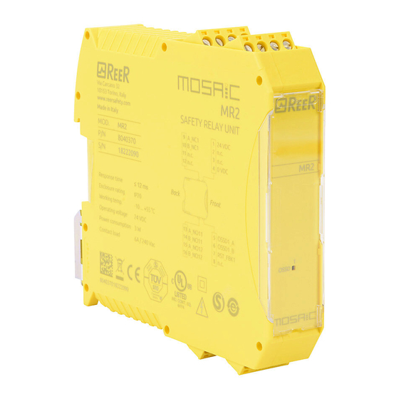
Safety relay modules.
Brand:
Reer
| Category:
Safety Equipment
| Size: 0.33 MB
Advertisement
Related Products
Reer MOSAIC MR4
Reer MOSAIC MO4
Reer MOSAIC MV0
Reer MOSAIC MV1
Reer Mosaic MCT2
Reer Mosaic MOR4
Reer Mosaic MOS16
Reer MOSAIC MBMR
Reer MOSAIC MV2H
Reer MOSAIC MV2T
Reer Categories
Baby Monitor
Safety Equipment
Security Sensors
Thermometer
Controller
More Reer Manuals
Login
Sign In
OR
Sign in with Facebook
Sign in with Google
Upload manual
Upload from disk
Upload from URL